Table of Contents
Advertisement
Quick Links
Advertisement
Table of Contents
Troubleshooting

Related Manuals for Amsco Evolution Series


Summary of Contents for Amsco Evolution Series
- Page 1 OPERATOR MANUAL ® ® AMSCO Evolution Series Steam Sterilizers Rev AD 129390199...
- Page 3 Indications for Use The AMSCO Evolution Series Steam Sterilizer is designed for sterilization of heat- and moisture-stable materials used in healthcare facilities. Prevacuum – designed for sterilization of heat- and moisture-stable materials.
- Page 4 Table 1. Factory-Set Cycles and Cycle Values for Evolution Prevacuum Sterilizer Sterilize Validation Cycles Sterilize Temp. Time Dry Time Recommended Load Standard 1. PREVAC 270°F (132°C) 4 Min. 30 Min. Double-wrapped instrument trays, ST-8 max. weight of 25 lbs (11.3 kg) each. Fabric Packs.
- Page 5 Table 2. Factory-Set Cycles and Cycle Values for Evolution SFPP Sterilizer Sterilize Validation Cycles Sterilize Temp. Time Time Recommended Load Standard 1. SFPP 270°F (132°C) 4 Min. 30 Min.* Double-wrapped instrument trays, ST-8 max. weight of 25 lbs (11.3 kg) each. Fabric packs.
- Page 6 Table 3. Test Cycles Test Cycles for Sterilize Validation All Units Temp. Sterilize Time Time Recommended Load Standard † 270°F (132°C) 4 Min. 1 Min. DART Warm-up † 270°F (132°C) 3 Min., 30 Sec 1 Min. DART or ST-8 DART Bowie-Dick Test Pack (Bowie-Dick) Test...
- Page 7 Cross reference model number to chamber size and capacity using table below: Table 6. Sterilizer Chamber Volume Model Chamber Size Volume HC-900 26 x 37.5 x 42" (660 x 953 x 1067 mm) 40,950 in / 23.7 ft HC-1200 26 x 37.5 x 54" (660 x 953 x 1372 mm) 52,650 in / 30.5 ft HC-1500...
- Page 8 Table 9. Sterilizer Vertical-Sliding Door Configurations 26 x 26" 26 x 26 x 39" (660 x 660 x 991 mm) Single Door, Prevacuum Double Door, Prevacuum 26 x 26 x 39" (660 x 660 x 991 mm) Single Door, SFPP Double Door, SFPP 26 x 26 x 49"...
- Page 9 Service Information A thorough preventive maintenance program is essential to safe and proper sterilizer operation. Customers are encouraged to contact STERIS concerning our annual maintenance program. Under terms of this program, preventive maintenance, adjustments and replacement of worn parts are provided on a scheduled basis to help assure optimal equipment performance at peak capability and to help minimize untimely or costly interruptions.
- Page 10 viii 129390199 Operator Manual Introduction...
-
Page 11: Table Of Contents
TABLE OF CONTENTS Section Number Description Page Safety Precautions ........................1-1 Symbol Definitions ........................2-1 Installation Verification ......................... 3-1 Installation Checklist ..........................3-1 3.1.1 Service Clearance........................3-1 3.1.2 Plumbing Services ........................3-1 3.1.3 Electrical Service.......................... 3-2 3.1.4 Sterilizer Final Check ........................3-2 3.1.5 Cycle Operation ........................... -
Page 12: Number Description Page
Section Number Description Page Sterilizer Operation ........................6-1 Before Operating the Sterilizer ......................6-1 Preparing Loads for Sterilization Cycles ....................6-6 Guidelines for Placement of Various Loads................... 6-6 Loading Cart and Transfer Carriage Instructions: Loading ..............6-7 Loading Cart and Transfer Carriage: Unloading ..................6-9 Floor Loading Sterilizer Loading and Unloading .................. - Page 13 Section Number Description Page Routine Maintenance........................8-1 Preventive Maintenance ........................8-1 Daily Maintenance ..........................8-2 8.2.1 Replace Printer Paper Roll......................8-2 Weekly Maintenance ..........................8-4 8.3.1 Clean Chamber ..........................8-5 Troubleshooting ..........................9-1 General ..............................9-1 9.1.1 Typical Alarm Screen ........................9-2 9.1.2 Typical Alarm Printout ........................
- Page 14 Section Number Description Page 9.4.10OE/NOE Door Switches Malfunction..................9-21 9.4.11 Exhaust Rate Too Slow......................9-21 9.4.12 Exhaust Rate Too Fast ......................9-22 9.4.13Generator Alarm......................... 9-22 Water Conservation System Alarms ....................9-23 9.5.1 Tank Water Too Hot (Green Machine) ........................9-23 9.5.2 Too Long to Fill Tank (Green Machine) ........................
- Page 15 LIST OF FIGURES Figure Number and Description Page Figure 4-1. Vented Closures........................... 4-5 Figure 5-1. Component Identification (26 x 26” Sterilizer Shown) ................5-1 Figure 5-2. Sterilizer Key Switch ..........................5-3 Figure 5-3. Typical Out-of-Cycle Display ........................ 5-4 Figure 5-4. Typical In-Cycle and In-Cycle Status Display ..................5-4 Figure 5-5.
-
Page 16: Figure Number And Description Page
Figure Number and Description Page Figure 8-4. Take-Up Spool ............................. 8-3 Figure 9-1. Alarm and Alarm Detail Screen Features ..................... 9-2 Figure 9-2. Typical Alarm Printout .......................... 9-3 Figure 10-1. Door Seal Replacement, 26 x 26” (660 x 660 mm) Sterilizers ............10-4 Figure 10-2. - Page 17 LIST OF TABLES Table Number and Description Page Table 1. Factory-Set Cycles and Cycle Values for Evolution Prevacuum Sterilizer..........0-ii Table 2. Factory-Set Cycles and Cycle Values for Evolution SFPP Sterilizer ............0-iii Table 3. Test Cycles .............................. 0-iv Table 4. Recommended Loads by Sterilizer Chamber Size .................. 0-iv Table 5.
- Page 18 129390199 Operator Manual Table of Contents...
-
Page 19: Safety Precautions
SAFETY PRECAUTIONS ® ® The following Safety Precautions must be observed when operating or servicing this AMSCO Evolution Series Steam Sterilizer. WARNING indicates the potential for personal injury and CAUTION indicates the potential for damage to equipment. For emphasis, certain Safety Precautions are repeated throughout the manual. It is important to review all Safety Precautions before operating or servicing the unit. - Page 20 Personnel must properly shutdown the sterilizer and retain the power key at all times while cleaning the sterilizer chamber. Avoid personal injury from bursting bottles. Liquid sterilization cycle must only be used for liquids in borosilicate (Pyrex) flasks with vented closures. WARNING –...
- Page 21 WARNING – SLIPPING HAZARD: To reduce slippery conditions, keep floors dry by immediately wiping up any spilled liquids or condensation in sterilizer loading and unloading areas. CAUTION – POSSIBLE EQUIPMENT DAMAGE HAZARD: Allow thermostatic steam traps to cool down to room temperature before removing cover. Since there is nothing to limit expansion, the bellows may rupture or fatigue if trap is opened while hot.
- Page 22 129390199 Operator Manual Safety Precautions...
-
Page 23: Symbol Definitions
SYMBOL DEFINITIONS The following symbols appear on AMSCO Evolution Series Steam Sterilizers and are provided here for reference. Table 2-1. Symbol Definitions Symbol Definition Symbol Definition Transfer of heat, hot Machine Setup Button surface Protective earth (i.e., Adjust Audible signals... - Page 24 Table 2-1. Symbol Definitions (Continued) Symbol Definition Symbol Definition Spanish-language Alternating current selection button French-language Amperage rating of unit selection button Set Utilities Control Frequency rating of unit Button Ø Phase of the unit Lockout Button Standby Button Set Print Options Button Start Cycle Button Set Machine ID Button Duplicate Print Button...
- Page 25 Table 2-1. Symbol Definitions (Continued) Symbol Definition Symbol Definition Display Abort Status Set Time Button Button Display Chamber Options Button Temperature and Pressure Status Change Cycle Values Alarm Details Button Button Alarm Status Button OK (Accept) Button Backspace Button (erase Advance Screen Button entered characters) Exit Screen Button...
- Page 26 129390199 Operator Manual Symbol Definitions...
-
Page 27: Installation Verification
INSTALLATION VERIFICATION 3.1 Installation An Equipment Drawing showing all utility and space requirements was supplied with the sterilizer. Clearance space shown on the drawing is Checklist necessary for ease of installation and to assure proper operation and maintenance of equipment. Uncrating and Installation Instructions were also furnished with the sterilizer. -
Page 28: Electrical Service
Air Supply: ❑ Supply line shutoff with provisions for lockout and tagout located near the equipment. ❑ Air pressure 80 to 120 psi (5.5 to 8.3 bar), dynamic. ❑ The protective earth ground must be connected to terminal block 3.1.3 Electrical Service TB-1 in the sterilizer power box. -
Page 29: Technical Specifications
3.2 Technical Specifications 3.2.1 Overall Exterior Dimensions W x H x L Table 3-1. Sterilizer Overall Exterior Dimensions Sterilizer Model Exterior Dimensions (W x H x L) HC 600 Sliding Door 52 x 80.5 x 64" (1321 x 2045 x 1626 mm) HC 800 Sliding Door 52 x 80-1/2 x 74"... -
Page 30: Fully Loaded Weight
3.2.2 Fully Loaded Weight Table 3-2. Sterilizer Weights – Fully Loaded Sterilizer Model Sterilizer Weight (Fully Loaded) HC 600 Sliding Door 2756 lbs (1250 kg) HC 800 Sliding Door 3200 lbs (1450 kg) HC 1000 Sliding Door 3500 lbs (1590 kg) HC 900 Sliding Door 3800 lbs (1720 kg) -
Page 31: Utility Requirements
3.2.3 Utility Requirements • Electric: 208/240 V ac, 3-phase, 50/60 Hz, 12 A / phase, 480 V ac, 3-phase, 50/60 Hz, 6 A / phase See Equipment Drawings for electrical requirements for sterilizers with integral electric steam generators. • Steam: Pressure: 50 to 80 psig (3.5 to 5.5 bar) Consumption, Peak: Approximately 455 lbs/hr (206 kg/hr) •... - Page 32 129390199 Operator Manual Installation Verification...
-
Page 33: Techniques Of Sterilization
TECHNIQUES OF STERILIZATION 4.1 General The information in this section is intended as a general guide to steam sterilization techniques. Also recommended is reference to the standards of the ANSI/AAMI ST-79, Comprehensive Guide to Steam Sterilization and Sterility Assurance in Health Care Facilities. •... -
Page 34: Control Measure For Verifying Sterilization Process
4.2 Control Measure As part of the operator’s verification of the sterilization process, for Verifying biological indicators may be used to demonstrate that sterilization conditions have been met. Sterilization Process 4.2.1 Biological Monitors A live spore test utilizing G. stearothermophilus is the most reliable form of biological monitoring. -
Page 35: Vacuum Leak Test
For SFPP sterilizers, if the SFPP cycle is used exclusively, there is no need to run a daily Dart (Bowie-Dick) test. If prevacuum cycles will also be run on the same sterilizer, then a daily Dart (Bowie-Dick) test must be run. NOTE: The Dart (Bowie-Dick) test cycle is not a test for adequate exposure to heat in terms of time-at-temperature. -
Page 36: Techniques Of Sterilization For Liquid Cycle
4.4 Techniques of Important: It is inappropriate for a healthcare facility to sterilize liquids for direct patient contact. Sterilization for Liquid Cycle Refer to Table 4-1 for recommended Liquid cycle parameters. The recommended times indicated in Table 4-1 assume the use of WARNING –... -
Page 37: Recommendations For Sterilizing Liquids
4.5 Recommendations Important: Please read the following paragraphs before sterilizing any liquids in your sterilizer. It is inappropriate for a healthcare facility for Sterilizing Liquids to sterilize liquids for direct patient contact. WARNING – EXPLOSION Borosilicate glass is required because it is a superior glass capable HAZARD: This sterilizer is not of resisting thermal shock. - Page 38 129390199 Operator Manual Techniques of Sterilization...
-
Page 39: Component Identification
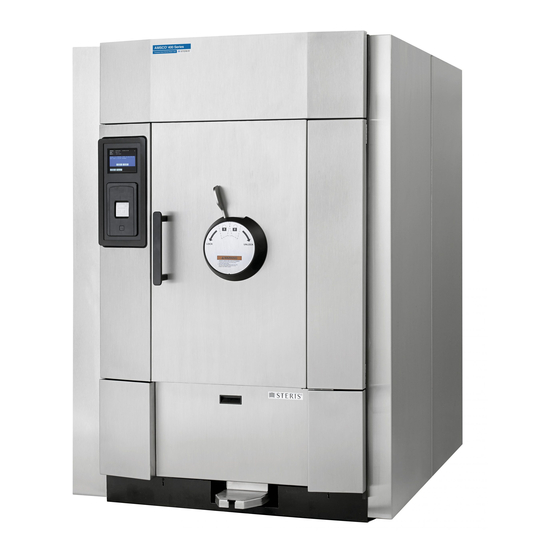
COMPONENT IDENTIFICATION 26 x 26” (660 x 660 mm) Sterilizers Only 26 x 37.5” (660 x 953 mm) Sterilizers Only Control Touch Screen Chamber Pressure Gauge Jacket Pressure Gauge Open (Lower/Move Left) Door Button (Power Door Only) Close (Raise/Move Right) Door Button (Power Door Only) Printer Emergency Stop Button... -
Page 40: General
5.1 General Use this manual to become familiar with control locations and functions before operating the sterilizer (refer to Figures 5-1 through 5-14). The controls for this sterilizer are contained within the control touch screen. Control touch pads appear on the screen as needed during each operation. -
Page 41: Sterilizer Key Switch Operation
5.3 Sterilizer Key Switch Operation Key Switch Function: The key switch has two positions – 0 (Off) and I (On). When power is supplied to sterilizer, the key should be in the 0 (Off) position. When the key is moved to I (On) position, 24V dc power is applied to control and power-up sequence begins. -
Page 42: Control
5.4 Control Control displays can be divided into two categories, those occurring when the sterilizer is “out-of-cycle” and those occurring when the sterilizer is “in-cycle.” Typical out-of-cycle and in-cycle displays are shown in Figures 5-3 and 5-4. • Out-of-cycle displays are used to start cycles, or set up and adjust sterilizer operation. -
Page 43: Alarm Displays
5.5 Alarm Displays Alarm displays tell operators and technicians when the sterilizer is experiencing an abnormal condition. Alarm conditions can be caused by failure of utility supplies or sterilizer components. 9, T , details the steps an operator can take ECTION ROUBLESHOOTING to solve most alarm conditions. -
Page 44: Cycle Selection Touch Pads
Cycle status and control messages are shown on an 8-2/5 inch (213 mm) color graphics display. Cycles can be started or aborted using the touch screen pads. Cycles and cycle values can be set using the Change Values procedure (accessible from the sterilizer cycle select screen). -
Page 45: Change Values Control Screens
® ® The AMSCO Evolution Series Steam Sterilizer control can be programmed to retain values for up to 12 separate cycles. The eight cycles shown on two cycle select screens, are the factory default cycles. Up to four additional cycles can be programmed and displayed on a third cycle select screen. -
Page 46: Abort Touch-Screen Button
5.7.2 Abort Touch-Screen The Abort button is used to end a cycle before it completes normally. Button A cycle only needs to be aborted if an abnormal condition or a control problem develops during the cycle. Pressing Abort causes the sterilizer chamber to depressurize (if pressurized), or air break (if in vacuum);... -
Page 47: Printer
5.8 Printer Printer records all cycle data on 2.25” (57 mm) wide single-ply paper. See S 8.2.1. R 8-2 for ECTION EPLACE RINTER APER PAGE paper changing procedure. Paper Feed Paper Cut Figure 5-12. Thermal Printer • Paper Feed – Located on the upper front of printer door, just left of center. -
Page 48: Printouts
5.9 Printouts Refer to Figure 5-14. The printout reports useful information about each cycle the sterilizer runs; including the load number, which is a unique identifying code. Each load number is printed in the following format: a two-digit month (e.g., April = 04), a two-digit day (e.g., twenty eighth day = 28) and a two-digit daily cycle count (e.g., first cycle = 01, second = 02, etc.). -
Page 49: Vertical-Sliding Door Operation (26 X 26" Sterilizers)
5.10 Vertical-Sliding The sterilizer door is operated using push buttons near the sterilizer control screen. Refer to Figure 5-1. Door Operation (26 x 26” Sterilizers) • Pressing the “OPEN DOOR” push button while the door is in the closed (up) position causes the door to open (by lowering). •... -
Page 50: Hinged-Door Operation
5.12 Hinged-Door 1. Unlock door by moving door lock control toward the right (refer to Figure 5-15). Operation 2. Grasp door handle and swing door open. Move Lever Move Lever Left to Lock Right to Unlock Door Handle: Pull to open Figure 5-15. -
Page 51: Sterilizer Operation
STERILIZER OPERATION 6.1 Before Operating Operate sterilizer by referring to the cycle description in ECTION 6.9, P 6-15. the Sterilizer REVAC YCLES PAGE 1. Press anywhere on the touch-screen of the sterilizer control WARNING – BURN HAZARD: display. Sterilizer, rack/shelves, and 2. -
Page 52: Table 6-1. Factory-Set Cycles And Cycle Values For Evolution Prevacuum Sterilizer
Table 6-1. Factory-Set Cycles and Cycle Values for Evolution Prevacuum Sterilizer Sterilize Validation ‡ Cycles Sterilize Temp. Time Time Recommended Load Standard 1. PREVAC 270°F (132°C) 4 Min. 30 Min. Double-wrapped instrument trays, ST-8 max. weight of 25 lbs (11.3 kg) each. Fabric Packs. -
Page 53: Table 6-2. Factory-Set Cycles And Cycle Values For Evolution Sfpp Sterilizer
Table 6-2. Factory-Set Cycles and Cycle Values for Evolution SFPP Sterilizer Sterilize Validation ‡ Cycles Sterilize Temp. Time Time Recommended Load Standard 1. SFPP 270°F (132°C) 4 Min. 30 Min.* Double-wrapped instrument trays, ST-8 max. weight of 25 lbs (11.3 kg) each. Fabric packs. -
Page 54: Table 6-3. Test Cycles
Table 6-3. Test Cycles Test Cycles for Sterilize Validation All Units Temp. Sterilize Time Time Recommended Load Standard 270°F (132°C) 4 Min. 1 Min. DART Warm-up DART (Bowie- 270°F (132°C) 3 Min., 30 Sec 1 Min. DART or Bowie-Dick Test ST-8 Pack Dick) Test... -
Page 55: Table 6-6. Sterilizer Chamber Volume
Cross reference model number to chamber size and capacity using table below: Table 6-6. Sterilizer Chamber Volume Model Chamber Size Volume HC-900 26 x 37.5 x 42" (660 x 953 x 1067 mm) 40,950 in / 23.7 ft HC-1200 26 x 37.5 x 54" (660 x 953 x 1372 mm) 52,650 in / 30.5 ft HC-1500... -
Page 56: Preparing Loads For Sterilization Cycles
6.2 Preparing Loads Before sterilization, all materials must be thoroughly cleaned. for Sterilization Cycles ® ® The AMSCO Evolution Series Steam Sterilizer chamber holds wrapped or unwrapped instruments and equipment. 1. Wrappers may be made of 100% cotton (muslin), 140 thread count, two-ply fabric, and must be laundered;... -
Page 57: Loading Cart And Transfer Carriage Instructions: Loading
6.4 Loading Cart and 1. Open sterilizer door. Transfer Carriage 2. Verify loading cart is properly aligned upon transfer carriage. Instructions: Loading 3. Align front end of transfer carriage with dock at base of sterilizer. (See Figure 6-1 Figure 6-2.) 4. -
Page 58: Figure 6-2. Loading Goods Into Sterilizer Chamber
Loading Cart Transfer Carriage Carriage Docking Interface Hand Crank Figure 6-2. Loading Goods into Sterilizer Chamber 129390199 Operator Manual Sterilizer Operation... -
Page 59: Loading Cart And Transfer Carriage: Unloading
6.5 Loading Cart and Refer to Figure 6-2. Transfer Carriage: Unloading 1. Open chamber door. WARNING – BURN HAZARD: 2. Move transfer carriage forward until it engages with dock. • Sterilizer, rack/shelves and 3. Once transfer carriage engages with dock, transfer carriage loading equipment will be latches to dock as it begins pushing into chamber. -
Page 60: Floor Loading Sterilizer Loading And Unloading
6.6 Floor Loading Refer to Figure 6-3. Sterilizer • 26 x 61 x 49 (660 x 1550 x 1245 mm) accommodates one 48- Loading and Unloading inch (1219 mm) loading cart. • 26 x 61 x 72 (660 x 1550 x 1850 mm) accommodates one 28- inch (711 mm) loading cart and one 42-inch (1067 mm) loading cart. -
Page 61: Unloading The Sterilizer
Loading Car Figure 6-3. Loading Floorloader Sterilizer Chamber 6.7 Unloading the The control informs the user when a cycle is complete and prompts the user to open door and unload sterilizer. Open the chamber door Sterilizer at the end of a cycle, when end-of-cycle tone sounds and the screen display is as follows: 6-11 Sterilizer Operation... -
Page 62: Figure 6-4. Cycles Screen -Door Interlock Feature Enabled
NOTE: Wear clean gloves and use clean towels to insulate the WARNING – BURN HAZARD: operator’s hand from heat when carefully removing load/tray(s) from • Sterilizer, rack/shelves and loading cart. loading cart will be hot after NOTE: Never place a sterilized tray on a solid shelf or cold surface. cycle is run. -
Page 63: Prevacuum Sterilizer Cycle
6.8 Prevacuum AMSCO Evolution Series Steam Sterilizers are shipped with factory- set cycle values. The cycle sequence for these cycles are given in Sterilizer Cycle 6.9, P , on 6-15. Refer to Table 6-8 for ECTION REVAC YCLES PAGE factory set, qualified cycle settings. -
Page 64: Table 6-8. Factory-Set Prevacuum Cycles And Cycle Values
Table 6-8. Factory-Set Prevacuum Cycles and Cycle Values The AMSCO Evolution Series Prevacuum Sterilizer is equipped with the following factory programmed prevacuum sterilization cycles and cycle values. Sterilize Validation Cycles Sterilize Temp. Time* Time Recommended Load Standard PREVAC 270°F (132°C) 4 Min. -
Page 65: Prevac Cycles
6.9 Prevac Cycles Prevac cycles, 270°F (132°C), are used for sterilizing double- wrapped instrument trays or fabric packs. Prevac cycles, 275°F (135°C), are used for sterilizing double-wrapped instrument trays only. 1. Before running this cycle refer to S 6.1, B ECTION EFORE PERATING... - Page 66 DRY – Start of dry is printed and display counts down dry time remaining. AIR BREAK – Chamber is returned to atmospheric pressure. RETRACT SEAL – A vacuum is drawn on the seal, retracting it from inner surface of door. COMPLETE –...
- Page 67 270°F (132°C) Prevacuum 275°F (135°C) Prevacuum Cycle Printout Cycle Printout Figure 6-6. Prevacuum Cycle Printouts (270°F [132°C] and 275°F [135°C]) 6-17 Sterilizer Operation Operator Manual 129390199...
-
Page 68: Table 6-9. Factory-Set Gravity Cycles And Cycle Values
Table 6-9. Factory-Set Gravity Cycles and Cycle Values The AMSCO Evolution Series Prevacuum Sterilizer is equipped with the following factory programmed gravity sterilization cycles and cycle values. Sterilize Validation † Cycles Sterilize Temp. Time Time Recommended Load Standard GRAVITY 250°F (121°C) 30 Min. -
Page 69: Gravity Cycles
6.10 Gravity Cycles The Gravity cycle is used for sterilizing double-wrapped instrument trays and fabric packs. WARNING – BURN HAZARD: 1. Refer to S 6.1, B , on ECTION EFORE PERATING THE TERILIZER PAGE 6-1 before running this cycle. • Sterilizer, rack/shelves, and loading equipment will be hot 2. -
Page 70: Figure 6-8. Typical Gravity Cycle Printouts
250°F (121°C) Gravity Cycle Printout 270°F (132°C) Gravity Cycle Printout Figure 6-8. Typical Gravity Cycle Printouts 6-20 129390199 Operator Manual Sterilizer Operation... - Page 71 6-21 Sterilizer Operation Operator Manual 129390199...
-
Page 72: Table 6-10. Factory-Set Liquid Cycle And Cycle Values
Table 6-10. Factory-Set Liquid Cycle and Cycle Values The AMSCO Evolution Series Prevacuum Sterilizer is equipped with the following factory programmed liquid sterilization cycle and cycle values. Sterilize Validation † Cycles Sterilize Temp. Time Time Recommended Load Standard 250°F (121°C) 45 Min. -
Page 73: Liquid Cycle
6.11 Liquid Cycle This cycle is used for sterilizing liquids in vented closures. 1. Refer to S 6.1, B , on ECTION EFORE PERATING THE TERILIZER PAGE WARNING – EXPLOSION 6-1 before running this cycle. HAZARD: This sterilizer is not 2. -
Page 74: Figure 6-10. Typical Printout Of A Liquid Cycle
Figure 6-10. Typical Printout of a Liquid Cycle 6-24 129390199 Operator Manual Sterilizer Operation... -
Page 75: Sfpp Sterilizer Cycles
6.12 SFPP Sterilizer AMSCO Evolution Series SFPP Steam Sterilizers are shipped with factory-set cycles. The cycle sequence for these cycles is given in Cycles 6.12, SFPP S , on 6-25. Refer below, ECTION TERILIZER YCLES PAGE and to Table 6-2 and Table 6-3 for factory-set, qualified cycle settings. -
Page 76: Table 6-11. Factory-Set Cycles And Cycle Values Sfpp Sterilizer
Table 6-11. Factory-Set Cycles and Cycle Values SFPP Sterilizer Sterilize Validation † Cycles Sterilize Temp. Time Time Recommended Load Standard SFPP 270°F (132°C) 4 Min. Double-wrapped instrument ST-8 30 Min. trays, max. weight of 25 lbs (11.3 kg) each. Fabric packs. -
Page 77: Sfpp Cycles
6.13 SFPP Cycles SFPP cycles are designed for sterilizing both fabric packs and instrument trays. The cycle conditions loads at above-atmospheric pressure. SFPP cycles feature three steam flush pressure pulses, a WARNING – BURN HAZARD: sterilization time of 4 minutes at 270°F and a 30-minute dry time. •... -
Page 78: Figure 6-12. Typical Printouts - Sfpp Cycles (270°And 275°F)
Figure 6-12. Typical Printouts — SFPP Cycles (270°and 275°F) 6-28 129390199 Operator Manual Sterilizer Operation... - Page 79 6-29 Sterilizer Operation Operator Manual 129390199...
-
Page 80: Test Cycles
6.14 Test Cycles Test cycles are factory programmed on prevacuum sterilizers. These cycles are used to verify the sterilizer is functioning at optimum capability. Table 6-12. Test Cycles Test Cycles for Sterilize Validation All Units Temp. Sterilize Time Time Recommended Load Standard 270°F (132°C) 4 Min. -
Page 81: Dart (Bowie-Dick) Test
6.14.1 Dart (Bowie-Dick) Test This cycle is used to conduct a Dart (Bowie-Dick) test on sterilizers that use prevacuum cycles. This test is only applicable to sterilizers that use prevacuum cycles. For SFPP sterilizers, if the SFPP cycle is used exclusively, there is no need to run a daily Dart (Bowie-Dick) test. - Page 82 printed every minute. Chamber is controlled at set point plus overdrive. FAST EXHAUST – Start of exhaust is printed and chamber is WARNING – BURN HAZARD: exhausted to 4 psig (0.28 bar). • Sterilizer, rack/shelves and DRY – Start of dry is printed and display counts down dry time loading equipment will be hot remaining.
-
Page 83: Figure 6-14. Dart (Bowie-Dick) Test Cycle Printout
Figure 6-14. Dart (Bowie-Dick) Test Cycle Printout 6-33 Sterilizer Operation Operator Manual 129390199... -
Page 84: Vacuum Leak Test
6.14.2 Vacuum This cycle is used for testing vacuum integrity of sterilizer and piping. Leak Test A Vacuum Leak Test cycle should be run on the sterilizer at least WARNING – BURN HAZARD: once each week. It should be one of the first cycles run for the day. •... -
Page 85: Figure 6-15. Vacuum Leak Test Cycle Printout
Figure 6-15. Vacuum Leak Test Cycle Printout 6-35 Sterilizer Operation Operator Manual 129390199... -
Page 86: Aborting Cycles
6.15 Aborting Cycles It may be necessary to end a processing cycle, possibly because the wrong cycle was selected or the sterilizer begins functioning incorrectly. A cycle can be aborted at any time by pressing the Abort touch-screen button. 1. Touch the Abort button. WARNING –... - Page 87 Press the silence alarm button to turn off the alarm speaker during the abort sequence. Press the status touch pad in the lower left hand corner of the screen at any time to display an abort- status screen (typical sample below): 3.
-
Page 88: Emergency Manual Exhaust
6.16 Emergency Important: Air pressure to the air manifold is required for this Manual Exhaust procedure. Air manifold is located on top rail of plumbing stand (in service area). If a power failure should occur in the facility, or the sterilizer should WARNING –... -
Page 89: Cycle Graphs
Once vapor and heat have escaped chamber, push door fully open and remove load. 6.17 Cycle Graphs Cycle graphs for the AMSCO Evolution Series Steam Sterilizers are shown in Figures 6-17, 6-18, 6-19, 6-20 and 6-21. 6-39 Sterilizer Operation... -
Page 90: Figure 6-17. Cycle Graph: Prevacuum And Bowie-Dick (Dart) Cycles
Figure 6-17. Cycle Graph: Prevacuum and Bowie-Dick (Dart) Cycles 6-40 129390199 Operator Manual Sterilizer Operation... -
Page 91: Figure 6-18. Cycle Graph: Gravity Cycle
Figure 6-18. Cycle Graph: Gravity Cycle 6-41 Sterilizer Operation Operator Manual 129390199... -
Page 92: Figure 6-19. Cycle Graph: Liquid Cycle
Figure 6-19. Cycle Graph: Liquid Cycle 6-42 129390199 Operator Manual Sterilizer Operation... -
Page 93: Figure 6-20. Cycle Graph: Steam Flush Pressure Pulse (Sfpp) Cycle
Figure 6-20. Cycle Graph: Steam Flush Pressure Pulse (SFPP) Cycle 6-43 Sterilizer Operation Operator Manual 129390199... -
Page 94: Figure 6-21. Cycle Graph: Leak Test Cycle
Figure 6-21. Cycle Graph: Leak Test Cycle 6-44 129390199 Operator Manual Sterilizer Operation... -
Page 95: Cycle And Control Value Programming
CYCLE AND CONTROL VALUE PROGRAMMING ® AMSCO Evolution Series Steam Sterilizers are shipped with ® factory-set cycles, cycle values and control values programmed into the control (see Table 7-1). These preset values can be changed to tailor the sterilizer to the operating environment in which it has been installed. -
Page 96: Cycle Values
7.1 Cycle Values AMSCO Evolution sterilizers are shipped with the default cycle values shown in Table 7-1. The Prevacuum Configuration AMSCO Evolution Sterilizer is equipped with the following factory programmed sterilization cycle values (Table 7-1). Table 7-1. Factory-Set Cycles and Cycle Values for Evolution Prevacuum Sterilizer... -
Page 97: Table 7-2. Factory-Set Cycles And Cycle Values For Evolution Sfpp Sterilizer
Table 7-2. Factory-Set Cycles and Cycle Values for Evolution SFPP Sterilizer Sterilize Validation Cycles Sterilize Temp. Time Time Recommended Load Standard 1. SFPP 270°F (132°C) 4 Min. Double-wrapped instrument trays, ST-8 30 Min. max. weight of 25 lbs (11.3 kg) each. Fabric packs. -
Page 98: Change Values
7.2 Change Values Important: Applicable cycles have been validated to satisfy the requirements outlined in Table 1 (page ii) and Table 2 (page iii). If cycle parameters (sterilize time or dry time) other than those in Table 7-1 are required, it is the responsibility of the healthcare facility to consult and follow the device manufacturer’s written instructions. -
Page 99: Table 7-3. Adjustment Ranges For Cycle Values
7.3 Change Cycle Important: Applicable cycles have been validated to satisfy the requirements outlined in Table 7-1. If cycle parameters (sterilize time Values or dry time) other than those in Table 7-1 are required, it is the responsibility of the healthcare facility to consult and follow the device manufacturer’s written instructions. -
Page 100: Change Cycle Values
7.3.2 Change Cycle Values Procedure Touch Anywhere On Press anywhere on “In Standby” “In Standby” screen to access sterilizer control Screen To Start functions. Press Options Button Press Options button to access “Options” screen (used to adjust sterilizer operation). Press Change Cycle Values Press Change Cycle Values button to Button... - Page 101 Continued from Previous Page Press (backspace) to clear values that have been entered. Press (OK) to accept values that have been entered, and return to change cycle values screen. Press (exit) to abandon any values entered and return to change cycle values screen.
-
Page 102: Change Time And Date
7.4 Change Time and These screens adjust the time and date the sterilizer uses for all display and printout messages. Date The current time and date appears on the Standby and Cycle Status screens. Time and date are also shown on printouts. These should be verified periodically. -
Page 103: Set Time
1. To access this utility, press Options touch pad from the Cycles screen at the operating end of the sterilizer. The screen changes to show the Options screen. Touch Set Date and Time button, the display advances to Change Time/Date screen. 2. - Page 104 a. If an incorrect number is entered, press the backspace key to clear the entry, then use the keypad to enter the correct value. b. Once the correct time has been entered, press OK to accept change hours screen. c. Press EXIT to return to Change Time/Date screen. 4.
- Page 105 b. Once the correct minutes value has been entered, press OK to accept. c. Press EXIT to return to Change Time/Date screen. 5. Change Seconds – use the touch screen key pad to enter the seconds value, this can be between 00 and 59. a.
-
Page 106: Date Format
7.4.3 Date Format This setup option allows the operator to select the “format” for the date. The format determines the order in which the month, day and year are displayed. There are three options, and the option selected is a matter of either preference or geographical location. 1. -
Page 107: Set Date
7.4.4 Set Date At Change Time/Date screen, press Set Date and screen shown below appears. Enter the day value using the keypad. The day value must be between 1 and 31. 1. If an incorrect number is entered, press the backspace key to clear the entry, then use the keypad to enter the correct value. - Page 108 Enter the correct month value using the keypad. The month value must be between 1 and 12. 4. If an incorrect value is entered, press the backspace key to clear the entry, then use the keypad to enter the correct value. 5.
-
Page 109: Change Machine Setup
7. If an incorrect value is entered, press the backspace key to clear the entry, then use the keypad to enter the correct value. 8. Once the correct year value has been entered, press OK to accept. NOTE: The day of the week is automatically understood and registered by the control. -
Page 110: Change Password
7.5.1 Change Password The Change Password screen is used to set the supervisor password. A supervisor password is required for access to Set Time and Date, Machine Setup and Change values screens. Change Password screen is accessed by pressing the Machine Setup button from the Options screen and then pressing the Change Password button. -
Page 111: Future Use
Once a Supervisor password has been set, the Supervisor Access screen (below) displays whenever one of the following buttons is pressed: • Set Date and Time • Change Cycle Values • Machine Setup Entering the 4 digit access code and pressing OK enables access to the specific Options screen. -
Page 112: Utility Control
7.5.3 Utility Control The Utility Control screen is used to automatically control utility services to the sterilizer. As shipped from the factory, this is set to Manual Utilities control (i.e., utilities must be shut off and turned on by an operator). If the sterilizer is equipped with an integral electric steam generator, refer to S 7.5.5, U ECTION... - Page 113 The setting on this screen is either Manual or Automatic. If the utility control button displays Manual (and Automatic operation is preferred), press the utility control button to change setting to Automatic. If Automatic is displayed on the button (and Manual operation is preferred), press the button to change to Manual.
- Page 114 Using automatic utility control, the sterilizer can be set to control the following: • Daily Restart time • Daily Shutoff time NOTE: Restart and Shutoff times are set up separately for each day of the week. 1. Press the Day Of The Week button to select the day to set up for utility control.
- Page 115 4. If an incorrect value is entered, press the backspace key to clear the entry, then use the keypad to enter the correct value. 5. Press Exit to abandon changes and return to the Machine Setup screen. Press OK to save utilities set up changes and return to Utility Control screen.
- Page 116 8. If an incorrect value is entered, press the backspace key to clear the entry, then use the keypad to enter the correct value. 9. Press Exit to abandon changes and return to the Machine Setup screen. Press OK to save utilities set up changes and return to Utility Control screen.
-
Page 117: Utility Control Summary
7.5.4 Utility Control Summary The utility control function allows the operator to display a summary of all the utility controls settings. 1. To display a summary of the automatic utility control restart and Shutoff times that have been entered, press the information key in the upper left-hand corner of the Utility Control screen. -
Page 118: Utility Control With Integral Electric Steam Generator
7.5.5 Utility Control with If the sterilizer is set up to be equipped with an integral electric Integral Electric Steam steam generator, the following screen appears on the display when Utility Control is accessed. This screen adds the option for setting a Generator daily generator flush. -
Page 119: Language
7.5.6 Language The AMSCO Evolution sterilizer is capable of operation with display screens and printouts in three languages. The factory default is English. 1. To access this utility, press the options button from the Cycles screen at the operating end of the sterilizer. The screen changes to show the Machine Setup screen. - Page 120 3. Select the appropriate language by pressing one of the buttons in the middle of the display. The buttons and corresponding languages are listed below. English Language Spanish Language French Language 4. Once the appropriate language is selected press Exit to return to the Change Machine Setup screen.
-
Page 121: Machine Number
7.5.7 Machine Number This is used to enter an identifying, two-character code into the sterilizer control. This code can be any two-digit number between 00 and 99. The Machine Number code is printed out in the header for each cycle printout, allowing for processed goods to be traced back to a specific sterilizer when needed. - Page 122 3. At machine number screen, enter a two-digit code for the sterilizer using the entry keypad. Ensure, however, that each machine number used is different from any others that have been assigned in the facility. 4. If an incorrect value is entered, press the backspace key to clear the entry, then use the keypad to enter the correct value.
-
Page 123: Print Options
7.5.8 Print Options This setup option allows the operator to select the cycle printout “format.” The format determines the type of printout the sterilizer provides during processing. Two options are available. The default Full format provides status prints at each transition point in the cycle, plus additional status at interval points during each phase of the cycle. - Page 124 1. Select the appropriate print format by pressing one of the three buttons on display. • Print Format – Use this option to set the type of print format provided by the sterilizer during cycle operation: • Full – This is the standard format providing a status print for each phase of the cycle and status prints at a predetermined print interval.
-
Page 125: Audible Signals
7.5.9 Audible Signals This setup option allows the operator to adjust selected audible signals heard at the sterilizer control. Three signals can be adjusted. Touch pad and end of cycle signals can be adjusted to one of three volume levels or turned off. Only the volume level of the Alarm signal can be adjusted. - Page 126 3. Select the signal you wish to adjust by pressing the appropriate touch-screen pad in the upper half of the screen. Press each button multiple times to cycle through the available volume levels (including Off, when applicable) for the selected signal type: NOTE: End of Cycle provides an OFF setting.
-
Page 127: Units
This function allows selection of either Fahrenheit or Celsius units for displaying and printing temperature. Pressure units can be changed between psig/inHg or bar. NOTE: Although Amsco Evolution Series Steam Sterilizers are factory-set to operate using Fahrenheit temperature units, the sterilizer can be reprogrammed to display and print using Celsius temperature units. -
Page 128: Leaving Machine Setup
3. At Units screen, press the appropriate button for the type of unit or units to be selected. • Press Temp Units button to toggle between Fahrenheit (°F) and Celsius (°C). • Press Pressure Units button to toggle between PSIG and bar. -
Page 129: Routine Maintenance
ROUTINE MAINTENANCE 8.1 Preventive Maintenance WARNING – SHOCK AND BURN HAZARD: Regularly scheduled preventive maintenance is required for safe and reliable operation of this equipment. Contact your STERIS Service Representative to schedule preventive maintenance. Observe all preventive maintenance procedures in the following pages to properly maintain this equipment. -
Page 130: Daily Maintenance
8.2 Daily Maintenance Clean Chamber Drain Strainer Important: The chamber drain strainer must be cleaned at least once a day, preferably in the morning before running the first cycle. 1. Remove the drain strainer from the drain in the bottom of the WARNING –... -
Page 131: Figure 8-3. Positioning Paper Roll
2. Lift Inner Cover as shown in Figure 8-3. 3. Position paper roll as follows: a. Position paper roll in bottom of printer compartment, paper coming from bottom of roll. b. Ensure at least 8” (203 mm) of paper extends from printer compartment. -
Page 132: Weekly Maintenance
8.3 Weekly Flush Chamber Drain Maintenance Flush chamber drain as follows once a week: 1. Turn off steam supply valve. • Wait until jacket pressure is zero. • Wait until chamber has cooled to room temperature. 2. Remove chamber drain strainer. Clean strainer using WARNING –... -
Page 133: Clean Chamber
8.3.1 Clean Chamber Important: Professional cleaning of the chamber on a yearly basis (or as required due to local conditions) is suggested to maintain appearance of the chamber interior. Contact STERIS for information regarding this service. • Chamber must be at room temperature, sterilizer off all night, WARNING –... - Page 134 129390199 Operator Manual Routine Maintenance...
-
Page 135: Troubleshooting
TROUBLESHOOTING 9.1 General This section pictorially lists and describes alarm conditions that may ® ® occur when operating the AMSCO Evolution Series Steam Sterilizer. NOTE: Never permit unqualified persons to service the sterilizer. WARNING – PERSONAL Important: The Service Information provided in the following pages... -
Page 136: Typical Alarm Screen
9.1.1 Typical Alarm Screen When an alarm condition occurs, the alarm tone sounds and the touch screen automatically displays the corresponding alarm screen. Typically, each alarm screen indicates the alarm name, the time of day and the date. The alarm details screen (if available), provides more information, including operator instructions. -
Page 137: Typical Alarm Printout
9.1.2 Typical Alarm Printout When an alarm occurs the printer automatically generates a printout, typically listing alarm name, time alarm occurred, current chamber status and any associated sensor temperature. See Figure 9-2. * Alarm XX/XX/XX PRESSURE IN CHAMBER F XX:XX:XXA/P X:XX A/P Full Print Format Shown Figure 9-2. - Page 138 Table 9-1. Operator Troubleshooting – In-Cycle Alarms (Continued) Condition Alarm Screen on Sterilizer Control Service Information 9.2.2 Too Long In Alarm Screen Chamber did not exhaust to atmospheric pressure within Exhaust allotted time. Occurs if chamber does not Causes and Correction: exhaust to 4 psig (0.28 bar) 1.
-
Page 139: Too Long In Evacuation
Table 9-1. Operator Troubleshooting – In-Cycle Alarms (Continued) Condition Alarm Screen on Sterilizer Control Service Information 9.2.3 Too Long In Alarm Screen Chamber reach Evacuation required vacuum level within allotted time. Occurs if chamber does not Causes and Correction: reach the set evacuation 1. -
Page 140: Too Long In Air Break
Table 9-1. Operator Troubleshooting – In-Cycle Alarms (Continued) Condition Alarm Screen on Sterilizer Control Service Information 9.2.4 Too Long In Alarm Screen Chamber did not air break vacuum to 2 inHg (0.1 vbar) Air Break within allotted time Occurs if chamber does not Causes and Correction: air break the vacuum to 2 1. -
Page 141: Over Sterilize Temperature
Table 9-1. Operator Troubleshooting – In-Cycle Alarms (Continued) Condition Alarm Screen on Sterilizer Control Service Information 9.2.6 Over Sterilize Alarm Screen Sterilize temperature is above setpoint more than Temperature prescribed amount. Occurs if chamber Causes And Correction: temperature exceeds the 1. -
Page 142: Oe/Noe Door Unsealed
Table 9-1. Operator Troubleshooting – In-Cycle Alarms (Continued) Condition Alarm Screen on Sterilizer Control Service Information 9.2.7 OE/NOE Door Alarm Screen Steam pressure in OE or NOE door seal below 5 psig Unsealed (0.4 bar) Occurs if steam pressure in Causes And Correction: operating end (OE) or non- 1. -
Page 143: Chamber Pressure/Temperature Failure
Table 9-1. Operator Troubleshooting – In-Cycle Alarms (Continued) Condition Alarm Screen on Sterilizer Control Service Information 9.2.8 Chamber Alarm Screen Pressure temperature outside normal steam range. Pressure/ Temperature Failure Causes and Correction: 1. Control out of calibration Occurs if chamber pressure •... - Page 144 Table 9-1. Operator Troubleshooting – In-Cycle Alarms (Continued) Condition Alarm Screen on Sterilizer Control Service Information 9.2.10 Steam Utility Alarm Screen Check steam utility supply and restore to proper Failure operation. Steam supply to sterilizer is Causes and Corrections: shut off or has failed. 1.
- Page 145 Table 9-1. Operator Troubleshooting – In-Cycle Alarms (Continued) Condition Alarm Screen on Sterilizer Control Service Information 9.2.11 Water Utility Alarm Screen Check water utility supply and restore to proper operation. Failure Causes and Corrections: Water supply to sterilizer is 1. Water pressure less than shut off or has failed.
-
Page 146: Out-Of-Cycle Alarms
9.3 Out-of-cycle The following alarm screens will appear only when the sterilizer is not processing a cycle. Alarms Table 9-2. Operator Troubleshooting – Out-of-Cycle Alarms Condition Alarm Screen on Sterilizer Control Service Information 9.3.1 Too Long To Alarm Screen Door switch did not make contact in allotted time. -
Page 147: Too Long To Open Oe (Or Noe) Door
Table 9-2. Operator Troubleshooting – Out-of-Cycle Alarms (Continued) Condition Alarm Screen on Sterilizer Control Service Information 9.3.2 Too Long To Alarm Screen Door switch did not open in allotted time. Open OE (or NOE) Door Causes and Correction: 1. Door switch malfunction Occurs if door switch does •... -
Page 148: Waste Temperature Probe Failure
Table 9-2. Operator Troubleshooting – Out-of-Cycle Alarms (Continued) Condition Alarm Screen on Sterilizer Control Service Information 9.3.4 Waste Alarm Screen RTD probe, RTD4, output is outside normal range. Temperature Probe Failure Causes and Correction: 1. Loose connections in probe Occurs if waste line wiring temperature reading is •... -
Page 149: Emergency Stop Button Pressed
Table 9-2. Operator Troubleshooting – Out-of-Cycle Alarms (Continued) Condition Alarm Screen on Sterilizer Control Service Information 9.3.6 Emergency Alarm Screen The emergency stop button was pressed either in or out of cycle. Stop Button Pressed Causes and Correction: 1. Correct the emergency The emergency stop condition (if any) that button has been pressed,... -
Page 150: Sensor Alarms
9.4 Sensor Alarms The following alarm screens appear anytime the sterilizer is energized. The sensors are continually monitored whenever sterilizer is in- or out-of-cycle. Table 9-3. Operator Troubleshooting – Sensor Alarms Condition Alarm Screen on Sterilizer Control Service Information 9.4.1 Water In Alarm Screen Excess water sensed in chamber, Chamber... - Page 151 Table 9-3. Operator Troubleshooting – Sensor Alarms (Continued) Condition Alarm Screen on Sterilizer Control Service Information 9.4.2 Too Long In Alarm Screen Jacket did not reach required temperature within allotted time. Jacket Charge Causes and Correction: Occurs if jacket does not 1.
- Page 152 Table 9-3. Operator Troubleshooting – Sensor Alarms (Continued) Condition Alarm Screen on Sterilizer Control Service Information 9.4.4 Too Long To Alarm Screen Door seal pressure not below 5 psig (0.4 bar) within allotted Unseal OE/NOE time. Door Causes and Correction: Occurs door seal...
- Page 153 Table 9-3. Operator Troubleshooting – Sensor Alarms (Continued) Condition Alarm Screen on Sterilizer Control Service Information 9.4.6 Chamber Alarm Screen RTD probe, RTD1, output is outside normal range. Temperature Probe Failure Causes and Correction: 1. Loose connection in probe Occurs if chamber wiring temperature reading •...
- Page 154 Table 9-3. Operator Troubleshooting – Sensor Alarms (Continued) Condition Alarm Screen on Sterilizer Control Service Information 9.4.8 OE/NOE Door Alarm Screen Door switch open while seal switch closed. Switch Failure Causes and Correction: Occurs if OE or NOE door 1. Door switch malfunction seal switch contact is •...
-
Page 155: Too Long To Seal Oe/Noe Door
Table 9-3. Operator Troubleshooting – Sensor Alarms (Continued) Condition Alarm Screen on Sterilizer Control Service Information 9.4.10 OE/NOE Alarm Screen Door switches do not agree. Door Switches Causes and Correction: Malfunction 1. Door switch malfunction • Check LS1(LS3) connections Occurs if control senses for OE door or LS2 (LS4) For OE or NOE door is in the NOE Door... -
Page 156: Exhaust Rate Too Fast
Table 9-3. Operator Troubleshooting – Sensor Alarms (Continued) Condition Alarm Screen on Sterilizer Control Service Information 9.4.12 Exhaust Chamber exhausted faster than the expected rate. Rate Too Fast Causes and Correction: Occurs if liquid cycle fast 1. Solenoid valve malfunction – exhaust rate is too fast. -
Page 157: Water Conservation System Alarms
9.5 Water If the sterilizer has been fitted with either of the water conservation options, the following alarms may appear. Conservation System Alarms Condition Alarm Screen on Sterilizer Control Service Information 9.5.1 Tank Water Alarm Screen Tank water temperature is greater than 155°F (68°C) Too Hot (Green Machine) -
Page 158: Too Long To Fill Tank
Condition Alarm Screen on Sterilizer Control Service Information 9.5.2 Too Long to Alarm Screen Tank fill time exceeds 5 minutes. Fill Tank (Green Machine) Causes and Corrections: 1. Check water utility supply Occurs if tank fill time exceeds 5 minutes. •... -
Page 159: Tank Water Too Hot
Condition Alarm Screen on Sterilizer Control Service Information 9.5.3 Tank Water Alarm Screen Tank water temperature is greater than 155°F (68°C) Too Hot (Chilled Water System) Causes and Corrections: 1. Check Chilled Water supply Occurs if tank water flow and temperature. temperature is greater than 155°F (68°C). -
Page 160: Too Long To Fill
Condition Alarm Screen on Sterilizer Control Service Information 9.5.4 Too Long to Alarm Screen Tank fill time exceeds 5 minutes. Fill (Chilled Water Causes and Corrections: System) 1. Check Water Utility Supply. Occurs if tank fill time • Water Pressure should be a exceeds 5 minutes. -
Page 161: Operating System Alarms
9.6 Operating System The following alarm screens appear anytime the sterilizer is energized. Operating system errors, though rare, can occur either in Alarms or out of cycle. Condition Alarm Screen on Sterilizer Control Service Information 9.6.1 Invalid OS Alarm Screen Operating System Revision in control is not equal to 5.1 Revision... -
Page 162: Invalid Plc Revision
Condition Alarm Screen on Sterilizer Control Service Information 9.6.2 Invalid PLC Alarm Screen PLC firmware revision is not equal to 15.01.00 Revision Occurs if PLC firmware Causes and Corrections: revision is not equal to 1. Contact Service Engineering 15.01.00 2. Replace the sterilizer control. Alarm Detail 9-28 129390199... -
Page 163: Invalid Hmi Revision
9.6.3 Invalid HMI Alarm Screen HMI firmware revision is not equal to 4.00.00.60 Revision Occurs if HMI firmware Causes and Corrections: revision is not equal to 1. Contact Service Engineering 4.00.00.60 2. Replace the sterilizer control. Alarm Detail 9-29 Troubleshooting Operator Manual 129390199... - Page 164 9-30 129390199 Operator Manual Troubleshooting...
-
Page 165: Service Procedures
SERVICE PROCEDURES 10.1 General The material in this section is provided to allow for servicing WARNING – PERSONAL components of the sterilizer most likely to need attention. These INJURY HAZARD AND/OR procedures are more advanced than cleaning and replacing EQUIPMENT DAMAGE expendables (such as printer paper and door seals). -
Page 166: Clean Jacket Steam Strainers
10.3 Clean Jacket The strainers should be opened for cleaning after initial start-up and at least twice a year thereafter (refer to IBCL). Accumulation of Steam Strainers sediment and rust will reduce pressure and flow. In extreme conditions, complete blockage may occur. WARNING –... - Page 167 • Do not stretch the seal. a. Align right and left reference indicators with drill point reference marks in seal groove, align top and bottom indicators with the drill point reference marks in seal groove. NOTE: Reference indicators are located inside the rear groove of door seal, at the middle of each side (refer to Figure 10-1 for 26 x 26”...
- Page 168 Chamber Opening Reference Indicator, Enlarged Location of Seal Reference Indicators Seal The following lot data is molded into the back side of Back Side the seal: of Door Seal P129373-702 P-129373-376 ABCDEFHGIJKLMNOP 1234 Part Number Lot Index Cure Year Manufacturer Quarter Code The lot index and cure quarter are struck off during manufacturing.
- Page 169 Chamber Opening Door Use flat tool with rounded edges (such as a non- serrated table knife) to pry and twist one section of the seal partially from the groove. Reference Indicator, Enlarged Seal Hinged Door Model Shown Location of Seal Reference Indicators The following lot data is molded into the back side of...
-
Page 170: Floorloading Sterilizer Door Seal Replacement Procedure
10.5 Floorloading This procedure should be performed by a qualified service technician. If door seal requires replacement, perform the following: Sterilizer Door Seal Replacement 1. Allow sterilizer to cool to room temperature. Procedure 2. Remove old seal from seal groove. 3. -
Page 171: Steam Trap Replacement
10.6 Steam Trap Replacement Refer to Figure 10-3. WARNING – BURN HAZARD: Disassembly • Allow sterilizer and 1. Using a suitable wrench, unscrew and remove the cap and accessories to cool to room temperature before performing bellows assembly. any cleaning or maintenance 2. -
Page 172: Safety Valve Test
10.8 Safety Valve Test The safety valves are to be tested periodically (refer to the IBCL for frequency). • Prevent damage during testing by ensuring that at least 75% of WARNING – BURN HAZARD: the rated pressure is in the chamber. Check current pressure Proper testing of the safety level by observing chamber pressure gauge. - Page 173 Table 10-1. Recommended Spare Parts P093911351....RTD, Jacket Temperature P093921381....RTD, Waste Water Temperature P093922107....RTD, Dual Chamber Temperature; Recorder Temperature P093927069....SWITCH, Chamber Flooded (does not apply to Floorloader) P387339998....SWITCH, Chamber Flooded (for Floorloader) P093931004....OUTPUT MODULE, 24V dc, 8 Point dc P093931005....
- Page 174 Figure 10-4. Evolution Sterilizer Piping Schematic 10-10 129390199 Operator Manual Service Procedures...
-
Page 175: Waste Products Disposal
10.10 Waste Products The following are waste materials associated with the sterilizer. When disposing of waste materials, be sure to do so in compliance with Disposal federal, state and local regulations. • Printer paper – recyclable • Water filters – not recyclable •... - Page 176 10-12 129390199 Operator Manual Service Procedures...
Need help?
Do you have a question about the Evolution Series and is the answer not in the manual?
Questions and answers