
Related Manuals for Amsco C Series


Summary of Contents for Amsco C Series
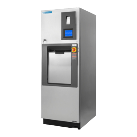
- Page 1 OPERATOR MANUAL AMSCO C Series Small Steam Sterilizers ® 16 x 16" (406 x 406mm) 20 x 20" (508 x 508 mm) • Prevacuum • Steam Flush Pressure Pulse (05/07/12) P129394-176...
- Page 2 Indications for Use ® The AMSCO C Series Small Steam Sterilizer is designed for sterilization of heat- and moisture-stable materials used in healthcare facilities and is available in two models: • Prevacuum – designed for sterilization of heat- and moisture- stable materials.
- Page 3 Factory-Set Cycles and Cycle Values The AMSCO C Series 16C and 20C Prevacuum Small Steam Sterilizer 16 x 16" (406 x 406 mm) and 20 x 20" (508 x 508 mm) is equipped with the following factory programmed sterilization cycles and cycle values (Table 1).
- Page 4 The AMSCO C Series 16CS and 20CS Steam Flush Pressure Pulse (SFPP) Small Steam Sterilizer 16" x 16" (406 x 406 mm) and 20" x 20" (508 x 508 mm) is equipped with the following factory programmed sterilization cycles and cycle values (Table 2).
- Page 5 Rack and Shelves * The liquid cycle is for non-patient contact use only. Table 6. Sterilizer Configurations AMSCO C Small Steam Sterilizers are offered in the following configurations: 16" Configurations 16 x 16 x 26" (406 x 406 x 660 mm) Single Door, Prevacuum 16 x 16 x 26"...
-
Page 6: Table Of Contents
TABLE OF CONTENTS Section Number Description Page Safety Precautions ........................1-1 Symbol Definitions ........................2-1 Installation Verification ......................... 3-1 Installation Checklist ..........................3-1 3.1.1 Service Clearance ........................3-1 3.1.2 Plumbing Services........................3-1 3.1.3 Electrical Service ........................3-2 3.1.4 Sterilizer Final Check ......................3-2 3.1.5 Cycle Operation........................ - Page 7 TABLE OF CONTENTS Section Number Description Page Power-Door Operation ........................5-14 5.10 Emergency Door Opening Procedure....................5-15 5.11 Emergency Stop Switch........................5-16 5.11.1 Emergency Stop Key......................5-17 5.11.2 Emergency Stop Guard ......................5-17 5.11.3 Emergency Stop Label ......................5-17 5.12 Optional Electric Steam Generator ....................
- Page 8 TABLE OF CONTENTS Section Number Description Page 7.5.5 Steam Generator Flush Cycle ....................7-21 7.5.6 Language ..........................7-22 7.5.7 Machine Number ........................7-23 7.5.8 Time Format .......................... 7-23 7.5.9 Print Format........................... 7-24 7.5.10 Audible Signals........................7-27 7.5.11 Units ............................7-28 7.5.12 Date Format ..........................
- Page 9 TABLE OF CONTENTS Section Number Description Page 9.3.1 Too Long To Close Door ....................... 9-11 9.3.2 Too Long To Open Door ....................... 9-12 9.3.3 Pressure In Chamber ......................9-13 9.3.4 Waste Temperature Probe Failure ..................9-13 9.3.5 Atmospheric Pressure Alarm....................9-14 9.3.6 Input/Output Board #1 Communication Failure ..............
- Page 10 LIST OF FIGURES Descrption Page Figure 4-1. Vented Closures ..........................4-8 Figure 5-1. AMSCO C Series Small Steam Sterilizer Control Components............5-1 Figure 5-2. Basic Controls............................. 5-3 Figure 5-3. Typical Out-Of-Cycle and In-Cycle Displays..................5-4 Figure 5-4. Alarm Display Examples ........................5-5 Figure 5-5.
- Page 11 LIST OF FIGURES Description Page Figure 7-6. Sample Full and Condensed Printouts ..................... 7-26 Figure 8-1. Remove Chamber Drain Strainer ....................... 8-3 Figure 8-2. Tear Paper in Printer .......................... 8-7 Figure 8-3. Remove Take Up Spool ........................8-7 Figure 8-4. Remove Paper From Spool ........................ 8-8 Figure 8-5.
- Page 12 Table 7-3. Required Feed Water Quality for Carbon Steel Steam Generators ..........7-20 Table 8-1. Preventive Maintenance ........................8-1 Table 10-1. Replacement Parts AMSCO C Series Small Steam Sterilizer 16 x 16" (406 x 406 mm) and 20 x 20” (508 x 508 mm) ......................10-8...
-
Page 13: Safety Precautions
SAFETY PRECAUTIONS ® The following Safety Precautions must be observed when operating or servicing this AMSCO C Series Steam Sterilizer. WARNING indicates the potential for personal injury and CAUTION indicates the potential for damage to equipment. For emphasis, certain Safety Precautions are repeated throughout the manual. It is important to review all Safety Precautions before operating or servicing the unit. - Page 14 FDA cleared product. Altering the equipment or using unapproved component’s may void STERIS’ warranty. DO NOT USE components that are not validated as part of the AMSCO C Series Sterilizer. WARNING – STERILITY ASSURANCE HAZARD: Load sterility may be compromised if the biological indicator or air leak test indicates a potential problem.
- Page 15 WARNING – STERILITY ASSURANCE HAZARD: (CONTINUED) According to AAMI standards, a measured leak rate greater than 1 mm Hg/minute (1.3 mbar/min) indicates a problem with the sterilizer. Refer the situation to a qualified service technician before using the sterilizer further. CAUTION –...
-
Page 16: Symbol Definitions
SYMBOL DEFINITIONS ® The following symbols appear on AMSCO C Series Small Steam Sterilizers and are provided here for reference. Table 2-1. Symbol Definitions Symbol Definition Symbol Definition Serial number of unit Transfer of heat, hot (located on sterilizer’s surface data plate) Protective earth (i.e.,... -
Page 17: Installation Verification
INSTALLATION VERIFICATION An Equipment Drawing showing all utility and space requirements was supplied with the sterilizer. Clearance space shown on the drawing is necessary for ease of installation and to assure proper operation and maintenance of equipment. Uncrating and Installation Instructions were also furnished with the sterilizer. -
Page 18: Electrical Service
❑ Electric single-phase service to the unit must be as specified on 3.1.3 Electrical Service the Equipment Drawing and on the Sterilizer’s Data Plate. ❑ Electric single-phase service requires a clearly marked disconnect with lockout/tagout capability located near the sterilizer and installed according to local codes. ❑... -
Page 19: Technical Specifications
3.2 Technical Specifications 3.2.1 Overall Size • 16" Sterilizer: 26" wide x 74-1/2" high x 35-3/4" deep (660 mm wide x 1892 mm high x 908 mm deep) • 20" Sterilizer: 30" wide x 74-1/2" high x 45-1/8" deep (762 mm wide x 1892 mm high x 1146 3.2.2 Weight •... -
Page 20: Techniques Of Sterilization
Optional (Supervisor Access Only) conditions have been met. NOTE: Contact STERIS for information on specific biological indicators recommended for use with this sterilizer. ® Table 4-1. AMSCO C Series Prevacuum Sterilizer Cycles Recommended Load Sterilize Sterilize Validation Cycles: Refer to Table 4 (page iii) Temp. - Page 21 ® Table 4-1. AMSCO C Series Prevacuum Sterilizer Cycles (Continued) Recommended Load Sterilize Sterilize Validation Cycles: Refer to Table 4 (page iii) Temp. Time Time Standard Recommended Quantities Immediate Use 270°F 4 Minutes 1 Minute Unwrapped instrument tray containing ST-8:2008 Prevac Cycle (132°C)
-
Page 22: Table 4-2. Amsco C Series Sfpp Sterilizer Cycles
Table 4-2. AMSCO C Series SFPP Sterilizer Cycles Recommended Load Sterilize Sterilize Validation Cycles: Refer to Table 4 (page iii) Temp. Time Time Standard Recommended Quantities SFPP Cycle 270°F 4 Minutes 30 Minutes Double-wrapped instrument trays, ST-8:2008 (132°C) porous and non-porous loads. -
Page 23: Immediate Use
Table 4-2. AMSCO C Series SFPP Sterilizer Cycles (Continued) Recommended Load Sterilize Sterilize Validation Cycles: Refer to Table 4 (page iii) Temp. Time Time Standard Recommended Quantities Gravity Cycle 270°F 25 Minutes 15 Minutes Fabric Packs ST-8:2008 (132°C) Immediate Use 270°F... -
Page 24: Biological Monitors
® 4.3.1 Biological Monitors Tests such as the Dart (Daily Air Removal Test) or Bowie-Dick are designed to document the removal of residual air from a sample challenge load. Run a Dart (Bowie-Dick test) cycle daily before processing any loads in a sterilizer equipped with prevacuum cycles. -
Page 25: Vacuum Leak Test
4.6 Recommendations Process all goods using prevacuum cycles. The AMSCO C Series small steam sterilizer is not a gravity displacement sterilizer. Run for the Sterilization gravity cycles only when qualified personnel have evaluated the Process loads and determined the efficacy of a gravity cycle. -
Page 26: Techniques Of Sterilization For Liquid Cycle
4.7 Techniques of Important: The liquid cycle is for non-patient contact use only. Sterilization for Refer to Table 4-3 for recommended Liquid cycle parameters. The Liquid Cycle recommended times indicated in Table 4-3 assume the use of vented bottles. Minimum recommended sterilization time (fourth WARNING –... -
Page 27: Recommendations For Sterilizing Liquids
4.8 Recommendations Important: Read the following paragraphs before sterilizing any liquids in your sterilizer. The liquid cycle is for non-patient contact for Sterilizing Liquids use only. WARNING – EXPLOSION Borosilicate glass is required because it is a superior glass capable HAZARD: The liquid cycle is of resisting thermal shock. -
Page 28: Component Identification
Generator Water Panel) Panel Supply Valve J AC KET Sight CHAMBER Glass Main Power Disconnect Switch Sterilizer Integral Electric Chamber Steam Generator Generator Drain Valve Figure 5-1. AMSCO C Series Small Steam Sterilizer Control Components Component Identification Operator Manual P129394-176... -
Page 29: General
5.1 General Use this manual to become familiar with control locations and functions before operating the sterilizer (refer to Figure 5-1). The controls for this sterilizer are contained within the control touch screen. Control touchpads appear on the screen as needed during each operation. -
Page 30: Figure 5-2. Basic Controls
Steam Supply Valve STATUS . . STANDBY TIME . . . 10:20:00 AM DATE . . . 2/20/94 Standby Screen Water Supply Valve Figure 5-2. Basic Controls NOTE: Touch-screen pads respond to very slight pressure, and only need to be pressed lightly. The sterilizer enters operating mode when the ON touchpad is pressed. -
Page 31: Control Displays
5.3 Control Control displays can be divided into two categories, those occurring when the sterilizer is “out-of-cycle” and those occurring when the Displays sterilizer is “in-cycle.” Typical out-of-cycle and in-cycle displays are shown in Figure 5-3: • Out-of-cycle displays are used to start cycles, or set up and adjust sterilizer operation. -
Page 32: Alarm Displays
5.4 Alarm Displays Alarm displays tell operators and technicians when the sterilizer is experiencing an abnormal condition. Alarm conditions can be caused by failure of utility supplies or sterilizer components. 9, T details the steps an operator can take ECTION ROUBLESHOOTING to solve most alarm conditions. -
Page 33: Operating End Control Panel
5.5 Operating End A sterilizer equipped with two doors will also be equipped with two control panels. The control panel at the loading door of the sterilizer Control Panel is referred to as the “operating end control” (OE control); the control panel located at the unloading door is referred to as the “non- operating end control”... -
Page 34: Figure 5-5. Control Panel
Cycle Printout Typical Menu Touch Screen Screen Operating End Control Panel Typical In-Cycle Screen Figure 5-5. Control Panel Component Identification Operator Manual P129394-176... -
Page 35: Cycle Selection Touch-Screen Pads
Details on individual cycles are in Section 6, Sterilizer Operation. The AMSCO C Series Small Steam Sterilizer control can be programmed to retain values for up to 12 separate cycles. User- defined cycle names can be entered for cycles 1 and 2 on the cycle selection screen. -
Page 36: Values Touch-Screen Pads
5.6.1 Values Touch-Screen The values touch-screen pads are accessed through the MENU Pads screen by pressing CHANGE CYCLE VALUES (refer to Figure 5-7). These pads are used for changing the operating values used in cycles, changing the cycles displayed on the cycle selection menus and for changing the operating settings of the sterilizer. -
Page 37: Abort Touch-Screen Pad
5.6.2 Abort Touch-Screen The Abort touch-screen pad is used to end a cycle before it finishes normally. A cycle only needs to be aborted if an abnormal condition or a control problem develops during the cycle. Pressing Abort causes the sterilizer chamber to depressurize (if pressurized), or Air Break (if in vacuum);... -
Page 38: Printer
5.7 Printer Refer to Figure 5-9 Printer records all cycle data on 2-1/4" (57 mm) wide single-ply paper. See 8, R for paper changing ECTION OUTINE AINTENANCE procedure. Printer functions controlled by touch-screen pads are as follows: • Paper Feed – (appears on typical In-cycle screen) Press to feed out paper from the roll stored inside the control. -
Page 39: Printouts
5.8 Printouts Refer to Figure 5-9 The printout reports useful information about each cycle the sterilizer runs. This includes the load number, which is a unique identifying code. Each load number is printed in the following format: • Two-digit month (e.g., April = 04) •... -
Page 40: Figure 5-9. Typical Printout
Cycle Type Cycle Start Time & Date Cycle Count Total Operator I.D. Machine Number & Serial Number Sterilize Temperature Control Overdrive Temperature Sterilize Time Dry Time Status Print Codes: Additional Status Print Codes: Conditioning F = Alarm (Failure) • Charge L = Leak Test (Vacuum or Hold) •... -
Page 41: Power-Door Operation
5.9 Power-Door The sterilizer door is operated at the foot pedal (refer to Figure 5-10). Operation • Pressing the foot pedal while the door is in the closed (up) position causes the door to open (lower). • Pressing the foot pedal while the door is in the open (lowered) position, causes the door to close (by raising). -
Page 42: Emergency Door Opening Procedure
5.10 Emergency Door This procedure should only be used when pressure remains in the sterilizer chamber, and the door cannot be opened normally Opening Procedure because the sterilizer has lost either electrical or water utilities. • Use emergency door opening procedure to retrieve a load WARNING –... -
Page 43: Emergency Stop Switch
5.11 Emergency Stop An emergency stop switch (Figure 5-12) is a safety feature designed to shut the sterilizer down completely in an emergency situation. Switch Pressing the emergency stop switch disconnects power to the door and valves, causing the door to stop and most valves to close, except S1 and S40, which are normally open, and will open when the emergency stop switch is pressed. -
Page 44: Emergency Stop Key
The emergency stop switch should be pressed only in an emergency situation such as • Safety mechanism fails to stop door when an obstruction is present • Steam enters the chamber when the door is open NOTE: An alarm is generated when the emergency stop switch is pressed. -
Page 45: Optional Electric Steam Generator
5.12 Optional Electric If a building steam source is not available, the sterilizer may be equipped with an electric steam generator. The generator Steam Generator automatically converts water to steam using electric heat. Electrically-heated steam created is then used to charge the sterilizer chamber. - Page 46 STATUS . .DRAIN 0:00 TEMP . . .00 F PRESS . . .0.0 inHg GENERATOR FLUSH PROJECTED CYCLE COMPLETION TIME: 12:20 MINUTES SECONDS PAPER STATUS ABORT FEED PRINT DRAIN – Boiler drain opens, allowing water to drain. NOTE: Heater elements are OFF during Drain phase. STATUS .
-
Page 47: Before Operating The Sterilizer
STERILIZER OPERATION Before Operating Operate sterilizer by referring to the appropriate cycle description in this section. The information in through the Sterilizer ECTION ECTION general instructions that apply to all cycle operations. 1. Press ON touch-screen pad on the sterilizer control display. WARNING –... -
Page 48: Figure 6-1. Utility Supply Valves And Basic Sterilizer Controls
STATUS . . STANDBY TIME . . . 10:20:00 AM DATE . . . 2/20/2011 Touch ON button to Advance to Cycle Selection Screen Steam Supply Valve Standby Screen STATUS . .DOOR CLOSED TEMP . . .128 F PRESS . . .0 PSIG PRESS "MORE CYCLES"... -
Page 49: Preparing Loads For Sterilization Cycles
Sterilization Cycles ® The AMSCO C Series Small Steam Sterilizer chamber holds commonly used wrapped or unwrapped instruments and equipment. 1. Wrappers may be made of 100% cotton, 140 thread count, two- ply fabric, and must be laundered; alternatively, use commercially available, non-woven disposable wrappers. -
Page 50: Unloading The Sterilizer
6.4 Unloading the At the end of a cycle, when end-of-cycle tone sounds and display shows the complete display (see below), open the chamber door. Sterilizer WARNING – BURN HAZARD: STATUS . .COMPLETE 00:00:00 • Sterilizer and shelves will be TEMP . -
Page 51: Loading Car Instructions: Loading
6.5 Loading Car NOTE: The loading car and transfer carriage are for use with the 20-inch Instructions: AMSCO C Series Small Steam Sterilizer, only. Loading 1. Open sterilizer door. 2. Verify that loading car is securely fastened to the transfer carriage. -
Page 52: Loading Car Instructions: Unloading
6.6 Loading Car NOTE: The loading car and transfer carriage are for use with the 20-inch Instructions: AMSCO C Series Small Steam Sterilizer, only. Unloading 1. Open sterilizer door. 2. Move transfer carriage forward until latches engage with track WARNING – BURN HAZARD: inside chamber. -
Page 53: Prevacuum Sterilizer Cycles
Figure 6-3. Sterilizer Chamber Equipped with Rack and Shelves 6.8 Prevacuum AMSCO C Series Small Steam Prevacuum Sterilizers are shipped with the factory-set cycles. Cycle descriptions are given in Sterilizer Cycles ECTION 6.9, through 6.14. -
Page 54: Table 6-1. Factory-Set Prevacuum Cycles And Cycle Values
Table 6-1. Factory-Set Prevacuum Cycles and Cycle Values The AMSCO C Series Prevacuum Small Steam Sterilizer is equipped with the following factory programmed prevacuum sterilization cycles and cycle values. Sterilize Sterilize Validation Cycles Temp. Time Time Recommended Load Standard 270°F... -
Page 55: Prevac Cycles
6.9 Prevac Cycles Prevac cycles, 270°F (132°C), are used for sterilizing double- wrapped instrument trays or fabric packs. Prevac cycles, 275°F (135°C), are used for sterilizing double-wrapped instrument trays only. Immediate use cycles must not be used with wrapped loads or fabrics. -
Page 56: Figure 6-5. Typical Prevacuum Cycle Printouts
270°F (132°C) Prevac, 270°F (132°C) Prevac, Full Load, Fabric Packs Immediate Use Cycle Printout Cycle Printout Figure 6-5. Typical Prevacuum Cycle Printouts 6-10 P129394-176 Operator Manual Sterilizer Operation... -
Page 57: Table 6-2. Factory-Set Gravity Cycles And Cycle Values
Table 6-2. Factory-Set Gravity Cycles and Cycle Values The AMSCO C Series Prevacuum Sterilizer is equipped with the following factory programmed gravity sterilization cycles and cycle values. Sterilize Sterilize Validation Cycles Temp. Time Time Recommended Load Standard Immediate Use Gravity 270°F... -
Page 58: Gravity Cycles
6.10 Gravity Cycles The Gravity cycle is used for sterilizing one or more unwrapped instrument trays containing non-porous items. WARNING – BURN HAZARD: 1. Refer to 6.1, B ECTION EFORE PERATING THE TERILIZER before running this cycle. • Sterilizer, rack/shelves and PAGE loading equipment will be hot 2. -
Page 59: Figure 6-7. Typical Gravity Cycle Printout
270°F (132°C) Gravity, Immediate Use Cycle Printout Figure 6-7. Typical Gravity Cycle Printout 6-14 P129394-176 Operator Manual Sterilizer Operation... -
Page 60: Table 6-3. Factory-Set Optional Liquid Cycle And Cycle Values
Table 6-3. Factory-Set Optional Liquid Cycle and Cycle Values The AMSCO C Series Sterilizer is equipped with the following optional factory programmed liquid sterilization cycle and cycle values. Sterilize Recommended Load Validation Cycles Sterilize Temp. Time Time (by Chamber Size) Standard 16 x 16"... -
Page 61: Liquid Cycle
6.11 Liquid Cycle This cycle is used for sterilizing liquids in vented closures. 1. Refer to 6.1, B ECTION EFORE PERATING THE TERILIZER WARNING – EXPLOSION before running this cycle. PAGE HAZARD: This sterilizer is not 2. See instructions for using the loading car/transfer carriage or designed to process flammable compounds. -
Page 62: Figure 6-9. Typical Printout Of A Liquid Cycle
Figure 6-9. Typical Printout of a Liquid Cycle 6-18 P129394-176 Operator Manual Sterilizer Operation... -
Page 63: Sfpp Sterilizer Cycles
6.12 SFPP Sterilizer AMSCO C Series SFPP Steam Sterilizers are shipped with factory-set cycles. The cycle sequence for these cycles is given in 6.13 Cycles ECTION (prevac and gravity cycles are described in 6.9, ECTION ECTION 6.10 6.11). Refer below, and to Table... -
Page 64: Table 6-4. Factory-Set Sfpp Sterilizer Cycles And Cycle Values
Table 6-4. Factory-Set SFPP Sterilizer Cycles and Cycle Values Sterilize Sterilize Validation Cycles Temp. Time Time Recommended Load Standard Double-wrapped instrument trays, porous and non- 270°F SFPP Cycle porous loads. Maximum ST-8:2008 (132°C) Minutes Minutes weight per tray, 25 lb (11.3 kg) 270°F SFPP Cycle... -
Page 65: Sfpp Cycles
6.13 SFPP Cycles SFPP cycles are designed for sterilizing both fabric packs and instrument trays. The cycle conditions loads at above-atmospheric pressure. WARNING – BURN HAZARD: NOTE: NOTE: Make sure items are clean and free of soil. • Sterilizer, rack/shelves, and loading car will be hot after 1. -
Page 66: Figure 6-11. Typical Printouts - 270°F Sfpp And 275° Sfpp Cycles
275°F (135°C) SFPP, 270°F (132°C) SFPP, Full Load, Instruments Trays Full Load, Fabric Packs Cycle Printout Cycle Printout Figure 6-11. Typical Printouts – 270°F SFPP and 275° SFPP Cycles 6-22 P129394-176 Operator Manual Sterilizer Operation... -
Page 67: Test Cycles
6.14 Test Cycles Test cycles are factory programmed on prevacuum sterilizers. These cycles are used to verify the sterilizer is functioning at optimum capability. Table 6-5. Test Cycles Test Cycles for Sterilize Validation All Units Temp. Sterilize Time Time Recommended Load Standard 270°F (132°C) 3 Minutes... -
Page 68: Dart (Bowie-Dick) Test
6.14.1 Dart (Bowie-Dick) Test This cycle is used to conduct a Dart (Bowie-Dick) test on sterilizers that use prevacuum cycles. This test is only applicable to sterilizers that use prevacuum cycles. For SFPP sterilizers, if the SFPP cycle is used exclusively, there is no need to run a daily Dart (Bowie-Dick) test. - Page 69 STERILIZE – Start of sterilize exposure is printed when the chamber reaches set temperature. Chamber temperature is printed every minute. Chamber is controlled at set point plus overdrive. FAST EXHAUST – Start of exhaust is printed and chamber is WARNING – BURN HAZARD: exhausted to 4 psig (0.28 bar).
-
Page 70: Figure 6-13. Dart (Bowie-Dick) Test Cycle Printout
Daily Air Removal Test (Dart) Cycle Printout Figure 6-13. Dart (Bowie-Dick) Test Cycle Printout 6-27 Sterilizer Operation Operator Manual P129394-176... -
Page 71: Vacuum Leak Test
6.14.2 Vacuum Leak Test This cycle is used for testing vacuum integrity of the sterilizer and piping. A Vacuum Leak Test cycle should be run on the sterilizer at least WARNING – BURN HAZARD: once each week. It should be one of the first cycles run for the day, •... -
Page 72: Figure 6-14. Typical Printout Of A Leak Test Cycle
Leak Test Cycle Printout Figure 6-14. Typical Printout of a Leak Test Cycle 6-29 Sterilizer Operation Operator Manual P129394-176... -
Page 73: Aborting Cycles
6.15 Aborting Cycles It may be necessary to end a processing cycle, possibly because the wrong cycle was selected or the sterilizer begins functioning incorrectly. A cycle can be aborted at any time by pressing the ABORT touch-screen pad. 1. Touch the ABORT touch-screen pad. WARNING –... -
Page 74: Cycle Graphs
6.16 Cycle Graphs These cycle graphs provide a visual representation of AMSCO C Series Small Steam Sterilizer cycles and their phases. Conditioning Sterilize Exhaust Fast Pulses Purge Charge Indicates Key Cycle Transition Points That Are Printed During Cycle Time * NOTE: 270°F (132°C) prevac cycle runs four conditioning vacuum pulses. 275°F (135°C) prevac runs three conditioning vacuum pulses. -
Page 75: Figure 6-17. Cycle Graph - Leak Test
Leak Testing Conditioning Pulse Pulse Stabil Leak Charge Purge Evacuate izing Test Indicates Key Cycle Transition Points That Are Printed During Cycle Time Figure 6-17. Cycle Graph – Leak Test Conditioning Sterilize Exhaust 3 Pulses & Steam Flushes Exhaust Flush Pulse Exhaust Flush Indicates Key Cycle... -
Page 76: Figure 6-19. Cycle Graph - Liquid Cycle
Conditioning Sterilize Slow Exhaust Purge Charge Indicates Key Cycle Transition Points That Are Printed During Cycle Time Figure 6-19. Cycle Graph – Liquid Cycle 6-33 Sterilizer Operation Operator Manual P129394-176... -
Page 77: Cycle And Control Value Programming
CYCLE AND CONTROL VALUE PROGRAMMING ® AMSCO C Series Small Steam Sterilizers are shipped with factory- set cycles, cycle values and control values programmed into the control (see Table Table 2 Table 3; page ii, iii and iii). Preset values can be changed to tailor the sterilizer to the operating environment in which it has been placed. -
Page 78: Change Cycle Values
7.2 Change Cycle Refer to Figures 7-1 through 7-3. Values 7.2.1 Overview 1. Press the ON touch screen pad, if the sterilizer is in STANDBY. The control advances to Status screen #1. 2. At screen #1, press the MENU touch screen pad, and the control advances to screen #2;... -
Page 79: Table 7-1. Adjustment Ranges For Cycle Values
Cycle values (sterilize temperature and time, and dry time) are adjustable within the limits shown in Table 7-1. • TEMP: For changing sterilize exposure temperature within the ranges shown. • STER: For changing the sterilization exposure time. Use number touchpads to enter a new value. Left and right arrow touchpads can be used to cursor through an existing value. -
Page 80: Step By Step Flowchart
Once all values for the selected cycle have been adjusted, press EXIT to save new values and return to the cycle selection display. Upon leaving Change Values the control prints the changed cycle values. 7.2.3 Step by Step Flowchart IMPORTANT: Applicable cycles have been validated to satisfy the requirements outlined... - Page 81 7-2, below, is a continuation of the flow chart in F 7-1. IGURE IGURE Comments: Important: Pressing EXIT causes the sterilizer to leave Change Values, saving any changes made to the point where EXIT was pressed. A printout of cycle values and the cycle count is provided by pressing PRINT...
- Page 82 Comments: Select Value • Press NAME touchpad to change cycle type • Press TEMP touchpad change sterilization exposure temperature. • Press STER touchpad to change Sterilization Exposure Time • Press DRY touchpad to change Drying Time TEMP, STER or DRY values can be entered or changed using the numeric touchpads.
-
Page 83: Entering Custom Cycle Names
7.3 Entering Custom Cycle Names EXAMPLE: CUSTOM NAMES are used to add descriptive text to the cycle selection buttons. • CLEAR button erases all text entered. • <- and -> buttons move the cursor position left or right. Figure 7-4. Enter or Change Custom Cycle Names Cycle and Control Value Programming Operator Manual P129394-176... -
Page 84: Change Time And Date
7.4 Change Time and Set time and date the sterilizer uses for all display and printout messages. Refer to Section 7.5.2, Lockout, on page 7-14 Date instructions on locking the time and date change feature. The current time and date appears on the Off/Standby (screen #0) and Status (screen #1) screens. - Page 85 b. If an incorrect number is entered, press TIME to start over, or use the cursor arrows at the bottom of the screen to back up to an incorrect number. TIME DATE ENTER TIME OR SELECT "DATE" TO SET ENTER TIME OR SELECT "DATE" TO SET TIME = 00:00 TIME = 00:00 EXIT...
- Page 86 TIME DATE ENTER TIME OR SELECT "DATE" TO SET ENTER TIME OR SELECT "DATE" TO SET TIME = 00:00 DATE = 00/00/00 (WEDNESDAY) EXIT <- -> c. Once the correct date has been entered, press EXIT to return to screen #1. NOTE: The day of the week is automatically understood and registered by the control.
-
Page 87: Change Machine Setup
7.5 Change Machine All changes are made to displayed settings using touch screens. No mechanical adjustments to the sterilizer are necessary. Setup Generally, the Setup options are used to change the way the sterilizer operates. The control has an Access Code Security feature. If the Access Code is enabled, all or some of these options can be secured or “locked out”... -
Page 88: Access Code
7.5.1 Access Code This setup option is used to control access to the adjustment functions of the sterilizer control. • When the Access Code is ON, a four-digit code must be entered before changing any locked-out functions. • Functions are selected for lock out by supervisor or operator. Enabling or Disabling the 1. - Page 89 SELECT GENERAL ACCESS CODE OPTION SELECT CODE REQUIRED TO SET CODE VALUE CODE CODE REQUIRED EXIT REQUIRED • CODE REQUIRED. Press CODE REQUIRED touchpad. The display advances to screen #35. This screen prompts for the entry of a four-digit code. a.
-
Page 90: Lockout
4. If the Access Code is already enabled and ACCESS CODE touchpad is pressed at the Change Machine Setup screen (#20), the display advances to screen #37 and the control prompts the user to enter the Access Code. a. Enter Code using the touchpads at the right of the screen. b. - Page 91 2. Press LOCKOUT touchpad on the Setup menu screen (#20). The display changes to show the Enter Access Code screen (#37). SELECT MACHINE SETUP TO REVIEW OR CHANGE LOCKOUT ACCESS UTILITIES LANGUAGE CODE CONTROL MACHINE TIME PRINT AUDIBLE NUMBER FORMAT FORMAT SIGNALS UNITS...
-
Page 92: Utilities Control
The lock graphic in the corner of the pad changes to reflect the lockout status. SELECT CYCLE TO LOCKOUT PREVAC PREVAC PREVAC PREVAC 273F 273F 273F 273F PREVAC PREVAC PREVAC PREVAC 273F 273F 273F 273F PREVAC PREVAC PREVAC PREVAC 273F 273F 273F 273F... - Page 93 STATUS . . UTILITIES SHUTDOWN TIME . . . 10:20:00 AM DATE . . . 2/20/94 TUESDAY RESTART: 6:00 AM WEDNESDAY UTILITIES WILL AUTOMATICALLY TURN ON AT RESTART TIME. PRESS ON TO TURN ON UTILITIES SOONER. UTILITIES WILL REMAIN ON UNTIL THE END OF THE CYCLE.
- Page 94 • GENERATOR FLUSH CONTROL allows set up and control of generator flush time and duration when manual utilities control is being used. (See Section 7.5.5, Steam Generator Flush Cycle, on page 7-21.) SHUTDOWN RESTART TIME TIME MONDAY 00:00 00:00 TUESDAY 00:00 00:00 WEDNESDAY...
- Page 95 Once the start up and shut off times have been selected, press EXIT to return to the Change Machine Setup screen (#20). See the following example to program automatic utilities control: Example: The sterilizer is to be used five days a week (Monday through Friday), with a daily start up time of 07:00 and a shut down time of 18:30.
-
Page 96: Steam Generator Flush And Drain Set Up
7.5.4 Steam Generator Flush If a building steam source is not available, the sterilizer may be equipped with an electric steam generator. The generator and Drain Set Up automatically converts water to steam using electric heat. The steam created is then used to power the sterilizer. Steam generators are highly susceptible to mineral scaling if the supplied water has any level of hardness. -
Page 97: Steam Generator Flush Cycle
7.5.5 Steam Generator The FLUSH TIME function shown on Screen #48 is active only Flush Cycle when Automatic Utilities Control has been enabled (see Section 7.5.3, Utilities Control, on page 7-16). The FLUSH DURATION set up function is always used when the sterilizer is equipped with an integral steam generator. -
Page 98: Language
(#39). Minimum flush duration time is five minutes. The control defaults to a five-minute flush duration as shipped. 7.5.6 Language The AMSCO C Series sterilizer is capable of operation with display screens and printouts in two of three languages. The factory default is ENGLISH. -
Page 99: Machine Number
7.5.7 Machine Number This set up is used to enter an identifying, two-character code into the sterilizer control. This code can be letters, numbers or a combination of both. The Machine Number code is printed out in the header for each cycle, allowing for processed goods to be traced back to a specific sterilizer when needed. -
Page 100: Print Format
SELECT TIME FORMAT AM/PM 24 HOUR EXIT 3. Select the appropriate time format by pressing one of the two touchpads in the lower half of the display. • AM / PM – This is the standard civilian time format. • 24 HOUR –... - Page 101 SELECT PRINT FORMAT FULL CONDENSED EXIT 3. Select the appropriate print format by pressing one of the two touchpads in the lower half of the display. • FULL – This is the standard format providing a status print for each phase of the cycle and status prints at the predetermined Print Interval.
-
Page 102: Figure 7-6. Sample Full And Condensed Printouts
Condensed Printout (Typical) Full Printout (Typical) Figure 7-6. Sample Full and Condensed Printouts 7-26 P129394-176 Operator Manual Cycle and Control Value Programming... -
Page 103: Audible Signals
7.5.10 Audible Signals This setup option allows the operator to adjust selected audible signals heard at the sterilizer control. Three signals can be adjusted. Touchpad and end of cycle signals can be adjusted to one of three volume levels or turned off. Only the volume level of the Alarm signal can be adjusted. -
Page 104: Units
7.5.11 Units This feature is used to select or change the units the sterilizer uses when displaying and printing chamber temperature and pressure. This function allows selection of either Fahrenheit or Celsius units for displaying and printing temperature. Pressure units can be changed between psig/inHg, mbar or psia. -
Page 105: Duplicate Print
SELECT DATE FORMAT = DAY = MONTH = 3 LETTER ABBREVIATION FOR MONTH = YEAR M-D-Y D-M-Y Y-M-D EXIT MON-D-Y D-MON-Y Y-MON-D • Y-M-D – Year-Month-Day • MON-D-Y – Month-Day-Year* • D-MON-Y – Day-Month-Year* • Y-MON-D – Year-Month-Day* * When selecting the format touchpads in the bottom row, MON = 3 letter abbreviation of the month. -
Page 106: Leaving Change Values
2. Press DUPLICATE PRINT touchpad on the Change Machine Setup screen. The display advances to screen #27. SELECT AUTOMATIC DUPLICATE PRINT STATUS DUPLICATE PRINT DUPLICATE EXIT PRINT 3. At screen #27, select the appropriate print option by pressing one of the touchpads in the lower half of the display. •... -
Page 107: Routine Maintenance
FDA cleared product. STERIS' warranty is void if components are used that are not approved. DO NOT USE components that are not validated as part of the AMSCO C Series Sterilizer. - Page 108 Table 8-1. Preventive Maintenance Periodic Maintenance Schedule for AMSCO C Series Small Steam Sterilizer Minimum Inspection Service Required Frequency 2.10 Sight Glass & Seal replace 2 x per year 2.11 Safety valve replace 2.12 Check valve replace 2.13 Steam outlet valve rebuild 2.14 Feed water valve rebuild...
-
Page 109: Daily Maintenance Procedures
8.2 Daily Maintenance Procedures 8.2.1 Check Printer Paper Check printer paper roll. Supply • A colored warning stripe is visible when roll is near its end. • 8.5.1, C , if a new paper ECTION HANGE RINTER APER roll is needed. 8.2.2 Clean Chamber Drain Important: The chamber drain strainer must be cleaned at least Strainer... -
Page 110: Weekly Maintenance Procedure: Flush Chamber Drain
8.3 Weekly Flush chamber drain as follows whenever the line becomes clogged: Maintenance 1. Turn off steam supply valve. Wait until jacket pressure is zero. Procedure: Flush Wait until chamber has cooled to room temperature. Chamber Drain 2. Remove chamber drain strainer (Figure 8-1). -
Page 111: Chamber Cleaning
8.4 Chamber Cleaning Due to differences in water quality, steam quality, frequency of use and boiler additives, no specific frequency interval is recommended for chamber cleaning. Operators must determine appropriate cleaning interval based on the local water conditions and chamber appearance. - Page 112 2. Wash the inside of the chamber and shelf assembly (plus any CAUTION – POSSIBLE other loading equipment) with a mild detergent solution such as EQUIPMENT DAMAGE: Liquid-Jet 2 Instrument Detergent or current equivalent product. • Lifting the chamber float Contact STERIS.) switch when cleaning the 3.
-
Page 113: Printer Maintenance
8.5 Printer Materials Required: Maintenance • Paper Roll (P129362-819) • Printer Ribbon (P150828-440) AMSCO C Series sterilizer users see 8.5, P ECTION RINTER AINTENANCE 8.5.1 Change Printer The printer paper roll should be changed whenever a colored stripe is visible on one or both edges of the printout paper. -
Page 114: Figure 8-4. Remove Paper From Spool
3. Pull off right end of spool and remove used paper roll from spindle. Figure 8-4. Remove Paper From Spool 4. Open access door and remove previous paper roll, gently pulling any remaining paper up and out of printer. Figure 8-5. Remove Remaining Previous Paper P129394-176 Operator Manual Routine Maintenance... -
Page 115: Figure 8-6. Insert New Paper Roll
5. Insert new paper roll. Figure 8-6. Insert New Paper Roll 6. Insert end of paper into printer slot just behind ink cartridge. Figure 8-7. Insert Paper Through Printer Slot Routine Maintenance Operator Manual P129394-176... -
Page 116: Figure 8-8. Press Paper Feed Touch Screen Button
7. Press PAPER FEED touch-screen pad on display until paper advances through printer and ink cartridge, exiting the front. Figure 8-8. Press Paper Feed Touch Screen Button 8-10 P129394-176 Operator Manual Routine Maintenance... -
Page 117: Figure 8-9. Insert Paper Into Take Up Spool
8. Continue pressing PAPER FEED (or pull paper gently) until about 18” (46cm) of paper hangs out of printer. Insert end of paper into slot of take-up spool, then replace right end of spool. Figure 8-9. Insert Paper Into Take Up Spool 9. -
Page 118: Change Printer Ink Cartridge
Reinstall take-up spool on magnetic idler. Manually roll up slack paper. Figure 8-11. Reinstall Take Up Spool 8.5.2 Change Printer Ink The printer ink cartridge should be changed as soon as the type on printouts is light or faded, and before printouts become difficult to Cartridge read. -
Page 119: Figure 8-13. Press On End Of Cartridge
2. Open access door, then press on right end of ink cartridge, until left end of cartridge pops out of the printer. Figure 8-13. Press On End of Cartridge 3. Slip cartridge off end of paper. Slip new cartridge over paper in the same way as before, making sure paper slides between ink cartridge housing and ink ribbon. -
Page 120: Figure 8-15. Press New Cartridge Into Place
4. Install left end of cartridge first, then push right end in as shown, snapping it into place. Figure 8-15. Press New Cartridge Into Place 5. Retighten ribbon by rotating wheel on left side of cartridge 1/4 turn. Then see 8.5.1, C , Steps ECTION... -
Page 121: Troubleshooting
TROUBLESHOOTING 9.1 General This section pictorially lists and describes all the possible alarm ® conditions which may occur when operating the AMSCO C Series Small Steam Sterilizer. If a problem occurs that is not described in this section, please call WARNING –... -
Page 122: Typical Alarm Printout
* ALARM ##/##/## PRESSURE IN CHAMBER F 10:07:23A 61.7C 2.34P Full Print Format Shown Figure 9-2. Typical Alarm Printout 9.1.2 Typical Alarm Printout When an alarm occurs the printer automatically generates a printout, typically listing alarm name, time alarm occurred, current chamber status and any associated sensor temperature. -
Page 123: Too Long In Exhaust
STATUS . . ALARM! 9.2.2 Too Long In Occurs if chamber TOO LONG IN EXHAUST does not exhaust to Exhaust CHAMBER: 00.0 F 0.0 psig 4 psig within the allotted time. STERILIZER WILL: • AUTOMATICALLY TRY TO COMPETE CYCLE • EXTEND EXHAUST TIME OPERAT0R INSTRUCTIONS: 1. -
Page 124: Too Long In Air Break
Alarm Description Screen with Instructions Service STATUS . . SERVICE INFORMATION: Too Long In Evacuation NOTE: This alarm has TOO LONG IN EVACUATION (Continued) two service help -> CHAMBER DID NOT REACH REQUIRED VACUUM LEVEL WITHIN ALLOTTED TIME screens. CAUSES AND CORRECTIONS: 1. -
Page 125: Under Sterilize Temperature
Alarm Description Screen with Instructions Service STATUS . . SERVICE INFORMATION: Too Long In Air Break TOO LONG IN AIR BREAK (Continued) -> CHAMBER DID NOT AIR BREAK VACUUM TO 1 PSIG WITHIN ALLOTTED TIME CAUSES AND CORRECTIONS: 1. AIR INLET FILTER PLUGGED ->... -
Page 126: Over Sterilize Temperature
Alarm Description Screen with Operator Instructions STATUS . . ALARM! 9.2.6 Over Sterilize Occurs if chamber OVER STERILIZE TEMPERATURE temperature exceeds Temperature CHAMBER: 00.0 F 0.0 psig the maximum sterilize temperature (Control STERILIZER WILL: temperature + • AUTOMATICALLY CONTINUE CYCLE NOTE: The control over-temperature OPERAT0R INSTRUCTIONS:... -
Page 127: Door Unsealed
Alarm Description Screen with Operator Instructions STATUS . . ALARM! 9.2.7 Door Unsealed Occurs if steam DOOR UNSEALED pressure in door seal CHAMBER: 00.0 F 0.0 psig drops below 5 psig. STERILIZER WILL: • AUTOMATICALLY ABORT CYCLE • EXHAUST OR AIR BREAK CHAMBER TO ATMOSPHERIC PRESSURE OPERAT0R INSTRUCTIONS: 1. -
Page 128: Exhaust Rate Too Fast
Alarm Description Screen with Service Instructions STATUS . . SERVICE INFORMATION: Chamber Pressure/ PRESSURE/TEMPERATURE FAILURE Temperature Failure -> PRESSURE OR TEMPERATURE OUTSIDE (Continued) NORMAL STEAM RANGE CAUSES AND CORRECTIONS: 1. CONTROL OUT OF CALIBRATION -> RECALIBRATE (CONTACT QUALIFIED SERVICE PERSON) 2. -
Page 129: Exhaust Rate Too Slow
Alarm Description Screen with Operator Instructions STATUS . . ALARM! 9.2.10 Exhaust Rate Occurs if liquid cycle EXHAUST RATE TOO SLOW exhaust rate is too slow. Too Slow CHAMBER: 00.0 F 0.0 psig STERILIZER WILL: • AUTOMATICALLY TRY TO COMPLETE CYCLE •... -
Page 130: Generator Drain Temperature Probe Failure Alarm
Screen with Operator Instructions 9.2.12 Generator Drain Temperature STATUS . . ALARM! GENERATOR DRAIN TEMPERATURE PROBE FAILURE Probe Failure Alarm CHAMBER: 70.0 F 0.0 psig GEN DRAIN: 300.0 RF STERILIZER WILL: • PREVENT NEW CYCLE FROM BEING STARTED UNTIL ALARM IS CLEARED OPERAT0R INSTRUCTIONS: 1. -
Page 131: Out-Of-Cycle Alarms
9.3 Out-of-Cycle The following alarm screens will appear only when the sterilizer is not processing a cycle. Alarms Alarm Description Screen with Operator Instructions STATUS . . ALARM! 9.3.1 Too Long To Occurs if door switch TOO LONG TO CLOSE DOOR does not make contact Close Door CHAMBER:... -
Page 132: Too Long To Open Door
Alarm Description Screen with Operator Instructions 9.3.2 Too Long To Occurs if door switch STATUS . . ALARM! does not open within the Open Door TOO LONG TO OPEN DOOR allotted time. CHAMBER: 00.0 F 0.0 psig STERILIZER WILL: • REMAIN IN ALARM CONDITION UNTIL DOOR IS OPENED OPERAT0R INSTRUCTIONS:... -
Page 133: Pressure In Chamber
Screen with Operator Instructions 9.3.3 Pressure In Occurs if 2 psig STATUS . . ALARM! Chamber PRESSURE IN CHAMBER pressure is sensed in the chamber. CHAMBER: 00.0 F 0.0 psig STERILIZER WILL: • AUTOMATICALLY EXHAUST CHAMBER TO ATMOSPHERIC PRESSURE OPERAT0R INSTRUCTIONS: 1. -
Page 134: Waste Temperature Probe Failure
Alarm Description Screen with Instructions Service Waste Temperature STATUS . . SERVICE INFORMATION: Probe Failure (Continued) -> RTD PROBE, WT, OUTPUT IS OUTSIDE NORMAL RANGE CAUSES AND CORRECTIONS: 1. LOOSE CONNECTION IN PROBE WIRING -> REPAIR 2. PROBE FAILED -> REPLACE ->... -
Page 135: Input/Output Board #1 Communication Failure
Alarm Description Screen with Operator Instructions 9.3.6 Input/Output The I/O board fails to STATUS . . ALARM! achieve communication Board #1 INPUT/OUTPUT BOARD #1 COMMUNICATION FAILURE with board #1, #2 or #3 Communication in the control box. Failure CHAMBER: 00.0 F 0.0 psig LOAD: 000.0 C... -
Page 136: Rom Failure
Alarm Description Screen with Operator Instructions 9.3.7 ROM Failure STATUS . . ALARM! Occurs if the Read Only ROM FAILURE memory on the main CHAMBER: 00.0 F 0.0 psig control circuit board fails. STERILIZER WILL: • AUTOMATICALLY ABORT CYCLE OPERAT0R INSTRUCTIONS: 1. -
Page 137: Emergency Stop Switch Pressed
Screen with Operator Instructions 9.3.10 Emergency The emergency stop STATUS . . ALARM! switch has been Stop Switch Pressed EMERGENCY STOP SWITCH PRESSED pressed. CHAMBER: 300.0 F 0.0 psig STERILIZER WILL: • STOP OPERAT0R INSTRUCTIONS: 1. SILENCE ALARM 2. CORRECT THE CAUSE FOR THE EMERGENCY STOP. -
Page 138: Sensor Alarms
Sensor Alarms The following alarm screens will appear (under alarm conditions) if the sterilizer is energized. The sensors are continually monitored whenever the sterilizer is in or out of cycle. Alarm Description Screen with Operator Instructions STATUS . . ALARM! 9.4.1 Water In Occurs if excess water WATER IN CHAMBER... -
Page 139: Too Long In Jacket Charge
Alarm Description Screen with Operator Instructions 9.4.2 Too Long In Occurs if jacket does STATUS . . ALARM! not reach set Jacket Charge TOO LONG IN JACKET CHARGE temperature within CHAMBER: 00.0 F 0.0 psig allotted time. JACKET: 00.0 F STERILIZER WILL: •... -
Page 140: Too Long To Unseal Door
Alarm Description Screen with Service Instructions Too Long To Seal Door STATUS . . SERVICE INFORMATION: (Continued) TOO LONG TO SEAL DOOR -> DOOR SEAL DID NOT REACH 10 PSIG WITHIN ALLOTTED TIME CAUSES AND CORRECTIONS: 1. SEAL PRESSURE SWITCH MALFUNCTION ->... -
Page 141: Chamber Pressure Transducer Failure
Alarm Description Screen with Operator Instructions 9.4.5 Chamber Occurs if chamber STATUS . . ALARM! pressure reading is Pressure Transducer CHAMBER PRESSURE TRANSDUCER FAIL- outside the normal Failure range. CHAMBER: 00.0 F 0.0 psig STERILIZER WILL: • AUTOMATICALLY ABORT CYCLE OPERAT0R INSTRUCTIONS: 1. -
Page 142: Jacket Temperature Probe Failure
Alarm Description Screen with Service Instructions Chamber Temperature STATUS . . SERVICE INFORMATION: Probe Failure CHAMBER TEMPERATURE PROBE FAILURE (Continued) -> RTD PROBE, CT, OUTPUT IS OUTSIDE NORMAL RANGE CAUSES AND CORRECTIONS: 1. LOOSE CONNECTION IN PROBE WIRING -> REPAIR 2. -
Page 143: Door Switch Failure
Alarm Description Screen with Instructions Service Jacket Temperature STATUS . . SERVICE INFORMATION: Probe Failure JACKET TEMPERATURE PROBE FAILURE (Continued) -> RTD PROBE, JT, OUTPUT IS OUTSIDE NORMAL RANGE CAUSES AND CORRECTIONS: 1. LOOSE CONNECTION IN PROBE WIRING -> REPAIR 2. -
Page 144: Door Seal A Switch Malfunction
Alarm Description Screen with Operator Instructions 9.4.9 Door Seal A Occurs if switched STATUS . . ALARM! neutral relay, Switch Malfunction DOOR A SEAL SWITCH MALFUNCTION associated with door CHAMBER: 00.0 F 0.0 psig seal A, closed switch fails. STERILIZER WILL: •... -
Page 145: Service Procedures
FDA cleared product. STERIS' warranty is void if components are used that are not approved. DO NOT USE components that are not validated as part of the AMSCO C Series Sterilizer. -
Page 146: Figure 10-1. Serviceable Components
Figure 10-1. Serviceable Components 10-2 P129394-176 Operator Manual Service Procedures... -
Page 147: Clean Strainers
Twist Tongue Location of Depressor or Seal Reference Similar Tool to Indicators Pry Out Seal Reference Indicators, Enlarged Location of Seal Reference Indicators Figure 10-2. Remove Door Seal Location of Seal Date Rear of Door Seal Information Figure 10-3. Location of Seal Lot Data and Reference indicators Clean Strainers 10.3... -
Page 148: Door Seal Replacement Procedure
Reassembly 1. Insert screen into strainer body. Ensure that no dirt or other particles remain in strainer body. 2. Replace and tighten hex plug. Use a new gasket if necessary. 3. Make certain all pipe connections are tight after assembly. 10.4 Door Seal Refer to Figures 10-2... -
Page 149: Steam Trap Replacement
10.5 Steam Trap Refer to Figure 10-4. Replacement Disassembly 1. Using a suitable wrench, unscrew and remove the cap and WARNING – BURN HAZARD: bellows assembly. • Allow sterilizer and 2. Remove seat from body using a hex socket wrench. accessories to cool to room temperature before performing 3. -
Page 150: Rebuild Solenoid Valves
10.7 Rebuild Refer to Figure 10-5. Solenoid Valves Solenoid valves can be rebuilt following the instructions included in the repair kit for the specific valve. Refer to Table 10-1. Replacement Parts, for correct kit number. Housing Solenoid Coil Stationary Core Connector Prongs Shading... -
Page 151: Recommended Spare Parts
10.9 Recommended To order replacement parts and/or supply products, proceed as follows: Spare Parts 1. Include the description and part/order number as listed in Table 10-1. Replacement Parts. 2. Include the model and serial numbers of your sterilizer on your order. -
Page 152: Table 10-1. Replacement Parts Amsco C Series Small Steam Sterilizer 16 X 16" (406 X 406 Mm) And 20 X 20" (508 X 508 Mm)
Table 10-1. Replacement Parts AMSCO C Series Small Steam Sterilizer 16 x 16" (406 x 406 mm) and 20 x 20” (508 x 508 mm) Schematic Part Schematic Part Designation Number Description Designation Number Description MTR1 P146660-338 DOOR MOTOR P093918-038... -
Page 154: Waste Products Disposal
10.10 Waste Products The following are waste materials associated with the sterilizer. When disposing of waste materials, be compliant with federal, state and Disposal local regulations. • Printer paper – recyclable. • Printer ribbon – not recyclable. • Water filters – not recyclable. •...
Need help?
Do you have a question about the C Series and is the answer not in the manual?
Questions and answers