Sign In
Upload
Manuals
Brands
Amsco Manuals
Laboratory Equipment
HC-800
Amsco HC-800 Manuals
Manuals and User Guides for Amsco HC-800. We have
2
Amsco HC-800 manuals available for free PDF download: Operator's Manual
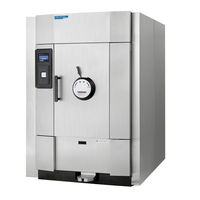
Amsco HC-800 Operator's Manual (176 pages)
Steam Sterilizers
Brand:
Amsco
| Category:
Laboratory Equipment
| Size: 7 MB
Table of Contents
Table of Contents
11
Number Description Page
12
Figure Number and Description Page
16
Safety Precautions
19
Symbol Definitions
23
Table 2-1. Symbol Definitions
23
Installation Verification
27
Installation Checklist
27
Service Clearance
27
Plumbing Services
27
Electrical Service
28
Sterilizer Final Check
28
Cycle Operation
28
Technical Specifications
29
Overall Exterior Dimensions W X H X L
29
Table 3-1. Sterilizer Overall Exterior Dimensions
29
Fully Loaded Weight
30
Table 3-2. Sterilizer Weights - Fully Loaded
30
Utility Requirements
31
Environmental Conditions
31
Techniques of Sterilization
33
General
33
Control Measure for Verifying Sterilization Process
34
Biological Monitors
34
Testing for Prevacuum Efficiency
34
Dart (Bowie-Dick) Test
34
Vacuum Leak Test
35
Techniques of Sterilization for Liquid Cycle
36
Table 4-1. Liquid Cycle Parameters
36
Recommendations for Sterilizing Liquids
37
Figure 4-1. Vented Closures
37
Component Identification
39
Figure 5-1. Component Identification (26 X 26" Sterilizer Shown)
39
General
40
Sterilizer and Cycle Controls
40
Sterilizer Key Switch Operation
41
Figure 5-2. Sterilizer Key Switch
41
Control
42
Figure 5-3. Typical Out-Of-Cycle Display
42
Figure 5-4. Typical In-Cycle and In-Cycle Status Display
42
Alarm Displays
43
Operating End Control Panel
43
Cycle Selection Touch Pads
44
Figure 5-6. Cycles Screen
44
Figure 5-7. Test Cycle Screen
44
Figure 5-8. Out-Of-Cycle Status Screen
44
Change Values Control Screens
45
Abort Touch-Screen Button
46
Printer
47
Figure 5-12. Thermal Printer
47
Figure 5-13. Accessing Duplicate Print
47
Printouts
48
Figure 5-14. Typical Printout
48
Vertical-Sliding Door Operation (26 X 26" Sterilizers)
49
Horizontal-Sliding Door Operation (26 X 37.5" and 26 X 61" Sterilizers)
49
Hinged-Door Operation
50
Figure 5-15. Hinged-Door Operation
50
Sterilizer Operation
51
Before Operating the Sterilizer
51
Table 6-1. Factory-Set Cycles and Cycle Values for Evolution Prevacuum Sterilizer
52
Table 6-2. Factory-Set Cycles and Cycle Values for Evolution SFPP Sterilizer
53
Table 6-3. Test Cycles
54
Table 6-4. Recommended Loads by Sterilizer Chamber Size
54
Table 6-6. Sterilizer Chamber Volume
55
Preparing Loads for Sterilization Cycles
56
Guidelines for Placement of Various Loads
56
Loading Cart and Transfer Carriage Instructions: Loading
57
Figure 6-1. Transfer Carriage and Loading Cart
57
Figure 6-2. Loading Goods into Sterilizer Chamber
58
Loading Cart and Transfer Carriage: Unloading
59
Floor Loading Sterilizer Loading and Unloading
60
Table 6-7. Cart Capacity and Load Capacity
60
Unloading the Sterilizer
61
Figure 6-3. Loading Floorloader Sterilizer Chamber
61
Figure 6-4. Cycles Screen -Door Interlock Feature Enabled
62
Prevacuum Sterilizer Cycle
63
Table 6-8. Factory-Set Prevacuum Cycles and Cycle Values
64
Prevac Cycles
65
Table 6-9. Factory-Set Gravity Cycles and Cycle Values
68
Gravity Cycles
69
Figure 6-8. Typical Gravity Cycle Printouts
70
Table 6-10. Factory-Set Liquid Cycle and Cycle Values
72
Liquid Cycle
73
Figure 6-10. Typical Printout of a Liquid Cycle
74
SFPP Sterilizer Cycles
75
Table 6-11. Factory-Set Cycles and Cycle Values SFPP Sterilizer
76
SFPP Cycles
77
Figure 6-12. Typical Printouts - SFPP Cycles (270°And 275°F)
78
Test Cycles
80
Table 6-12. Test Cycles
80
Dart (Bowie-Dick) Test
81
Figure 6-14. Dart (Bowie-Dick) Test Cycle Printout
83
Vacuum Leak Test
84
Figure 6-15. Vacuum Leak Test Cycle Printout
85
Aborting Cycles
86
Emergency Manual Exhaust
88
Figure 6-16. Air Manifold
88
Cycle Graphs
89
Figure 6-17. Cycle Graph: Prevacuum and Bowie-Dick (Dart) Cycles
90
Figure 6-18. Cycle Graph: Gravity Cycle
91
Figure 6-19. Cycle Graph: Liquid Cycle
92
Figure 6-20. Cycle Graph: Steam Flush Pressure Pulse (SFPP) Cycle
93
Figure 6-21. Cycle Graph: Leak Test Cycle
94
Cycle and Control Value Programming
95
Cycle Values
96
Table 7-1. Factory-Set Cycles and Cycle Values for Evolution Prevacuum Sterilizer
96
Table 7-2. Factory-Set Cycles and Cycle Values for Evolution SFPP Sterilizer
97
Change Values
98
Table 7-3. Adjustment Ranges for Cycle Values
99
Change Cycle Values
100
Change Cycle Values Procedure
100
Change Time and Date
102
Set Time Format
102
Set Time
103
Date Format
106
Set Date
107
Change Machine Setup
109
Table 7-4. Change Machine Setup
109
Change Password
110
Future Use
111
Utility Control
112
Utility Control Summary
117
Utility Control with Integral Electric Steam Generator
118
Language
119
Machine Number
121
Print Options
123
Audible Signals
125
Units
127
Leaving Machine Setup
128
Routine Maintenance
129
Preventive Maintenance
129
Daily Maintenance
130
Figure 8-1. Remove and Clean Chamber Drain Strainer
130
Figure 8-2. Thermal Printer
130
Figure 8-3. Positioning Paper Roll
131
Weekly Maintenance
132
Clean Chamber
133
Troubleshooting
135
General
135
Typical Alarm Screen
136
Typical Alarm Printout
137
In-Cycle Alarms
137
Too Long in Charge
137
Table 9-1. Operator Troubleshooting - In-Cycle Alarms
137
Too Long in Evacuation
139
Too Long in Air Break
140
Under Sterilize Temperature
140
Over Sterilize Temperature
141
OE/NOE Door Unsealed
142
Chamber Pressure/Temperature Failure
143
Recorder Deviation Alarm
143
Out-Of-Cycle Alarms
146
Too Long to Close OE (or NOE) Door
146
Table 9-2. Operator Troubleshooting - Out-Of-Cycle Alarms
146
Too Long to Open OE (or NOE) Door
147
Pressure in Chamber
147
Waste Temperature Probe Failure
148
RTC Failure
148
Emergency Stop Button Pressed
149
Input/Output Fault - Module #X
149
Sensor Alarms
150
Table 9-3. Operator Troubleshooting - Sensor Alarms
150
Too Long to Seal OE/NOE Door
155
Exhaust Rate too Slow
155
Exhaust Rate too Fast
156
Water Conservation System Alarms
157
Tank Water too Hot (Green Machine)
157
Too Long to Fill Tank
158
(Green Machine)
158
Tank Water too Hot
159
Too Long to Fill
160
Operating System Alarms
161
Invalid os Revision
161
Invalid PLC Revision
162
Invalid HMI Revision
163
Service Procedures
165
General
165
Air Filter Replacement
165
Clean Jacket Steam Strainers
166
Door Seal Replacement Procedure
166
Floorloading Sterilizer Door Seal Replacement Procedure
170
Steam Trap Replacement
171
Clean or Replace Piping Check Valves
171
Table 10-1. Recommended Spare Parts
171
Safety Valve Test
172
Recommended Spare Parts
172
Waste Products Disposal
175
Advertisement
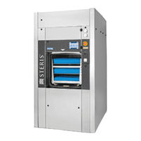
Amsco HC-800 Operator's Manual (146 pages)
Medium Steam Sterilizers
Brand:
Amsco
| Category:
Laboratory Equipment
| Size: 7 MB
Table of Contents
Table of Contents
7
Safety Precautions
13
Symbol Definitions
17
Table 2-1. Symbol Definitions
17
Installation Verification
23
Installation Checklist
23
Service Clearance
23
Plumbing Services
23
Electrical Service
24
Sterilizer Final Check
24
Cycle Operation
24
Technical Specifications
25
Overall Exterior Dimensions W X H X L
25
Fully Loaded Weight
25
Table 3-1. Sterilizer Overall Exterior Dimensions
25
Table 3-2. Sterilizer Weights - Fully Loaded
25
Utility Requirements
26
Environmental Conditions
26
Techniques of Sterilization
27
General
27
Control Measure for Verifying Sterilization Process
28
Biological Monitors
28
Table 4-1. Cycle Information
28
Table 4-2. Chamber Volume by Sterilizer Chamber Size
28
Testing for Prevacuum Efficiency
29
Bowie-Dick Test
29
Vacuum Leak Test
30
Component Identification
31
Figure 5-1. Component Identification (660 X 660 MM Sterilizer Shown)
31
General
32
Main Sterilizer and Cycle Controls
32
Figure 5-2. Sterilizer Key Switch and Countdown to Shutdown Timer
33
Control
34
Figure 5-3. Typical Out-Of-Cycle Display
34
Figure 5-4. Typical In-Cycle and In-Cycle Status Display
34
Alarm Displays
35
Operating End Control Panel
35
Cycle Selection Touch Pads
36
Figure 5-6. Cycle Selection Screen
36
Figure 5-7. Test Cycle Screen
36
Figure 5-8. Out-Of-Cycle Status Screen
36
Change Values Control Screens
37
System Shutdown Button
38
Figure 5-11. Standby Screen
38
Figure 5-12. Shutdown Confirmation
38
Abort Touch-Screen Button
39
Printer
40
Figure 5-14. Printer Features (Printer Door Open)
40
Figure 5-15. Access Duplicate Print Function
40
Printouts
41
Figure 5-16. Typical Printout
42
Vertical-Sliding Door Operation (660 X 660 MM Sterilizers)
43
Horizontal-Sliding Door Operation (660 X 950 MM Sterilizers)
43
Sterilizer Operation
45
Before Operating the Sterilizer
45
Table 6-1. Prevacuum Sterilizer Cycle Values
46
Table 6-2. Test Cycles
46
Table 6-3. Sterilizer Chamber Volume
46
Preparing Loads for Sterilization Cycles
47
Guidelines for Placement of Various Loads
47
Loading & Unloading the Sterilizer
48
Figure 6-1. Loading Trolley and Carrier
49
Figure 6-2. Loading Goods into Sterilizer Chamber
50
Loading Trolley and Carrier Instructions: Unloading
51
Prevacuum Sterilizer Cycle
52
Table 6-4. Prevacuum Sterilizer Cycles and Cycle Values
52
Prevac Cycle Operation
53
Figure 6-3. Prevacuum Cycle Printouts (134°C [273°F] and 121°C [250°F])
56
Table 6-5. Factory-Set Liquid Cycle and Cycle Values
58
Liquid Cycle
59
Figure 6-5. Typical Printout of a Liquid Cycle
60
Test Cycles
61
Bowie-Dick Test
63
Figure 6-6. Bowie-Dick Test Cycle Printout
65
Vacuum Leak Test
66
Figure 6-7. Leak Test Cycle Printout
67
Aborting Cycles
68
Cycle Graph
70
Figure 6-8. Cycle Graph: Prevacuum Cycle - 134°C (273°F) and 121°C (250°F)
71
Figure 6-9. Cycle Graph: Liquid Cycle
72
Cycle and Control Value Programming
73
Cycle Values
74
Table 7-1. Prevacuum Sterilizer Cycle Values
74
Table 7-2. Test Cycles
74
Table 7-3. Sterilizer Chamber Volume
74
Change Values
75
Change Cycle Values
76
Overview
76
Change Cycle Values Procedure
77
Change Time and Date
79
Set Time Format
79
Set Time
80
Date Format
83
Set Date
84
Change Machine Setup
86
Table 7-4. Change Machine Setup
86
Utility Control
87
Utility Control Summary
92
Utility Control with Integral Electric Steam Generator
93
Language
94
Machine Number
96
Print Options
98
Audible Signals
100
Units
102
Leaving Machine Setup
103
Routine Maintenance
105
Preventive Maintenance Schedule
105
Table 8-1. Preventive Maintenance Schedule for Amsco
105
Daily Procedures
107
Clean Chamber Drain Strainer
107
Clean Chamber
108
Weekly Maintenance: Flush Chamber Drain
109
Maintenance as Required
109
Change Printer Paper Roll
109
Figure 8-1. Open Printer Door
109
Figure 8-2. Printer Components (Printer Door Open)
110
Figure 8-3. Tear Printer Paper
110
Figure 8-4. Insert New Paper Roll
111
Figure 8-5. Insert Paper Behind Printer Ink Cartridge
111
Figure 8-6. Press Paper Freed Button to Advance Paper
112
Figure 8-7. Coil Paper Onto Take-Up Spool
112
Figure 8-8. Reinstall Take-Up Spool
112
Change Printer Ink Cartridge
113
Figure 8-9. Remove Ink Cartridge from Printer
113
Figure 8-10. Slip Cartridge Onto Printer Paper
113
Troubleshooting
115
General
115
Typical Alarm Screen
116
Figure 9-1. Alarm and Alarm Detail Screen Features
116
Typical Alarm Printout
117
In-Cycle Alarms
117
Too Long in Charge
117
Figure 9-2. Typical Alarm Printout
117
Table 9-1. Operator Troubleshooting - In-Cycle Alarms
117
Too Long in Exhaust
118
Too Long in Evacuation
119
Too Long in Air Break
120
Under Sterilize Temperature
120
Over Sterilize Temperature
121
OE/NOE Door Unsealed
121
Chamber Pressure/Temperature Failure
122
Recorder Deviation Alarm
122
Steam Utility Failure
123
Water Utility Failure
123
Air Utility Failure
124
Out-Of-Cycle Alarms
125
Too Long to Close OE (or NOE) Door
125
Table 9-2. Operator Troubleshooting - Out-Of--Cycle Alarms
125
RTC Failure
127
UPS Battery Low
129
Sensor Alarms
130
Table 9-3. Operator Troubleshooting - Sensor Alarms
130
Too Long to Seal OE/NOE Door
135
Exhaust Rate too Slow
135
Exhaust Rate too Fast
136
Generator Alarm
136
Service Procedures
137
General
137
Air Filter Replacement
137
Clean Jacket Steam Strainers
138
Door Seal Replacement Procedure
138
Figure 10-1. Door Seal Replacement, 660 X 660 MM (26 X 26") Sterilizers
140
Figure 10-2. Door Seal Replacement, 660 X 950 MM (26 X 37.5") Sterilizers
141
Steam Trap Replacement
142
Clean or Replace Piping Check Valves
142
Figure 10-3. Steam Trap
142
Table 10-1. Recommended Spare Parts
142
Safety Valve Test
143
Recommended Spare Parts
143
Figure 10-4. Evolution Sterilizer Piping Schematic
145
Waste Products Disposal
146
Advertisement
Related Products
Amsco HC-900
Amsco HC-1200
Amsco HC-1500
Amsco HC-600
Amsco HC-1000
Amsco HC-2000
Amsco HC-3000
Amsco 110LS
Amsco 250LS
Amsco 36 H
Amsco Categories
Laboratory Equipment
Medical Equipment
Washer
Light Fixture
More Amsco Manuals
Login
Sign In
OR
Sign in with Facebook
Sign in with Google
Upload manual
Upload from disk
Upload from URL