Advertisement
Please read & check through these instructions carefully before
This product is designed to conform to the latest safety regulations and we hope you will be happy
with your purchase. Whist every effort is made to ensure this product reaches you in good
condition, in the unlikely event you find a problem with any component, please do not attempt to
assemble – and contact your retailer. As you will appreciate, we cannot accept liability for damage
CLEANING: - A damp cloth should be sufficient to keep this product in good order. Please do not attempt to use
abrasive cleaning materials, as this will incur damage. Thank you for choosing our product. We hope you will be happy
with your purchase.
Assembly Instructions
TOP
LH SIDE
BOTTOM
PLINTH
8 x cam bolt
8 x cam
6 x rear panel
connector
proceeding with assembly.
once an attempt to assemble has been made.
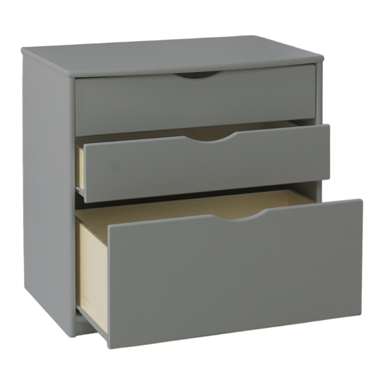
3 Drawer Chest
RH SIDE
A
C
- 1 -
COMPONENTS;
1 x RH side
1 x LH side
1 x Bottom
1 x bottom plinth
1 x Top
2 x 3mm thick back
panels
Doors in Box 2
3 X Drawer base
1 x box fittings
(contents as below)
Tool required
12 x 8mm
dowel (pre-
inserted into
panels)
1 x"H"
profile rear
D
panel
connector
B
Advertisement
Table of Contents

Related Manuals for Scallywag Kids 3 Drawer Chest

Summary of Contents for Scallywag Kids 3 Drawer Chest
- Page 1 Assembly Instructions 3 Drawer Chest COMPONENTS; 1 x RH side 1 x LH side 1 x Bottom 1 x bottom plinth LH SIDE 1 x Top 2 x 3mm thick back panels RH SIDE Doors in Box 2 BOTTOM 3 X Drawer base...
- Page 2 Bottom sid e bottom P linth . Insert cam bolt A to 5mm holes on sides. . Press fit plinth into underside of bottom, Insert cam C to 15mm holes on top & bottom. locating pre-inserted plinth dowels (B) into holes in bottom panel.
- Page 3 . Fix the white rear panel connectors by placing the small white lip between the back panel and the unit, then screwing diagonally into the unit as shown opposite. Position the connectors: two to the top and bottom and one into each side at approximately half way.
Need help?
Do you have a question about the 3 Drawer Chest and is the answer not in the manual?
Questions and answers