Table of Contents
Advertisement
Quick Links
www.voltech.com
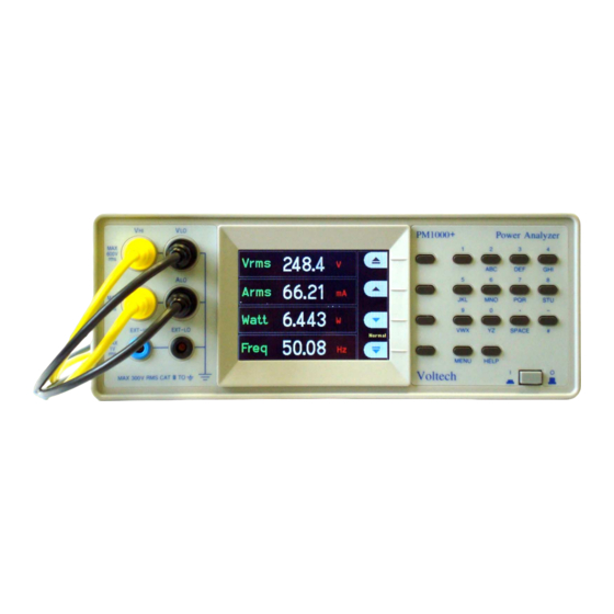
PM1000+
P
A
OWER
NALYZER
U
M
SER
ANUAL
Need help?
Thank you for choosing to use this Voltech Power Analyzer. It has
been designed to be safe and easy to use.
Should you experience any difficulty during the set up or use of any
Voltech product, or are unsure of any of their features or abilities,
please do not hesitate to contact either your local supplier or visit
our applications support center at www.voltech.com
Voltech Instruments Inc.
Voltech Instruments Ltd.
11637 Kelly road, Suite 306
148 Harwell Business Centre
Fort Myers, FL33908
Didcot, Oxon, OX11 0RA
U.S.A.
U.K.
Tel: 239 437 0494
Tel: +44 1235 834555
Fax: 239 437 3841
Fax: +44 1235 835016
sales@voltech.com
sales@voltech.co.uk
PM1000+ Power Analyzer User Manual
© Voltech 2007
Page
I
Advertisement
Table of Contents

Subscribe to Our Youtube Channel
Related Manuals for Voltech PM1000+


Summary of Contents for Voltech PM1000+
- Page 1 NALYZER ANUAL Need help? Thank you for choosing to use this Voltech Power Analyzer. It has been designed to be safe and easy to use. Should you experience any difficulty during the set up or use of any Voltech product, or are unsure of any of their features or abilities, please do not hesitate to contact either your local supplier or visit our applications support center at www.voltech.com...
- Page 2 Voltech Instruments is committed to a policy of continuous product development. Hence product specification and the information given in this manual are subject to change without notice. No part of this publication may be reproduced, stored in a retrieval system, or transmitted in any form, or by means electronic, mechanical photocopying, recording or otherwise, without prior written permission of Voltech Instruments.
- Page 3 Solo personale qualificato può installare questo strumento, dopo la lettura e la comprensione di questo manuale. Se esistono dubbi consultate il vostro rivenditore. IMPORTANT: Please consult the safety information section of this user manual before installation and use. PM1000+ Power Analyzer User Manual © Voltech 2007 Page III...
- Page 4 Page IV © Voltech 2007 PM1000+ Power Analyzer User Manual...
-
Page 5: Table Of Contents
4. The Menu System..................4-1 4.1. Navigation....................... 4-1 4.2. Menu Items ..................... 4-1 4.3. Main Menu ...................... 4-1 4.4. Measurements....................4-1 4.5. Modes......................4-2 Select Mode....................4-2 Ballast Setup....................4-2 PM1000+ Power Analyzer User Manual © Voltech 2007 Page V... - Page 6 5.1. Overview......................5-1 5.2. Command Listing .................... 5-1 5.3. Communications examples................5-5 Basic selection and returning of result............5-5 Harmonics...................... 5-6 Standby power ....................5-6 Inrush......................5-7 6. Specification ....................6-1 Page VI © Voltech 2007 PM1000+ Power Analyzer User Manual...
- Page 7 7.3. Obtaining Service and Applications Support ........... 7-2 7.4. Updating Firmware..................7-2 8. Safety Information..................8-1 8.1. Safety Features ....................8-1 8.2. Safety Instructions ..................8-1 8.3. Declaration of Conformity................8-2 PM1000+ Power Analyzer User Manual © Voltech 2007 Page VII...
- Page 8 Page VIII © Voltech 2007 PM1000+ Power Analyzer User Manual...
-
Page 9: Introduction
EATURES BILITIES The Voltech PM1000+ is a powerful and versatile precision power analyzer. Designed to provide clear and accurate measurements of electrical power and energy on all electrical products, the PM1000+ is both an easy to use bench instrument and a fast and programmable automatic test interface. -
Page 10: Package Contents
ACKAGE ONTENTS The following items are supplied with your PM1000+. Please check that you have every item and report any missing items to your Voltech supplier as soon as possible • PM1000+ Power Analyzer • Certificate of Conformance and Calibration •... -
Page 11: Quick Start
The PM1000+ will start its power up sequence. This takes approximately one minute. During power up you will see the PM1000+’s serial number and last calibration date. 5. The instrument is now ready for use PM1000+ Power Analyzer User Manual © Voltech 2007 Page 2-1... -
Page 12: Connecting To The Product Under Test
Always use good quality safety cables as supplied and check that they are not damaged before use. V HI V LO To ac To load supply live neutral A HI To load neutral A HI To supply neutral Page 2-2 © Voltech 2007 PM1000+ Power Analyzer User Manual... -
Page 13: Default Measurements
Quick Start The simplest and safest way to make a connection to the product under test is to use a Voltech Break Out Box. This provides a line socket for connection of the product and 4 x 4mm sockets for direct connection to the PM1000+ terminals as described above. -
Page 14: Navigating The Menu System
To return to the measurement display at any time, simply press the MENU key again. With the menu system active, the 4 soft keys to the right of the display may be used to navigate and select options. MENU KEYS Page 2-4 © Voltech 2007 PM1000+ Power Analyzer User Manual... -
Page 15: Menu Keys
"# 4. (Option). Move the measurement 5. Press OK. To remove a measurement, select it and press Hint: To restore the default list, see the User Configuration Menu. PM1000+ Power Analyzer User Manual © Voltech 2007 Page 2-5... -
Page 16: Key Shortcuts
UICK TART 2.7. HORTCUTS Display freeze: Press SPACE Display graph: Press YZ Print: Press VWX Local control (from remote): Press # Page 2-6 © Voltech 2007 PM1000+ Power Analyzer User Manual... -
Page 17: Using Voltage And Current Transducers
Convenience of connection – E.g. using a clamp-on current transformer, with jaws that open, for quick connection in a fixed wiring loom. • The effect of the transducer on the circuit. PM1000+ Power Analyzer User Manual © Voltech 2007 Page 3-1... -
Page 18: To Connect A Simple Current Transfomer
IMPLE URRENT TRANSFOMER To use a conventional current transformer (CT) like the Voltech CL series (or any other transducer with a current output), connect the normal AHI and ALO inputs of the PM1000+ to the outputs of the current transformer. Follow the manufacturer’s instructions for the safe use and installation of the transducer. -
Page 19: To Connect An External Resistive Shunt
This is well within the 1V rating of the PM1000+’s External Current Inputs 2. Connect the shunt in series with the load and to the EXT-HI and EXT-LO inputs as shown. PM1000+ Power Analyzer User Manual © Voltech 2007 Page 3-3... - Page 20 Press ’MENU’ Select "# ‘Inputs’ and press "# Select ‘Scaling’ and press "# Select ‘Amps’ and press Use the delete key to clear the entry. Type the new scale factor (e.g.10) Page 3-4 © Voltech 2007 PM1000+ Power Analyzer User Manual...
-
Page 21: To Connect A Transducer With A Voltage Output
"# ‘Inputs’ and press Select "# ‘Scaling’ and press "# Select ‘Amps’ and press Use the delete key to clear the entry. Type the new scale factor (e.g. 0.1) Press PM1000+ Power Analyzer User Manual © Voltech 2007 Page 3-5... -
Page 22: To Connect A Voltage Transformer / Transducer
Type the new scale factor (100) Press Press ‘MENU’ to return to the measurement display. The PM1000+ is now ready to make measurements using a VT. Page 3-6 © Voltech 2007 PM1000+ Power Analyzer User Manual... - Page 23 SING OLTAGE AND URRENT RANSDUCERS PM1000+ Power Analyzer User Manual © Voltech 2007 Page 3-7...
- Page 24 SING OLTAGE AND URRENT RANSDUCERS Page 3-8 © Voltech 2007 PM1000+ Power Analyzer User Manual...
-
Page 25: The Menu System
To restore the default list, see the User Configuration Menu. For harmonics only, there are further choices: • Enable / Disable • Sequence - All or odd harmonics only • Range - The maximum harmonic (up to 50) PM1000+ Power Analyzer User Manual © Voltech 2007 Page 4-1... -
Page 26: Modes
Choose the starting current range. Start with the maximum range and then set the mode and make measurements. Choose a lower range with the soft-keys for more accuracy once you begin to make measurements. Page 4-2 © Voltech 2007 PM1000+ Power Analyzer User Manual... -
Page 27: Standby Power Setup
PM1000+ display the true scaled measurements. "# Select Volts or Amps and press to enter the scale factor. See the Chapter ‘Using External Voltage and Current Transducers’ for further information. PM1000+ Power Analyzer User Manual © Voltech 2007 Page 4-3... -
Page 28: Frequency Source
Set up the graphical displays of the PM1000+ "# Select the graph type using the keys and press for options. HINT: Use the ‘YZ’ key to toggle between graphic and numeric displays. Page 4-4 © Voltech 2007 PM1000+ Power Analyzer User Manual... -
Page 29: Waveform Graph
! ! ! ! to confirm. 9600, 19200 (default) and 38400 are available. The PM1000++ uses hardware handshaking (RTS / CTS) with no parity, 8 data bits and 1stop bit (N,8,1). PM1000+ Power Analyzer User Manual © Voltech 2007 Page 4-5... -
Page 30: Gpib Address
Clock Setup These options may be used to check or set the PM1000+’s internal clock. To select a menu item, use the "# keys and then press for detailed options. Page 4-6 © Voltech 2007 PM1000+ Power Analyzer User Manual... -
Page 31: View
"# either 4 results or 14 results display and press ! ! ! ! to confirm. Contrast Enter a contrast number and press to confirm. 50 is the default value. PM1000+ Power Analyzer User Manual © Voltech 2007 Page 4-7... - Page 32 YSTEM Page 4-8 © Voltech 2007 PM1000+ Power Analyzer User Manual...
-
Page 33: Remote Operation
":FSR:VLT” sets the frequency source for voltage ":FSR:AMP” sets the frequency source for current ":FSR?” returns the freq source 0 = volts 1 = amps PM1000+ Power Analyzer User Manual © Voltech 2007 Page 5-1... - Page 34 ":MOD:SBY” sets standby power mode ":MOD:BAL” sets ballast mode ":MOD?” returns the current mode 0 = normal 1 = ballast 2 = inrush 3 = standy 4 = integrator Page 5-2 © Voltech 2007 PM1000+ Power Analyzer User Manual...
- Page 35 ":SCL:AMP?” returns the current amps scaling factor ":SEL:CLR” clears the results selection list ":SEL:WAT” selects watts ":SEL:VAS” selects VA ":SEL:VAR” selects VAr ":SEL:VLT” selects Vrms ":SEL:AMP” selects Arms PM1000+ Power Analyzer User Manual © Voltech 2007 Page 5-3...
- Page 36 ":SHU:EXT” selects external shunt ":SHU?” returns the current shunt setting 0 = internal 1 = external ":SYST:TIME?” returns the current RTC time setting ":SYST:DATE?” returns the current RTC date setting Page 5-4 © Voltech 2007 PM1000+ Power Analyzer User Manual...
-
Page 37: Communications Examples
:SEL:VLT :SEL:AMP :SEL:FRQ :SEL:WAT :SEL:VAS :SEL:VAR :SEL:PWF :SEL:VPK+ :SEL:APK+ :FRD? Returns Vrms, Arms, Frequency, Watts, VA, Var, power factor, Vpeak + and Vpeak- in floating point format. PM1000+ Power Analyzer User Manual © Voltech 2007 Page 5-5... -
Page 38: Harmonics
:MOD:SDY:PER 60 Set the standby power mode period to 60 seconds. :MOD:SDY :SEL:CLR Clears selection of results :SEL:VLT Selects Vrms :SEL:WAT Selects Watts :SEL:FRQ Selects Frequency :SEL:VCF Selects Volts crest factor Page 5-6 © Voltech 2007 PM1000+ Power Analyzer User Manual... -
Page 39: Inrush
Selects peak positive current :SEL:APK- Selects peak negative current Ensure equipment under test is off :MOD:INR:CLR Clear the Apk+ and Apk- Switch on equipment under test :FRD? Returns Apk+ and Apk-. PM1000+ Power Analyzer User Manual © Voltech 2007 Page 5-7... - Page 40 EMOTE PERATIION Page 5-8 © Voltech 2007 PM1000+ Power Analyzer User Manual...
-
Page 41: Specification
1 - open 2 - Tx (o/p) 3 - Rx (i/p) 4 -open 5 - 0V 6 - Open 7 - CTS (i/p) 8 - RTS (o/p) 9 - Open PM1000+ Power Analyzer User Manual © Voltech 2007 Page 6-1... -
Page 42: Aux/Trig
PECIFICATION AUX/TRIG For Voltech Use Only. GPIB To IEEE488 standard. USB 2.0 compatible. Will work with any USB 2.0 system. Full Speed (12Mbits/sec). 1 - VBus (i/p) 2 - D- (i/p and o/p) 3 - D+ (i/p and o/p) 4 - 0V (i/p) Page 6-2 ©... - Page 43 CF = Value Factor Current Crest Peak Value CF = Value Factor Voltage Total ..Harmonic Distortion Current Total ..Harmonic Distortion Impedance Ohm (θ) ∫ DC Voltage Volt (V) PM1000+ Power Analyzer User Manual © Voltech 2007 Page 6-3...
- Page 44 − harmonic n Phase (+)ve Peak Voltage Volt (V) (-)ve Peak Volt (V) Voltage (+)ve Peak Amp (A) Current (-)ve Peak Amp (A) Current Page 6-4 © Voltech 2007 PM1000+ Power Analyzer User Manual...
-
Page 45: Measurement Accuracy
0.1% of Reading + 0.1% of range + 5mV + 0.02%/kHz Accuracy 0.1% of Reading + 0.2% of range + 5mV + 0.02%/kHz VOLTAGE +/-PEAK Accuracy 0.5% of Reading + 0.5% of Range + 0.02%/kHz PM1000+ Power Analyzer User Manual © Voltech 2007 Page 6-5... - Page 46 0.2% Reading + 0.1 % of range +5mVA + 0.05%/kHz RANGES 1 VA to 90kVA Frequency range 10Hz to 1MHz Accuracy 0.2% of Reading + 0.1% of range +5mW +(0.05/1- PF)%/kHz Page 6-6 © Voltech 2007 PM1000+ Power Analyzer User Manual...
- Page 47 Accuracy 0.2% of Reading + 0.1% of Range +0.04% per kHz of harmonic Frequency Range 10Hz to 450kHz Total Harmonic Range & Accuracy Range 0-999% Distortion Accuracy 0.4% + 0.1%/kHz PM1000+ Power Analyzer User Manual © Voltech 2007 Page 6-7...
- Page 48 0.2% of Reading + 0.1% of range +5mOhms +(0.05/PF)%/kHz REACTANCE Range 0.005Ohms to 1Mohm Accuracy 0.2% of Reading + 0.1% of range +5mW +(0.05/1- PF)%/kHz External Shunt Input Range +- 1250 mVpk Scaling 0.0001 to 100000 Page 6-8 © Voltech 2007 PM1000+ Power Analyzer User Manual...
-
Page 49: Warranty
Shipment from the customer address will be the responsibility of the customer. Voltech reserves the right to waive this benefit in any event where it is clear upon inspection that the cause of the failure is due to customer misuse. -
Page 50: Obtaining Service And Applications Support
Voltech service center. For details of verification facilities and any other service requests, please see the service area of our website at www.voltech.com. Voltech strongly recommends that you discuss your service requirements with your supplier before service is needed. - Page 51 Warranty, Service and Updates PM1000+ Power Analyzer User Manual © Voltech 2007 Page 7-3...
-
Page 53: Safety Information
(above 50V peak) applied to the input terminals then all the circuitry must be considered 'Live' • The signal leads must be in good condition with no damage. PM1000+ Power Analyzer User Manual © Voltech 2007 Page 8-1... -
Page 54: Declaration Of Conformity
The product herewith complies with the requirements of Supplementary Information: the EMC Directives 89/336/EEC and 92/31/EEC and the Low Voltage Directive 73/23/EEC Signed for on behalf of Voltech Instruments Ltd September 2007 Page 8-2 © Voltech 2007 PM1000+ Power Analyzer User Manual...
Need help?
Do you have a question about the PM1000+ and is the answer not in the manual?
Questions and answers