Table of Contents
Advertisement
®
Advanced Test Equipment Rentals
www.atecorp.com 800-404-ATEC (2832)
www.voltech.com
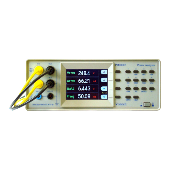
PM1000+
P
A
OWER
NALYZER
U
M
SER
ANUAL
Need help?
Thank you for choosing to use this Voltech Power Analyzer. It has
been designed to be safe and easy to use.
Should you experience any difficulty during the set up or use of any
Voltech product, or are unsure of any of their features or abilities,
please do not hesitate to contact either your local supplier or visit
our applications support center at www.voltech.com.
Voltech Instruments Inc.
Voltech Instruments Ltd.
11637 Kelly road, Suite 306
148 Harwell Business Centre
Fort Myers, FL33908
Didcot, Oxon, OX11 0RA
U.S.A.
U.K.
Tel: 239 437 0494
Tel: +44 1235 834555
Fax: 239 437 3841
Fax: +44 1235 835016
sales@voltech.com
sales@voltech.co.uk
PM1000+ Power Analyzer User Manual
© Voltech 2010
Page
I
Advertisement
Table of Contents

Subscribe to Our Youtube Channel
Related Manuals for Voltech PM1000+


Summary of Contents for Voltech PM1000+
- Page 1 NALYZER ANUAL Need help? Thank you for choosing to use this Voltech Power Analyzer. It has been designed to be safe and easy to use. Should you experience any difficulty during the set up or use of any Voltech product, or are unsure of any of their features or abilities, please do not hesitate to contact either your local supplier or visit our applications support center at www.voltech.com.
- Page 2 Voltech Instruments is committed to a policy of continuous product development. Hence product specification and the information given in this manual are subject to change without notice. No part of this publication may be reproduced, stored in a retrieval system, or transmitted in any form, or by means electronic, mechanical photocopying, recording or otherwise, without prior written permission of Voltech Instruments.
- Page 3 Solo personale qualificato può installare questo strumento, dopo la lettura e la comprensione di questo manuale. Se esistono dubbi consultate il vostro rivenditore. IMPORTANT: Please consult the safety information section of this user manual before installation and use. PM1000+ Power Analyzer User Manual © Voltech 2010 Page III...
- Page 4 Page IV © Voltech 2010 PM1000+ Power Analyzer User Manual...
-
Page 5: Table Of Contents
3.4. To connect a transducer with a voltage output ..........24 3.5. To connect a Voltage Transformer / Transducer ..........25 Voltage Scaling....................25 4. The Menu System ..................26 4.1. Navigation ......................26 4.2. Menu Items .......................26 4.3. Main Menu ......................26 PM1000+ Power Analyzer User Manual © Voltech 2010 Page V... - Page 6 Harmonics Setup .....................35 Distortion Setup ....................35 Auto Zero ......................36 Clock Setup .....................36 Unit Configuration ....................36 IEC Key Code Entry ..................36 4.10. User Configuration..................36 4.11. View........................37 Zoom .......................37 Contrast ......................37 Page VI © Voltech 2010 PM1000+ Power Analyzer User Manual...
- Page 7 Reporting Results ....................66 6.2. IEC 62301 Low Power Standby Software ............68 6.3. PM1000+ General Purpose Measurement Software .........68 7. Specification ....................70 7.1. Mechanical ......................70 Accessories .....................70 7.2. Power Supply ....................70 PM1000+ Power Analyzer User Manual © Voltech 2010 Page VII...
- Page 8 8.3. Obtaining Service and Applications Support .............82 8.4. Updating Firmware ....................82 9. Safety Information ..................83 9.1. Safety Features ....................83 9.2. Safety Instructions ....................83 9.3. Declaration of Conformity ..................85 10. Release History ..................87 Page VIII © Voltech 2010 PM1000+ Power Analyzer User Manual...
-
Page 9: Introduction
EATURES BILITIES The Voltech PM1000+ is a powerful and versatile precision power analyzer. Designed to provide clear and accurate measurements of electrical power and energy on all electrical products, the PM1000+ is both an easy to use bench instrument and a fast and programmable automatic test interface. -
Page 10: Package Contents
1.2. ACKAGE ONTENTS The following items are supplied with your PM1000+. Please check that you have every item and report any missing items to your Voltech supplier as soon as possible PM1000+ Power Analyzer Certificate of Conformance and Calibration CD including user‟s manual and calibration data... -
Page 11: Quick Start
The PM1000+ will start its power up sequence. This takes 5-10 seconds. During power up you will see the PM1000+‟s serial number and last adjustment date. 5. The instrument is now ready for use PM1000+ Power Analyzer User Manual © Voltech 2010 Page... -
Page 12: Connecting To The Product Under Test
Always use good quality safety cables as supplied and check that they are not damaged before use. V HI V LO To ac To load supply live neutral A HI To load neutral A LO To supply neutral Page 12 © Voltech 2010 PM1000+ Power Analyzer User Manual... -
Page 13: Default Measurements
TART The simplest and safest way to make a connection to the product under test is to use a Voltech Break Out Box. This provides a line socket for connection of the product and 4 x 4mm sockets for direct connection to the PM1000+ terminals as described above. -
Page 14: Navigating The Menu System
To return to the measurement display at any time, simply press the MENU key again. With the menu system active, the 4 soft keys to the right of the display may be used to navigate and select options. MENU KEYS Page 14 © Voltech 2010 PM1000+ Power Analyzer User Manual... -
Page 15: Menu Keys
4. (Option). Move the measurement 5. Press OK. To remove a measurement, select it and press Hint: To restore the default list, see the User Configuration Menu. PM1000+ Power Analyzer User Manual © Voltech 2010 Page 15... -
Page 16: Key Shortcuts
Printers Tested w/ the PM1000+ To send results to a printer, press the "VWX" key on the front panel. All the currently selected results will be printed to the currently selected printer. Page 16 © Voltech 2010 PM1000+ Power Analyzer User Manual... -
Page 17: Data Logging
PM1000+ screen. The basic format of the data is shown below. Time and date will be in 24hr and year, month, day (YYYYMMDD) format respectively. PM1000+ Power Analyzer User Manual © Voltech 2010 Page 17... -
Page 18: Unit Configuration
UICK TART Voltech Instruments PM1000+ Serial Number: 100008200001 Firmware Version 4.13RC4 Start Date (YYYYMMDD): 10/30/2008 Start Time (24hr): 8:00:33 Index Vrms Arms Watt Freq 2.09E-01 2.90E-03 1.83E-04 0 3.02E-01 2.08E-01 2.90E-03 1.83E-04 0 3.03E-01 2.08E-01 2.91E-03 1.82E-04 0 3.01E-01 2.08E-01 2.90E-03... - Page 19 Full adjustment to specifications (see Section 7.5). Full Enhanced Full adjustment to enhanced specification (see Section 7.5). To receive a Full Enhanced adjustment the unit must be sent back to Voltech Instruments. PM1000+ Power Analyzer User Manual © Voltech 2010...
-
Page 20: Using Voltage And Current Transducers
Whether there is DC current present. Convenience of connection – E.g. using a clamp-on current transformer, with jaws that open, for quick connection in a fixed wiring loom. The effect of the transducer on the circuit. PM1000+ Power Analyzer User Manual © Voltech 2010 Page... -
Page 21: To Connect A Simple Current Transfomer
IMPLE URRENT TRANSFOMER To use a conventional current transformer (CT) like the Voltech CL series (or any other transducer with a current output), connect the normal AHI and ALO inputs of the PM1000+ to the outputs of the current transformer. Follow the manufacturer‟s instructions for the safe use and installation of the transducer. -
Page 22: To Connect An External Resistive Shunt
This is well within the 1V rating of the PM1000+‟s External Current Inputs 2. Connect the shunt in series with the load and to the EXT-HI and EXT-LO inputs as shown. Page 22 © Voltech 2010 PM1000+ Power Analyzer User Manual... - Page 23 To enter a scale factor for current: Press ‟MENU‟ „Inputs‟ and press Select „Scaling‟ and press Select „Amps‟ and press Select Use the delete key to clear the entry. PM1000+ Power Analyzer User Manual © Voltech 2010 Page 23...
-
Page 24: To Connect A Transducer With A Voltage Output
Scale = 1 / 10 = 0.1 Press ‟MENU‟ „Inputs‟ and press Select „Scaling‟ and press Select „Amps‟ and press Select Use the delete key to clear the entry. Page 24 © Voltech 2010 PM1000+ Power Analyzer User Manual... -
Page 25: To Connect A Voltage Transformer / Transducer
Type the new scale factor (100) Press Press „MENU‟ to return to the measurement display. The PM1000+ is now ready to make measurements using a VT. PM1000+ Power Analyzer User Manual © Voltech 2010 Page 25... -
Page 26: The Menu System
To remove a measurement, select it and press Hint: To restore the default list, see the User Configuration Menu. For information on setup for harmonics and distortion factor, see section 4.10 System Configuration. PM1000+ Power Analyzer User Manual © Voltech 2010 Page... -
Page 27: Modes
IEC Current Harmonics – This mode is control via PC software. It enables pre- compliant current harmonic measurements to IEC 61000-3-2 to be made. This mode is optional on the PM1000+. Please visit www.voltech.com for more information. IEC Voltage Flicker – This mode is control via PC software. It enables pre- compliant Pst measurements to be made as described in IEC 61000-3-3. - Page 28 A range = Measurement available * = Displayed as default Also, depending on which mode you change to, other settings may be changed. The changes are listed below: Page 28 © Voltech 2010 PM1000+ Power Analyzer User Manual...
-
Page 29: Setup Mode
In the Clock Start Method the PM1000+ will use its real time clock to start the integrator based on the date and time set up by the user. The user will also PM1000+ Power Analyzer User Manual © Voltech 2010 Page 29... -
Page 30: Inputs
Select Volts or Amps and press to choose the range. Changing the measurement mode (4.5) will often reset the voltage and current range to auto. Page 30 © Voltech 2010 PM1000+ Power Analyzer User Manual... -
Page 31: Scaling
PM1000+ for use with current transducers that provide a voltage output. Because the 0V is common to both the internal and external shunts, only one type may be connected at any time. PM1000+ Power Analyzer User Manual © Voltech 2010 Page 31... -
Page 32: Blanking
NOTE: Waveforms will only be displayed when there is a valid frequency. DC waveforms will not be displayed. Harmonic Bar Chart Select Voltage or Current harmonic bar chart using the keys and press details. Page 32 © Voltech 2010 PM1000+ Power Analyzer User Manual... -
Page 33: Integration Graph
The PM1000+ uses hardware handshaking (RTS / CTS) with no parity, 8 data bits and 1stop bit (N,8,1). The RS232 baud rate is unchanged after a “*RST” or “:DVC” command. PM1000+ Power Analyzer User Manual © Voltech 2010 Page 33... -
Page 34: Gpib Address
To configure the static IP address, choose “Static IP Settings” in the Ethernet Setup menu. This allows entry of the IP address, the subnet mask and the default gateway. After entering the relevant data press the button, in each menu, to apply. Page 34 © Voltech 2010 PM1000+ Power Analyzer User Manual... -
Page 35: System Configuration
DC (H0): Include or exclude DC in the series formula. (default = exclude) Reference: rms or 1st harmonic. (default = rms) See section 6.4 for details of the actual equations used. PM1000+ Power Analyzer User Manual © Voltech 2010 Page 35... -
Page 36: Auto Zero
The first option is to „Load Default‟. Choosing this option will set every menu option of the PM1000+ to its factory default. The other menu items (Default „CONFIGURATION n‟) may be used to store and recall all settings of the PM1000+ Page 36 © Voltech 2010 PM1000+ Power Analyzer User Manual... -
Page 37: View
Zoom Select either 4 results or 14 results display and press to confirm. Contrast Enter a contrast number and press to confirm. 50 is the default value. PM1000+ Power Analyzer User Manual © Voltech 2010 Page 37... -
Page 38: Remote Operation
Returns the Status Byte Register (STB) as a decimal value. “:AVG <value>” Enable or disable averaging of results (averaging depth of 4). <value> = 0 → Disable (default) <value> = 1 → Enable PM1000+ Power Analyzer User Manual © Voltech 2010 Page... - Page 39 Returns the IP address currently in use. “:COM:ETH:SUB?” Returns Subnet Mask currently in use. “:COM:ETH:MAC <value>” Will set the MAC address. Accepts the lower 24 bits as ASCII hex string. Ex. <value> = 5AB2F1. PM1000+ Power Analyzer User Manual © Voltech 2010 Page 39...
- Page 40 Returns the current selection list ":FSR:VLT” Sets the frequency source for voltage ":FSR:AMP” Sets the frequency source for current ":FSR?” Returns the freq source 0 = volts 1 = amps Page 40 © Voltech 2010 PM1000+ Power Analyzer User Manual...
- Page 41 <value> = 1 → difference ":HMX:THD:SEQ <value>" Select the THD sequence: <value> = 0 → All <value> = 1 → odd only ":HMX:THD:RNG <value>" Set the THD range <value> = 2 to 50. PM1000+ Power Analyzer User Manual © Voltech 2010 Page 41...
- Page 42 Clock Start Method. Start time sent in current PM1000+ time format. xx-xx-xxX stands for hh-mm-ss (uppercase „X‟ is not used) for 24hr time format or hh-mm-ss(A or P) for AM/PM time format. Page 42 © Voltech 2010 PM1000+ Power Analyzer User Manual...
- Page 43 Manual Start Method. (1.0 ≤ <value> ≤ 1,000,000) ":MOD:NOR” Sets normal mode. ":MOD:INR” Sets inrush mode. “:MOD:INT” Sets integrator mode. ":MOD:SBY” Sets standby power mode. PM1000+ Power Analyzer User Manual © Voltech 2010 Page 43...
- Page 44 Returns the current voltage range. ":RNG:AMP?” Returns the current amps range. ":RNG:VLT:AUT?” 0 → Range fixed. Returns : 1 → AutoRange engaged. ":RNG:AMP:AUT?” 0 → Range fixed. Returns : 1 → AutoRange engaged. Page 44 © Voltech 2010 PM1000+ Power Analyzer User Manual...
- Page 45 Selects watt hrs. ":SEL:VAH” Selects VA hrs. ":SEL:VRH” Selects VAr hrs. ":SEL:AHR” Selects A hrs. ":SEL:VDF” Selects Vdf. ":SEL:ADF” Selects Adf. ":SEL:FRQ” Selects frequency. ":SEL:RES” Selects resistance R. ":SEL:IMP” Selects impedance Z. PM1000+ Power Analyzer User Manual © Voltech 2010 Page 45...
-
Page 46: Sending And Receiving Commands
1 = ddmmyyyy; 2 = yyyymmdd ":SYST:ZERO <value>” Set auto zero: <value> = 0 → disabled <value> = 1 → enabled ":SYST:ZERO?” Read auto zero state. 5.3. ENDING AND ECEIVING OMMANDS Page 46 © Voltech 2010 PM1000+ Power Analyzer User Manual... -
Page 47: Communications Examples
:SEL:CLR clears all results :SEL:VLT :SEL:AMP :SEL:FRQ :SEL:WAT :SEL:VAS :SEL:VAR :SEL:PWF :SEL:VPK+ PM1000+ Power Analyzer User Manual © Voltech 2010 Page 47... -
Page 48: Returning Results Repeatedly
:HMX:VLT:SEQ 0 Select odd and even harmonics (use 1 to select odd harmonics only) :HMX:VLT:RNG 9 Return all harmonic from 1 to 9. Page 48 © Voltech 2010 PM1000+ Power Analyzer User Manual... -
Page 49: Standby Power
Wait 60 seconds :FRD? Read back values including average power over 60 seconds Wait 60 seconds :FRD? Read back value including average power over 60 seconds. Check against previous power. PM1000+ Power Analyzer User Manual © Voltech 2010 Page 49... -
Page 50: Inrush
Selects peak positive current :SEL:APK- Selects peak negative current Ensure equipment under test is off :MOD:INR:CLR Clear the Apk+ and Apk- Switch on equipment under test :FRD? Returns Apk+ and Apk-. Page 50 © Voltech 2010 PM1000+ Power Analyzer User Manual... -
Page 51: Status Reporting
If any of the status registers are read, that register is reset to zero. IEC_ IEC_ IEC_ :DSR? data status Flick Flick data enable IEC_ IEC_ IEC_ :DSE Flick Flick :DSE? standard *ESR? event status *ESE standard *ESE? event enable status byte *STB? PM1000+ Power Analyzer User Manual © Voltech 2010 Page 51... -
Page 52: Status Byte Register (Stb)
Bit 1 - NDV Set to indicate that new data has become available since the last :DSR? command. Cleared when read. Bit 0 - DVL Set to indicate the availability of data. Cleared when read. Page 52 © Voltech 2010 PM1000+ Power Analyzer User Manual... -
Page 53: Display Data Status Enable Register (Dse)
Standard Event Status Enable Register (ESE) Read by “*ESE?” and set by “*ESE <value>”. Cleared when read. Bit 5 - CME Enable CME bit in ESR. (Default to enabled on power-up.) PM1000+ Power Analyzer User Manual © Voltech 2010 Page 53... - Page 54 EMOTE PERATION Page 54 © Voltech 2010 PM1000+ Power Analyzer User Manual...
-
Page 55: Software
PM1000+ will allow 10 current harmonic or flicker tests to be run before purchase is required. Please contact your Voltech agent to purchase the feature. Where to find it The software can be found on Voltech‟s web site at www.voltech.com in the software and firmware section. Software Installation Double click on the file “PM1000IEC6000.exe”... -
Page 56: Hardware Setup
For the measurement of voltage and current in normal appliances that plug in to the wall output, Voltech has a Universal Breakout Box. A connection diagram for the PM1000+ and the breakout box is shown below: Universal Breakout Box The UUT is connected to the “OUTPUT TO –... -
Page 57: Running The Fluctuating Harmonics Test
After the software starts up, you should see a message in the bottom left of the main window that states that a PM1000+ has been detected. An example for USB connection is shown below: PM1000+ Power Analyzer User Manual © Voltech 2010 Page 57... - Page 58 220 V (line-to- neutral). The software will give a warning for settings that will cause non-compliance with the IEC 61000-3-2 standard. Page 58 © Voltech 2010 PM1000+ Power Analyzer User Manual...
- Page 59 This section allows the user to enter information about the test that will be run. For the purposes of this test it can be filled out as seen below: Part Name and Test Description Input PM1000+ Power Analyzer User Manual © Voltech 2010 Page 59...
- Page 60 OFTWARE Class This section determines the class of the UUT. Please refer to Voltech Application Note 104 for information on determining the class of the UUT. Class Selection Normal or Inter-harmonics Select normal if you would like to test without inter-harmonics or select Inter-harmonics to test with inter-harmonics.
- Page 61 Start the Fluctuating Harmonics Test From the top-level menu, select Run Test → Run Fluctuating Harmonic Test. You will see a window pop up with a “Start Harm/Source Test” button; click on that button. PM1000+ Power Analyzer User Manual © Voltech 2010 Page 61...
- Page 62 The test should start after the ten second wait required by the standard. While the test runs you will see a display of the current harmonic levels and a countdown timer of the test duration as shown below: Page 62 © Voltech 2010 PM1000+ Power Analyzer User Manual...
- Page 63 Report. To view other results, click on Results → Open Harmonic Files from the top- level menu. This will open up a window that allows you to select the results you would like to see. PM1000+ Power Analyzer User Manual © Voltech 2010 Page 63...
-
Page 64: Running The Flicker Test
This area allows you to specify the complex impedance in ohms of the line being tested. Program defaults to 0.4 ohms real and 0.25 ohms imaginary as per IEC standard 61000-3-3. Page 64 © Voltech 2010 PM1000+ Power Analyzer User Manual... - Page 65 From the top-level menu, select Run Test → Run Flicker Test. You will see a window pop up informing you to have the UUT powered and to allow a warm-up period of at least 30 minutes. Click “OK.” Flicker Test Window PM1000+ Power Analyzer User Manual © Voltech 2010 Page 65...
-
Page 66: Reporting Results
Open Harmonic Results On the left, select the set of results desired. Then on the right, select the reports that you desire to view. Page 66 © Voltech 2010 PM1000+ Power Analyzer User Manual... - Page 67 To open a flicker result, select the test you would like from the list and click “Open Results.” Further Information Also, for information in IEC 61000-3 testing in general, visit the Harmonics and Flicker section of Voltech‟s Solutions at www.voltech.com. PM1000+ Power Analyzer User Manual © Voltech 2010 Page 67...
-
Page 68: Iec 62301 Low Power Standby Software
Further Information To run the software click on Start -> Program Files -> Voltech Software -> IEC 62301 Software or click on the “IEC 62301 Software” icon on the desktop. When the software runs, you will be asked whether you want to run a setup wizard. - Page 69 Further Information To run the software click on Start -> Program Files -> Voltech Software -> PM1000+ Software or click on the “PM1000+ Software” icon on the desktop. When the software runs for the first time, you will be asked to choose a language.
-
Page 70: Specification
358mm with Handle Straight out Weight = 3.2Kg with handle Accessories Voltech supplies the PM1000+ Rack Mount Shelf Fixing kit (VPN: 130-024) to mount the PM1000+ in a 19” wide cabinet. A suitable shelf is recommended. Call your Voltech representative for more information. -
Page 71: Aux/Trig
6 - Open 7 - CTS (i/p) 8 - RTS (o/p) 9 - Open AUX/TRIG For Voltech Use Only. GPIB To IEEE488 standard. USB Peripheral (USB Test and Measurement Class [USBTMC]) USB 2.0 compatible. Will work with any USB 2.0 system. -
Page 72: Measured Parameters
Amps Apparent (VA) Power Volt- Reactive Amps Power Reactive (VAr) Voltage Peak Value Value Crest Factor Current Peak Value Value Crest Factor ..series Voltage Total Harmonic Vrms difference Distortion Page 72 © Voltech 2010 PM1000+ Power Analyzer User Manual... - Page 73 Volt (V) harmonic n Phase Current Amp (A) harmonic n Phase (+)ve Peak Voltage Volt (V) (-)ve Peak Volt (V) Voltage (+)ve Peak Amp (A) Current (-)ve Peak Amp (A) Current PM1000+ Power Analyzer User Manual © Voltech 2010 Page 73...
-
Page 74: Measurement Accuracy
0.5% of Reading + 0.5% of Range + (0.02 * F)% of reading Effects of Common 100Vrms, 100kHz <500mV Mode Voltage MAX VOLTAGE Peak continuous 1500Vpk OVERANGE Peak < 1 second 5000Vpk Page 74 © Voltech 2010 PM1000+ Power Analyzer User Manual... - Page 75 0.2% of Reading + 0.4% of range +4mW RANGES 1 VA to 90kVA Frequency range 10Hz to 1MHz Accuracy 0.2% Reading + 0.1 % of range +4mVA + (0.05 * F)% of reading PM1000+ Power Analyzer User Manual © Voltech 2010 Page 75...
- Page 76 Accuracy %Vpk error + %Vrms error CURRENT CREST RANGE 1.00 to 20.0 FACTOR Accuracy %Apk error + %Arms error PEAK INRUSH RANGE 100Apk CURRENT Accuracy 2% of range +/- 20mA Page 76 © Voltech 2010 PM1000+ Power Analyzer User Manual...
- Page 77 0.005Ohms to 1Mohm Accuracy 0.2% of Reading + 0.1% of range +5mOhms +((0.05 / (1- PF)) * F)% of reading EXTERNAL SHUNT Input Range +/- 1250 mVpk SCALING 0.0001 to 100000 PM1000+ Power Analyzer User Manual © Voltech 2010 Page 77...
- Page 78 7. Specifications are valid only when applicable voltage and current inputs are > 10% of range. The exception is harmonics where the specification is valid when the magnitude of the harmonic is >2% of range. Page 78 © Voltech 2010 PM1000+ Power Analyzer User Manual...
-
Page 79: Example Of Volts, Amps And Watts Accuracy Calculations
= 0.1% of 2.5A + 0.1% of 6.25A + 1mA + (0.02 * 0.06)% of 2.5A = 2.5mA + 6.25mA + 1mA + 0.03mA = 9.78mA or 0.39% of signal. PM1000+ Power Analyzer User Manual © Voltech 2010 Page 79... - Page 80 Accuracy = 0.2% of 240W + 0.1% of 1343.75W + 4mW + (0.05 / 0.8 * 0.06)% of 240W = 480mW + 1343.75mW + 4mW + 9mW = 1.837W or 0.77% of signal. Page 80 © Voltech 2010 PM1000+ Power Analyzer User Manual...
-
Page 81: Warranty, Service And Updates
Shipment from the customer address will be the responsibility of the customer. Voltech reserves the right to waive this benefit in any event where it is clear upon inspection that the cause of the failure is due to customer misuse. -
Page 82: Obtaining Service And Applications Support
ERVICE AND PDATES For details of calibration facilities and any other service requests, please see the service area of our website at www.voltech.com. Voltech strongly recommends that you discuss your service requirements with your supplier before service is needed. 8.3. -
Page 83: Safety Information
If the PM1000+ is used in a manner not specified by Voltech Instruments, Inc., the protection provided by the equipment may be impaired. - Page 84 Replace fuses only with the same type and rating as specified in this manual. This instrument must be properly rack mounted or must have either two feet and the handle or all four feet making contact on a flat, firm, horizontal surface. Page 84 © Voltech 2010 PM1000+ Power Analyzer User Manual...
-
Page 85: Declaration Of Conformity
Supplementary Information: The product herewith complies with the requirements of the EMC Directive 2004/106/EC for EMC and the Low Voltage Directive 2006/95/EC. Signed for on behalf of Voltech Instruments Ltd February 2009 PM1000+ Power Analyzer User Manual © Voltech 2010... -
Page 87: Release History
Version 7 to Version 8 (version 4.20 firmware). Section 4.5 (Modes) updated to include information IEC current harmonics and IEC voltage flicker modes. Changes made the System Configuration section (4.9) in reference to the enabling of IEC mode. PM1000+ Power Analyzer User Manual © Voltech 2010 Page... - Page 88 Added specification for current channel common mode rejection in section 7.5. Add notes to the description of Standby mode in section 4.5. Version 10 to Version 11 (Version 4.22 firmware). Added an improved specification for 45-65Hz, Volts, Amps and Watts. Page 88 © Voltech 2010 PM1000+ Power Analyzer User Manual...
Need help?
Do you have a question about the PM1000+ and is the answer not in the manual?
Questions and answers