
Subscribe to Our Youtube Channel
Related Manuals for atecpool ATHP50


Summary of Contents for atecpool ATHP50
- Page 1 HiHeat Hot Water Heat Pump HIGH TEMPERATURE UNITS Installation & Instruction Manual ATHP50 & ATHP70...
-
Page 3: Table Of Contents
CONTENT 1. Preface 2. Overall Information of the Heat Pump 2.1 Device description 2.2 Features of the high temperature heat pump 2.3 Specification data 2.4 Heat pump dimension and view 3. Installation and Maintenance 3.1 Cautions and warning 3.2 Transit 3.3 Installation occasions 3.4 Installation method 3.5 Water loop connection... -
Page 4: Preface
Preface Welcome to air source water heat pump. Your decision to purchase heat pump will reward you for many years.This is your assurance that you have purchased quality heat pump system available, one that is manufactured in a state-of-the-art facility and goes with innovation. -
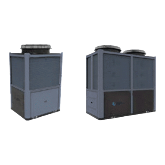
Page 5: Overall Information Of The Heat Pump
Overall Information of the Heat Pump 2.1 Device description The air source heat pump extracts heat from ambient air and transfers itto water. By circulating the water, the energy is used to warm the house efficiently. Through the usage of floor heating, the heat pump COP can be as high as 4.5. In reverse, cooling is also available when it is needed. -
Page 6: Specification Data
Overall information of the Heat Pump 2.3 Specification data Unit Model ATHP50 ATHP70 Rated heating capacity 70.0 35.0 Rated hot water capacity 1.204 0.752 m /h Rated heating power input Rated heating current input 37.49 18.3 3.68 3.68 Power supply 380-415V/3N~/50Hz... -
Page 7: Heat Pump Dimension And View
Overall information of the heat pump 2.4 Heat pump dimension and view Unit Models ATHP70 G2" Water Outlet G2" Water Inlet Drainage G1/2" 1938 Unit Models ATHP50 G1.5” Water Outlet Drainage G1/2” 1200 G1.5” Water Inlet... -
Page 8: Installation And Maintenance
Installation and Maintenance 3.1 Cautions and Warning To prevent the users and others from the harm of this unit, and avoid damage on the unit or other property, and use the heat pump properly, please read this manual carefully and understand the following information correctly. - Page 9 Installation and Maintenance Warning Installation Meaning The heat pump must be installed by qualified personals, to avoid improper installation which can lead to water Professional installer leakage, electrical shock or fire. is required. Please make sure that the unit and power connection have good earthing, otherwise may cause electrical Earthing is required shock.
- Page 10 Installation and Maintenance Attention Installation Meaning The unit CANNOT be installed near the flammable gas. Once there is any leakage of the gas, fire can be occur. Installation Place Make sure that the basement of the heat pump is strong enough, to avoid any decline or fall down of the unit Fix the unit Make sure that there is circuit breaker for the unit, lack of...
-
Page 11: Transit
Installation and Maintenance 3.2 Transit When the heat pump is transported please keep the unit stand up. The unit cannot be laid down, otherwise the inner parts of the device may be damaged. When the unit need to be hung up during installation, a 8 meters cable is needed, and there must be soft material between the cable and the unit to prevent damage to the heat pump cabinet. -
Page 12: Water Loop Connection
Installation and Maintenance 3.5 Water loop connection Please pay attention to below matters when the water pipe is connected: Try to reduce the resistance to the water from the piping. The piping must be clear and free from dirty and blocks. Water leakage test must be carried out to ensure there is no water leaking. -
Page 13: Power Supply Connection
When all the wiring is completed, the power can only be connected after a double check. Power Specifications Creepage Items Cable Power Supply Unit Model Protector 30mA Less 380V/3N~/50Hz 2*10mm 3*6mm ATHP50 Than 0.1 30mA Less 2*10mm 380V/3N~/50Hz 3*10mm Than 0.1 ATHP70... -
Page 14: Trial Running
Installation and Maintenance 3.9 Trial running Inspection before trial running Check the indoor unit, and make sure that the pipe connection is right and the relevant valves are open . Check the water loop, to ensure that the water inside of the expansion tank is enough, the water supply is good, the water loop is full of water and without any air. -
Page 15: Maintenance
Installation and Maintenance 3.10 Maintenance Check the water supply and air vent frequently, to avoid lack of water or air in the water loop. Clean the water filter in a certain period to keep good water quality. Lack of water and dirty water can damage the unit. -
Page 16: Controlling And Operation
Controlling and Operation 4.1.Main interface display and function (1) Electricity Interface Fig.1 Electricity interface (2) Main interface of power-off interface Fig.2 Power-off interface... - Page 17 Controlling and Operation (3) Main interface of power-on 11 12 14 15 ⑩ ① ④ ② ⑤ ③ ⑥ ⑦ ⑧ ⑨ Fig.3 Power-on interace Button function Name Function Press to switch Control 4 units with communication Power ① to fully open and close Press to set the target temperature Setpoint ②...
-
Page 18: Instructions For Operation Of Wire Controller
Controlling and Operation Running status icons description Description Icon Set target return water temperature ⑦ Indicating the operating status: Display circle ⑧ red-heating mode; grey-power-off mode. Set target water tank temperature ⑨ Indicating the date and time ⑩ Indicating the Temp Timer function is activated Indicating that the electric auxiliary heating mode is activated Indicating that the power timer mode is activated Indicating the lock screen status... - Page 19 Controlling and Operation (5) Timer setting Fig. 4 Timer interface Button function Name Function Power Timer Press to jump to the timing switch setting interface Return Water Press to jump to the return valve timing setting interface Valve Timer Press to jump to the time-sharing temperature control setting Temp Timer interface Power Timer...
- Page 20 Controlling and Operation Power Timer function allows you to set the opening time of the unit for each day of Power Timer function allows you to set the opening time of the unit for each day of the week, while this function is enable, the main interface displays “ the week, while this function is enable, the main interface displays “...
- Page 21 Controlling and Operation (6) Setting function Page left Fig. 7-1 Setting interface Page right Fig. 7-2 Setting interface...
- Page 22 Controlling and Operation Button function Name Function Parameter Press and enter password “22” to inquire installer parameter Failure Press to inquire failure record Press to jump to the Time Setting interface and adjust Time system time parameter Electric Heating Press to turn on/off the electric heating mode Temp Curve Press to inquire the temperature curve Setting interface...
- Page 23 Controlling and Operation Electric Heating function In the Setting interface (Fig.7), while the botton displays “OFF Electric Heat- ing”, firstly make sure the unit is operated in heating mode, then press Electric Heating button to jump to Electric Heating interface (Fig.9), click the button to be ON, the electric auxiliary heating mode is activated;...
-
Page 24: Electronic Control Failure Code And Troubleshooting Table
Controlling and Operation 4.3 Electronic control failure code and troubleshooting table Failure code and troubleshooting table Protection/failure Codes Causes Removal methods Inspect whether the wire controller, the main Abnormal communication between wire Communication Fault board and the connection thereof are reliable controller and the main board Check the wire control software number and the The wire contrware isnot match the... - Page 25 Controlling and Operation Protection/fault Codes Causes Removal methods Inspect whether the electric heating is under Electric heating overheat protection switch is Electric Heater Overheating 3+ operation condition of over 150℃ for a long time disconnected Inspect whether the water flow of the water pipe Syst 1: Antifreezing Prot.
-
Page 26: Interface Diagram
Controlling and Operation Protection/fault Codes Causes Removal methods E101 System 1 compressor running current is too large Check if the current is too high Syst 1: Comp. Overcurrent Prot. E201 System 2 compressor running current is too large Check if the current is too high Syst 2: Comp. - Page 27 Controlling and Operation (2) Expansion board interface diagram AI 10(50K) KZ10 AI 9(50K) (3) Expansion board interface description Sign Meaning Sign Meaning AI/DI01 Syst 2: Coil Temp. 0-5V_IN3 Syst1: High Pressure AI/DI02 Syst 2: Suction Temp 0-5V_IN4 Syst2: High Pressure AI/DI03 Syst 2: Antifreezing Temp 5V output...
- Page 28 Controlling and Operation (4) Motherboard interface diagram P C 4 0 0 3 (5) Expansion board interface description Sign Meaning Sign Meaning PWM_OUT1 AI/DI01 Inlet Temp No use PWM_OUT2 AI/DI02 Outlet Temp No use 0-10V_OUT1 AI/DI03 Syst 1: Coil Temp No use 0-10V_OUT2 AI/DI04...
-
Page 29: Appendix
Appendix 7.1Caution & Warning 7.1.1The unit can only be repaired by qualified installer centre personnel or an authorised dealer. for Europe market 8. 7.1.2 This appliance is not intended for use by persons (including children) with reduced physical sensory or mental capabilities, or lack of experience and knowledge, unless they have been given supervision or instruction concerning use of the appliance by a person responsible for their safety. -
Page 30: Cable Specification
Appendix 7.2 Cables specification 7.2.1 Single phase unit Nameplate Creepage protector Signal line maximum Phase line Earth line current No more 2 1.5mm 1.5mm 30mA less than 0.1 sec than 10A 2 2.5mm 2.5mm 30mA less than 0.1 sec 10~16A 2 4mm 30mA less than 0.1 sec 16 ~25A... - Page 32 Code:20210913-0006...
Need help?
Do you have a question about the ATHP50 and is the answer not in the manual?
Questions and answers