Sign In
Upload
Download
Table of Contents
Contents
Add to my manuals
Delete from my manuals
Share
URL of this page:
HTML Link:
Bookmark this page
Add
Manual will be automatically added to "My Manuals"
Print this page
×
Bookmark added
×
Added to my manuals
Manuals
Brands
AudioCodes Manuals
Gateway
MediaPack 504
Hardware installation manual
AudioCodes MediaPack 504 Hardware Installation Manual
Analog voice gateway
Hide thumbs
1
Table Of Contents
2
3
4
5
6
7
8
9
10
11
12
13
14
15
16
17
18
19
20
page
of
20
Go
/
20
Contents
Table of Contents
Bookmarks
Table of Contents
Table of Contents
Notice
WEEE EU Directive
Customer Support
Stay in the Loop with Audiocodes
Abbreviations and Terminology
General Notes and Warnings
Safety Precautions
Related Documentation
Documentation Feedback
Introduction
Unpacking the Device
Physical Description
Physical Dimensions and Operating Environment
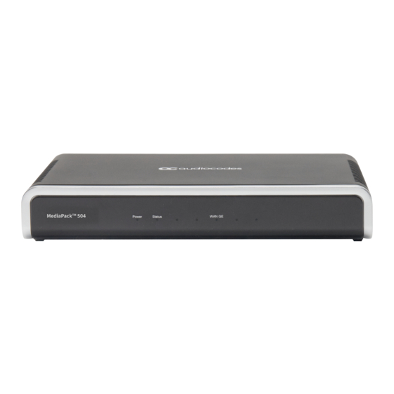
Front Panel Description
Rear Panel Description
Mounting the Device
Desktop Mounting
19-Inch Rack Mounting
Wall Mounting
Cabling the Device
Cabling WAN Interface
Cabling FXS Analog Interfaces
Connecting to Power
Advertisement
Quick Links
1
Table of Contents
2
Rear Panel Description
3
Cabling the Device
4
Cabling Wan Interface
5
Cabling Fxs Analog Interfaces
Download this manual
MediaPack 50 4-5 08 (M P-5xx) Hardware Installation Ma nual
Hardware Installation Manual
AudioCodes MediaPack™ 5xx Analog Voice Gateway Series
MediaPack 504 (MP-504)
MediaPack 508 (MP-508)
Table of
Contents
Previous
Page
Next
Page
1
2
3
4
5
Advertisement
Table of Contents
Need help?
Do you have a question about the MediaPack 504 and is the answer not in the manual?
Ask a question
Questions and answers
Related Manuals for AudioCodes MediaPack 504
Gateway AudioCodes MediaPack 5 Series Hardware Installation Manual
Analog voice gateway (33 pages)
Gateway AudioCodes Mediant 500L User Manual
Enterprise session border controller (e-sbc) & media gateway (1260 pages)
Gateway AudioCodes Mediant 500L Hardware Installation Manual
Mediant series enterprise session border controller (e-sbc) and media gateway (38 pages)
Gateway AudioCodes Mediant Series Quick Setup Manual
Bri/pri gateway (48 pages)
Gateway AudioCodes Mediant 500L Quick Setup Manual
Enterprise session border controller (9 pages)
Gateway AudioCodes M500L Hardware Installation Manual
Enterprise session border controller and media gateway (38 pages)
Gateway AudioCodes Mediant 500 Quick Setup Manual
And e-sbc (9 pages)
Gateway AudioCodes Gateway & Session Border Controller Series Hardware Installation Manual
(24 pages)
Gateway AudioCodes Mediant 500 Quick Manual
Connecting pbx to broadsoft sip trunk using audiocodes mediant pri gateway (40 pages)
Gateway AudioCodes Mediant Series Configuration Note
Mediant series voip media gateways for microsoft office 365, exchange online unified messaging with legacy pbx (46 pages)
Gateway AudioCodes Mediant 500 E-SBC User Manual
Enterprise session border controller digital voip media gateway (920 pages)
Gateway AudioCodes Mediant 500Li Quick Setup Manual
Analog voip gateway (10 pages)
Gateway AudioCodes i Series Hardware Installation Manual
Audiocodes mediant integrated voice & data routers (48 pages)
Gateway AudioCodes Mediant 500Li Quick Setup Manual
Analog voip gateway (10 pages)
Gateway AudioCodes MediaPack 508 Hardware Installation Manual
Analog voice gateway (20 pages)
Gateway AudioCodes MediaPack 524 Hardware Installation Manual
Analog voice gateway (33 pages)
This manual is also suitable for:
Mediapack 508
Mp-504
Mp-508
Mediapack 5 series
Table of Contents
Print
Rename the bookmark
Delete bookmark?
Delete from my manuals?
Login
Sign In
OR
Sign in with Facebook
Sign in with Google
Upload manual
Upload from disk
Upload from URL


Need help?
Do you have a question about the MediaPack 504 and is the answer not in the manual?
Questions and answers