Advertisement
Quick Links
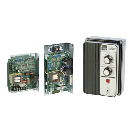
Instructions for Installation and Operation
Type FPM 0810, 0830, and 0850
Permanent Magnet DC Motor Controls
(with driver board only, or with F-B-R board)
SPECIFICATIONS
Input Voltage: . . . . . . . . . . . . . . . . . . . 115 VAC±10%; 50/60 Hz, single phase
Input Current:
Model 0810 . . . . . . . . . . . . . . . . . . . . . . . . . . . . . . . . . . . . . . . . 2.9 Amps AC
Model 0830. . . . . . . . . . . . . . . . . . . . . . . . . . . . . . . . . . . . . . . . 4.2 Amps AC
Model 0850. . . . . . . . . . . . . . . . . . . . . . . . . . . . . . . . . . . . . . . . 9.0 Amps AC
Armature Voltage (nominal) . . . . . . . . . . . . . . . . . . . . . . . . . . . . . 0-130 VDC
Armature Current (max. continuous)
Model 0810 . . . . . . . . . . . . . . . . . . . . . . . . . . . . . . . . . . . . . . . . . . 0.50 Amps
Model 0830. . . . . . . . . . . . . . . . . . . . . . . . . . . . . . . . . . . . . . . . . . 1.25 Amps
Model 0850. . . . . . . . . . . . . . . . . . . . . . . . . . . . . . . . . . . . . . . . . . 2.30 Amps
Model 0810 up to 1/17 HP
Model 0830 up to 1/6 HP
Model 0850 up to 1/3 HP
www.bodine-electric.com
07400156.i
Advertisement

Related Manuals for Bodine Quality IN Motion 0810


Summary of Contents for Bodine Quality IN Motion 0810
- Page 1 Model 0850......... . 2.30 Amps www.bodine-electric.com...
- Page 2 Bodine or to a Bodine Authorized Service Center. Bodine is not responsible for removal, installation, or any other incidental expenses incurred in shipping the products to or from Bodine. This warranty is in lieu of any other expressed or implied warranty – including, but not limited to, any implied warranties of merchantability and/or fitness for a particular use.
- Page 4 IMPORTANT Read this manual completely and carefully. Pay special attention to all warnings, cautions, and safety rules. Failure to follow the instructions could produce safety hazards which could injure personnel or damage the control, motor, or other equipment. If you have any doubts about how to connect the control or motor, refer to the detailed sections of this manual.
-
Page 5: Specifications
SPECIFICATIONS INPUT VOLTAGE .......115VAC ± 10% 50/60 Hz SINGLE PHASE INPUT CURRENT Models 0810 through 0818 ............. 2.9 Amps AC Models 0830 through 0838 ............. 4.2 Amps AC Models 0850 through 0858 ............. 9.0 Amps AC ARMATURE VOLTAGE (Nominal) ............ 0-130 VDC ARMATURE CURRENT (Max. -
Page 6: Safety Precautions
Bodine Electric Company assumes no liability for the customer’s failure to comply with safety requirements and practices. - Page 7 ” * Bodine products are designed and manufactured to comply to applicable safety standards and in particular to those issued by ANSI (American National Standards Institute}, NEMA (National Electrical Manufacturers Association), U.L.
- Page 10 WARNING AVERTISSEMENT This speed control should Ce régulateur de vitesse ne only be installed by a qualified doit être installé que par un technician, electrician or electrical technicien qualifié, un électricien maintenance person familiar ou une personne de maintenance with its operation and associated électrique familiarisé...
- Page 11 NOTE: Any exposed circun boards should be handled in a static-protected area. The feature boards use CMOS circuitry. Static discharge into the feature boards must be avoided. All encased controls accept 1/2-inch liquid tight conduit fittings. For wire sizes and electrical connections refer to the National Electrical Code (NEC)– Article 430–”Motors, Motor Circuits, and Controllers”...
- Page 12 NOTE: This control does not provide motor over temperature protection. The user is responsible for providing this protection in the equipment where this control is used REMARQUE: La détection de la surchau e du moteur n’est pas assurée par cette control.
- Page 13 42A7BEPM 2500 1,2,8 MDA 2.5 Littelfuse Bussmann Figure 2: FPM driver board – Fuse selection and DIP switch settings. Application note: select 42A5-FX (90/130V) models may exceed type FPM current limit. Consult Bodine technical support for more information. E-mail: info@bodine-electric.com.
- Page 14 5. Referring to Fig. 1, identify the barrier terminal block (TB1) on your control’s driver board. Connect the ground wire and motor armature wires to the terminal block. Finally, attach the 115VAC power line to the terminal block. DO NOT connect the 115VAC power line to an external power source at this time.
- Page 16 CONNECTING AN F-B-R KIT If you have purchased a separate electronic Forward-Brake-Reverse Kit (Model 0890) read the installation instructions provided with the Kit and install the Kit before proceeding. CONNECTING THE ELECTRONIC F-B-R BOARD If you are not using an F-B-R Board, proceed to “Operating the Control”on page 20.
- Page 17 All connections described in these instructions are made to socket J7 (on the F-B-R Board) using the color-coded wires from the pre-wired connector provided with your control or F-B-R Kit. Fig. 5 describes the functions of the pins on J7, and matches each pin to a corresponding colored wire from the prewired connector.
-
Page 20: Operating The Control
OPERATING THE CONTROL WARNING AVERTISSEMENT Risk of explosions, fires, or Les risques d’explosion, d’incendie electric shock hazards can be ou de choc électrique peuvent reduced through thermal and être réduits grâce à une protection over-current protection, good thermique et contre les surintensités, maintenance, proper grounding, un bon entretien, une mise à... - Page 21 OPERATING INSTRUCTIONS WARNING AVERTISSEMENT The 115 VAC line cord to the Le cordon d’alimentation de 115 control should be disconnected VCA de la commande doit être before starting. débranché avant de commencer. 1. With input power OFF , set the speed potentiometer at ZERO. If an optional F-B-R switch is used, set it at the BRAKE position.
- Page 22 MAKING INTERNAL ADJUSTMENTS Your control has been factory-adjusted and normally does not require readjustment. If you do not need to readjust the control, proceed to “TROUBLESHOOTING. WARNING AVERTISSEMENT Use a non-metallic or insulated Utilisez un outil de réglage non adjustment tool (such as a plastic- métallique ou isolé...
- Page 23 To increase the minmum speed: turn the MIN trim potentiometer counter- clockwise. This adjustment will increase the maximum speed beyond name- plate speed (2500 or 2000 RPM). The MAX trim potentiometer will need to be readjusted. To allow motor operation at very low speeds: turn the MIN potentiometer slightly counterclockwise.
- Page 24 TORQUE (CURRENT LIMITING ADJUSTMENT The “TORQ” trim potentiometer (Fig. 1) has already been adjusted so that the motor will never see more than 225 to 250 percent of its rated current input. To reduce the maximum current available to the motor: turn TORQ trim potentiometer counterclockwise.
- Page 25 6. Turn the external speed potentiometer to its highest setting (or increase the speed control signal to the maximum value allowed). ACCELERATION ADJUSTMENT The ACCEL trim potentiometer (Fig. 1) controls the speed input response time, thus influencing the motor’s acceleration and deceleration time. The ACCEL trim pot will have an e ect when a speed signal is reduced or increased.
-
Page 26: Troubleshooting
TROUBLESHOOTING WARNING AVERTISSEMENT Disconnect the speed control Débranchez la commande de vitesse from the 115 VAC power source de la source d'alimentation 115 VCA before working on the control, avant de travailler sur la commande, gearmotor, motor, or driven le motoréducteur, le moteur ou equipment. - Page 28 Visit bodine-electric.com for detailed product information Bodine o ers the widest selection of variable-speed AC, permanent magnet DC and brushless DC fractional horsepower gearmotors and motors in the industry. For complete specifications, 3D CAD drawings, or to order online, visit bodine-electric.com.
Need help?
Do you have a question about the Quality IN Motion 0810 and is the answer not in the manual?
Questions and answers