
Related Manuals for ASRock Industrial SBC-370


Summary of Contents for ASRock Industrial SBC-370
- Page 1 SBC-370 User Manual Version 1.0 Published December 26, 2022 Copyright©2022 ASRockInd INC. All rights reserved.
- Page 2 Copyright Notice: No part of this documentation may be reproduced, transcribed, transmitted, or translated in any language, in any form or by any means, except duplication of documentation by the purchaser for backup purpose, without written consent of ASRockInd Inc. Products and corporate names appearing in this documentation may or may not be registered trademarks or copyrights of their respective companies, and are used only for identification or explanation and to the owners’...
- Page 3 The terms HDMI® and HDMI High-Definition Multimedia Interface, and the HDMI logo are trademarks or registered trademarks of HDMI Licensing LLC in the United States and other countries. CAUTION: RISK OF EXPLOSION IF BATTERY IS REPLACED BY AN INCORRECT TYPE. DISPOSE OF USED BATTERIES ACCORDING TO THE INSTRUCTIONS.
-
Page 4: Table Of Contents
Contents Chapter 1 Introduction 1.1 Package Contents 1.2 Specifications 1.3 Motherboard Layout 1.4 I/O Panel Chapter 2 Installation 2.1 Screw Holes 2.2 Pre-installation Precautions 2.3 Installation of Memory Modules (SO-DIMM) 2.4 Expansion Slots 2.5 Jumpers Setup Chapter 3 UEFI SETUP UTILITY 3.1 Introduction 3.1.1 Entering BIOS Setup 3.1.2 UEFI Menu Bar... -
Page 5: Chapter 1 Introduction
SBC-370 Chapter 1 Introduction Thank you for purchasing ASRockInd SBC-370 motherboard, a reliable motherboard produced under ASRockInd’s consistently stringent quality control. It delivers excel- lent performance with robust design conforming to ASRockInd’s commitment to quality and endurance. In this manual, chapter 1 and 2 contain introduction of the motherboard and step-by- step guide to the hardware installation. -
Page 6: Specifications
1.2 Specifications Form 3.5” SBC (5.8-in x 4-in x 0.94-in, 14.7 cm x 10.2 cm x Dimensions Factor 2.40 cm) ® Intel Alder Lake P SoC Processors SBC-370P (i7-1265UE, 2P+8E) Processor SBC-370M (i5-1245UE, 2P+8E) System SBC-370V (i3-1215UE, 2P+4E) Chipset BIOS AMI SPI 256 Mbit PCIe 1 x PCIe x1 Gen3 (Supports up to 10W) - Page 7 SBC-370 HDMI 1 x HDMI2.0b DisplayPort 1 x DP1.4++ Ethernet 2 x 2.5 Gigabit Lan Rear I/O 2 x USB 3.2 Gen2 2 x USB 3.2 Gen2x2 (20G) (Type-C, Support DP1.4a display output) 1 x USB 3.2 Gen 2 2 x USB 2.0 (1 x 2.54 pitch header)
-
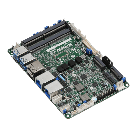
Page 8: Motherboard Layout
SIO_AT1 BLT_PWM2 PNL_PWR1 DACC1 CLRMOS1 CLRMOS2 PCIE_ISOLATION1 DDR4_A1 (Support DDR4 Only) DDR4_B1 (Support DDR4 Only) USB 3.2 Gen2 T: USB3_1 B: USB3_TC_1 RoHS SBC-370 USB 3.2 Gen2 T: USB3_2 B: USB3_TC_2 Industrial BKT_PWR1 BLT_PWM1 USB2_5_6 LAN1 LAN2 USB3_3 SATA3_1 DC_IN1... - Page 9 SBC-370 Bottom : BIOS SIM1...
- Page 10 1 : 3W Audio AMP Output Wafer 2 : PCIE_ISOLATION1 3 : Front Panel Audio Header 4 : DACC1 5 : Chassis Intrusion Headers (CI1, CI2) 6 : SIO_AT1 7 : Clear CMOS Headers (CLRMOS1, CLRMOS2) 8 : CON_LBKLT_CTL Voltage Level (BLT_PWM2) 9 : Panel Power Select (LCD_VCC) (PNL_PWR1) 10 : Backlight &...
-
Page 11: I/O Panel
SBC-370 1.4 I/O Panel RJ45 LAN Port (LAN1) (Supports vPro)* USB3.2 Gen2 Port (USB3_1) USB3.2 Gen2 Port (USB3_2) HDMI Port (HDMI) USB3.2 Gen2 Type-C Port (USB3_TC_2) DisplayPort (DP1) RJ45 LAN Port (LAN2)* USB3.2 Gen2 Type-C Port (USB3_TC_1) * There are two LED next to the LAN port. Please refer to the table below for the LAN port LED indications. -
Page 12: Chapter 2 Installation
Chapter 2 Installation This is a 3.5” SBC (5.8-in x 4-in x 0.94-in, 14.7 cm x 10.2 cm x 2.40 cm) form factor motherboard. Before you install the motherboard, study the configuration of your chassis to ensure that the motherboard fits into it. Make sure to unplug the power cord before installing or removing the motherboard. -
Page 13: Installation Of Memory Modules (So-Dimm)
SBC-370 2.3 Installation of Memory Modules (SO-DIMM) SBC-370 provides two 204-pin DDR4 (Double Data Rate 4) SO-DIMM slots. Step 1. Align a SO-DIMM on the slot such that the notch on the SO-DIMM matches the break on the slot. The SO-DIMM only fits in one correct orientation. It will cause permanent damage to the motherboard and the SO-DIMM if you force the SO-DIMM into the slot at incor- rect orientation. -
Page 14: Expansion Slots
2.4 Expansion Slots There are 1 PCI Express slot, 3 M.2 sockets and 1 SIM socket on this motherboard. PCIE slot: PCIE1 (PCIE 3.0 x1 slot) is used for PCI Express x1 lane width cards. * Supports PCIE devices up to 10W Signal Name +12V +12V... - Page 15 SBC-370 M.2 sockets: 1 x M.2 (Key E, 2230) with PCIe x1, USB 2.0 and CNVi for Wireless. 1 x M.2 (Key B, 3042/3052) with PCIex1 or SATA3 and USB 3.2 and USB 2.0 and SIM for 4G/5G. 1 x M.2 (Key M, 2242/2260/2280) with PCIex4 for SSD M.2 Key-E Socket...
-
Page 16: Jumpers Setup
2.5 Jumpers Setup The illustration shows how jumpers are setup. When the jumper cap is placed on pins, the jumper is “Short.” If no jumper cap is placed on pins, the jumper is “Open. ” The illustration shows a 3-pin jumper whose pin1 and pin2 are “Short”... - Page 17 SBC-370 Clear CMOS Jumpers CLRMOS1 : 1-2 : Normal (3-pin CLRMOS1) Default Clear CMOS 2-3 : Clear CMOS (see p. 4, No. 7) NOTE: CLRMOS1 allows you to clear the data in CMOS. To clear and reset the system parameters to default setup, please turn off the computer and unplug the power cord from the power supply.
- Page 18 Brightness Control Mode 1-2 : From eDP PWM to CON_LBKLT_CTL (3-pin BLT_PWM1) 2-3 : From LVDS PWM to (see p. 4 No. 13) CON_LBKLT_CTL Please set to 1-2 when adjusting brightness by Brightness Control bar under OS. Please set to 2-3 when adjusting brightness by BLT_VOL1. Backlight Power Select Use this to set up the backlight (LCD_BLT_VCC)
- Page 19 SBC-370 2.6 Onboard Headers and Connectors Onboard headers and connectors are NOT jumpers. Do NOT place jumper caps over these headers and connectors. Placing jumper caps over the headers and connectors will cause per- manent damage of the motherboard! Signal Name...
- Page 20 LVDS Panel Connector Signal Name Signal Name LCD_BLT_VCC LCD_BLT_VCC (40-pin LVDS1) CON_LBKLT_CTL LCD_BLT_VCC (see p. 4 No. 12) CON_LBKLT_EN LVDS_B_CLK# LVDS_B_CLK LVDS_B_DATA3 DPLVDD_EN LVDS_B_DATA3# LVDS_B_DATA2# LVDS_B_DATA2 LVDS_B_DATA1 LVDS_B_DATA1# LVDS_B_DATA0# LVDS_B_DATA0 LVDS_A_CLK LVDS_A_CLK# LVDS_A_DATA3# LVDS_A_DATA3 LVDS_A_DATA2 LVDS_A_DATA2# LVDS_A_DATA1# LVDS_A_DATA1 LVDS_A_DATA0 LVDS_A_DATA0# +3.3V LCD_VCC LCD_VCC...
- Page 21 SBC-370 SATA Power Output Connector +12V (4-pin SATA_PWR1) (see p. 4 No. 21) Digital Input/Output Pin Header (10-pin JGPIO1) (see p. 4 No. 23) Signal PIN Signal Name PIN Signal Name PIN PIN Signal Name PIN Signal Name Name GPP_B15...
- Page 22 HDLED (Hard Drive Activity LED): Connect to the hard drive activity LED on the chassis front panel. The LED is on when the hard drive is reading or writing data. The front panel design may differ by chassis. A front panel module mainly consists of power switch, reset switch, power LED, hard drive activity LED, speaker and etc.
- Page 23 SBC-370 This motherboard supports RS232/422/485 on COM1, 4, 3 ports. Please refer to below table for the pin definition. In addition, COM1, 4, 3 ports (RS232/422/485) can be adjusted in BIOS setup utility > Advanced Screen > Super IO Configuration. You may refer to page 32 for details.
- Page 24 ESPI Header Signal Name (20-pin ESPI1) (see p. 5 No. 33) ESPI_ALERT# Internal use Internal use +3VSB ESPI_IO3 ESPI_IO2 ESPI_IO1 ESPI_IO0 SMB_DATA SMB_CLK ESPI_RESET# ESPI_CS# ESPI_CLK...
-
Page 25: Chapter 3 Uefi Setup Utility
Chapter 3 UEFI SETUP UTILITY 3.1 Introduction ASRock Industrial UEFI (Unified Extensible Firmware Interface) is a BIOS utility which offers tweak-friendly options in an advanced viewing interface. The UEFI system works with a USB mouse and offers users a faster, sleeker experience. -
Page 26: Uefi Menu Bar
3.1.2 UEFI Menu Bar The top of the screen has a menu bar with the following selections: Main For setting system time/date information For advanced system configurations Advanced H/W Monitor Displays current hardware status Security For security settings Boot For configuring boot settings and boot priority Exit Exit the current screen or the UEFI Setup Utility Because the UEFI software is constantly being updated, the following UEFI setup... -
Page 27: Navigation Keys
SBC-370 3.1.3 Navigation Keys Use < > key or < > key to choose among the selections on the menu bar, and use < > key or < > key to move the cursor up or down to select items, then press <Enter>... -
Page 28: Main Screen (Advanced Mode)
3.2 Main Screen (Advanced Mode) When you enter the UEFI SETUP UTILITY, the Main screen will appear and display the system overview. Because the UEFI software is constantly being updated, the following UEFI setup screens and descriptions are for reference purpose only, and they may not exactly match what you see on your screen. -
Page 29: Advanced Screen
SBC-370 3.3 Advanced Screen In this section, you may set the configurations for the following items: CPU Configuration, Chipset Configuration, Storage Configuration, Super IO Configura- tion, ACPI Configuration, USB Configuration and Trusted Computing. Setting wrong values in this section may cause the system to malfunction. -
Page 30: Cpu Configuration
3.3.1 CPU Configuration Intel Hyper Threading Technology Intel Hyper Threading Technology allows multiple threads to run on each core, so that the overall performance on threaded software is improved. Configuration options: [Enabled] [Disabled] Active Processor P-Cores Allows you to select the number of cores to enable in each processor package. Active Processor E-Cores Allows you to select the number of E-Cores to enable in each processor package. - Page 31 SBC-370 Intel Virtualization Technology Intel Virtualization Technology allows a platform to run multiple operating systems and applications in independent partitions, so that one computer system can function as multiple virtual systems. Configuration options: [Enabled] [Disabled] Intel SpeedStep Technology Intel SpeedStep technology allows processors to switch between multiple frequen- cies and voltage points for better power saving and heat dissipation.
-
Page 32: Chipset Configuration
3.3.2 Chipset Configuration VT-d Intel® Virtualization Technology for Directed I/O helps your virtual machine monitor better utilize hardware by improving application compatibility and reliability, and providing additional levels of manageability, security, isolation, and I/O performance. Configuration options: [Enabled] [Disabled] Share Memory Share memory allows you to configure the size of memory that is allocated to the integrated graphics processor when the system boots up. - Page 33 SBC-370 Change the setting from [Enabled] to [Disabled], and then press <F10> to save the setting and restart the system. Likewise, the default value of Active LVDS is changed to [Disabled] (F9 load default is also set to [Disabled]). Onboard LAN1 This allows you to enable or disable the Onboard LAN1 feature.
-
Page 34: Storage Configuration
3.3.3 Storage Configuration VMD Configuration Press [Enter] to view the followings items for VMD configurations. - Page 35 SBC-370 SATA Controller(s) Allows you to enable or disable the SATA controllers. Configuration options: [Enabled] [Disabled] SATA Mode Selection AHCI: Supports new features that improve performance. Configuration option: [AHCI] Hybrid Storage Detection and Configuration Mode Hybrid Storage Detection and Configuration Mode allows you to select Hybrid Storage Detection and Configuration Mode.
-
Page 36: Super Io Configuration
3.3.4 Super IO Configuration COM1 Configuration Use this to set parameters of COM1. Type Select Use this to select COM1 port type: [RS232], [RS422] or [RS485]. COM3 Configuration Use this to set parameters of COM3. Type Select Use this to select COM1 port type: [RS232], [RS422] or [RS485]. COM4 Configuration Use this to set parameters of COM4. -
Page 37: Acpi Configuration
SBC-370 3.3.5 ACPI Configuration Suspend to RAM Suspend to RAM allows you to select [Disabled] for ACPI suspend type S1. It is recommended to select [Auto] for ACPI S3 power saving. Configuration options: [Auto] [Disabled] Onboard LAN Power On Use this item to enable or disable onboard LAN to turn on the system from the power-soft-off mode. -
Page 38: Usb Configuration
3.3.6 USB Configuration USB Power Control Use this option to control USB power. M.2 Key_B USB Function Use this item to enable or disable M.2 Key_B USB Configuration. Configuration options: [Enabled] [Disabled]... -
Page 39: Trusted Computing
SBC-370 3.3.7 Trusted Computing NOTE: Options vary depending on the version of your connected TPM module. Security Device Support Security Device Support allows you to enable or disable BIOS support for security device. O.S. will not show Security Device. TCG EFI protocol and INT1A interface will not be available. - Page 40 Pending Operation Pending Operation allows you to schedule an Operation for the Security Device. NOTE: Your computer will reboot during restart in order to change State of the Device. Configuration options: [None] [TPM Clear] Platform Hierarchy This item allows you to enable or disable Platform Hierarchy. Configuration options: [Enabled] [Disabled] Storage Hierarchy This item allows you to enable or disable Storage Hierarchy.
-
Page 41: Hardware Health Event Monitoring Screen
SBC-370 3.4 Hardware Health Event Monitoring Screen This section allows you to monitor the status of the hardware on your system, including the parameters of the CPU temperature, motherboard temperature, fan speed, chassis fan speed, and the critical voltage. NOTE: Options vary depending on the features of your motherboard. -
Page 42: Security Screen
3.5 Security Screen In this section you may set or change the supervisor/user password for the system. You may also clear the user password. Supervisor Password Set or change the password for the administrator account. Only the administrator has authority to change the settings in the UEFI Setup Utility. Leave it blank and press enter to remove the password. -
Page 43: Boot Screen
SBC-370 3.6 Boot Screen This section displays the available devices on your system for you to configure the boot settings and the boot priority. Boot Option #1 The item allows you to set the system boot order. Boot Option #2 The item allows you to set the system boot order. - Page 44 Bootup Num-Lock The item allows you to select whether Num Lock should be turned on or off when the system boots up. Configuration options: [On] [Off] Full Screen Logo [Enabled] Select this item to display the boot logo. [Disabled] Select this item to show normal POST messages.
-
Page 45: Exit Screen
SBC-370 3.7 Exit Screen Save Changes and Exit When you select this option, the following message “Save configuration changes and exit setup?” will pop out. Press <F10> key or select [Yes] to save the changes and exit the UEFI SETUP UTILITY.
Need help?
Do you have a question about the SBC-370 and is the answer not in the manual?
Questions and answers