
Subscribe to Our Youtube Channel
Related Manuals for Presys DCY-2057

Summary of Contents for Presys DCY-2057
- Page 1 PRESYS Instruments DCY-2057 Pressure Controller PRESYS DCY-2057 TECHNICAL MANUAL...
-
Page 2: Table Of Contents
PRESYS Instruments DCY - 2057 Pressure Controller TABLE OF CONTENTS Page 1 - Introduction..................1.1 - Description..................1.2 - Order Code Number................ 1.3 - Technical Specifications..............2 - Installation................... 2.1 - Mechanical Installation..............2.2 - Electrical Installation................ 2.3 - Process Input Signal Connection............. -
Page 3: Introduction
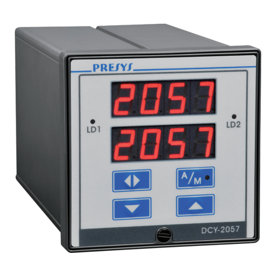
It is provided with several control modes: ON-OFF, PID (with all its combinations), time proportioning, programmable setpoint, cascade and remote setpoint input. The DCY-2057 Controller is provided with auto-tune algorithm to compute the PID parameters for optimizing control capabilities. It incorporates all standard control characteristics, such as: auto-manual bumpless transfer, output saturation, remote setpoint and programmable setpoint up to ten segments, protection against integral saturation, etc. - Page 4 DCY-2057 Fig. 1 - DCY - 2057 Controller Front Panel. On the instrument front panel there are two red displays configurable with the decimal point for up to four high visibility digits.
-
Page 5: Order Code Number
(if desired, specify this information so that all the configuration can be made by PRESYS). Note 2: Other hardware and software features can be available under previous consult. -
Page 6: Technical Specifications
PRESYS Instruments DCY - 2057 Pressure Controller Code Example: 1) DCY - 2057 - 6 - 1 - 1 - 8 - 1 - 2 - 1 - 4 - 1 - 1 - 1 - 0 - 0 This code defines a DCY - 2057 Controller with two pressure inputs, the first in the 0 to 100 psi range, gage pressure and use with air, the second in the 0 to 500 psi range, gage pressure and use with fluid. - Page 7 PRESYS Instruments DCY - 2057 Pressure Controller Input sensor Span Sensor lower higher limit limit 250 mmH 0.355 1 psi 1.000 Pressure 5 psi 5.000 15 psi 15.00 30 psi 30.00 100 psi 100.0 250 psi 250.0 500 psi 500.0...
- Page 8 PRESYS Instruments DCY - 2057 Pressure Controller Control outputs: . Analog output 4 to 20mAdc, 1 to 5VDC, 0 to 10VDC, use of optional cards with plug-in fitting foreseen for up to two 300 VAC modules galvanically isolated from inputs and power supply. Maximum load of 750Ω.
- Page 9 PRESYS Instruments DCY - 2057 Pressure Controller Square root extraction: ± 0.5% of readings, for input above 10% of span. 0 to 5% of programmable Cut- off. Cold junction compensation: ± 2.0°C in the range from 0 to 50°C of ambient temperature.
-
Page 10: Installation
PRESYS Instruments DCY - 2057 Pressure Controller 2 - Installation 2.1 - Mechanical Installation The DCY - 2057 Controller front panel has 1/4 DIN size (96 X 96 mm). It is fixed by the rails which press it against the back side of the panel. -
Page 11: Process Input Signal Connection
PRESYS Instruments DCY - 2057 Pressure Controller Fig. 3 - DCY-2057 Controller Terminals 2.3 - Process Input Signal Connections Pressure inputs 1and 2 (optional), shown in figure 3, require pneumatic / hydraulic connection with junction for 1/4” plastic tube for use with air or 1/4” NPTF for use with other fluids. -
Page 12: Thermocouple Connection
PRESYS Instruments DCY - 2057 Pressure Controller 2.3.1 - Thermocouple Connection Connect the thermocouple to terminals 5(+) and 6(-) of input 2 as shown in figure 4. Use appropriate compensating cables with the same material of the thermocouple in order to connect it to the instrument. Check if the thermocouple polarity is equal to those of the terminals. -
Page 13: Milliampere Input
PRESYS Instruments DCY - 2057 Pressure Controller Fig. 5 - RTD Connection 2.3.3 - Milliampere Input A standard 4 to 20mA current source can be applied between terminals 4(+) and 6(-) of input 2; this current signal can originate from an externally powered Transmitter. - Page 14 PRESYS Instruments DCY - 2057 Pressure Controller Fig. 6 - Current source Connection Installation Page 12...
-
Page 15: V Or Mv Input
PRESYS Instruments DCY - 2057 Pressure Controller 2.3.4 - mV or V Input Either a 0 to 55mVDC or a 0 to 5VDC voltage must be applied between terminals 5(+) and 6(-) of input 2. A 0 to 10VDC voltage must be applied between terminals 4(+) and 6(-) of input 2. - Page 16 PRESYS Instruments DCY - 2057 Pressure Controller In case of outputs 1 and 2 we can have six types of different outputs between the current I/O terminals: current (4 to 20mA), voltage (0 to 5VDC), voltage (0 to 10VDC), SPST relay, open collector voltage and solid state relay.
- Page 17 PRESYS Instruments DCY - 2057 Pressure Controller TERMINALS FUNCTION INTERNAL DEVICE +24V OUTPUT 2 NC * Alarm SPST Logic +24V OUTPUT 3 Alarm Logic SPDT +24V OUTPUT 4 Alarm SPDT Logic (*) Relay contact states shown are valid for SAFE option selected (see section 3.2 on Configuration), Controller powered on and non-alarm condition.
-
Page 18: Connection Diagram
PRESYS Instruments DCY - 2057 Pressure Controller 2.5 - Connection Diagram Installation Page 16... -
Page 19: Communication
Instruments DCY - 2057 Pressure Controller 2.6 - Communication DCY-2057 Controller communicates with computers through RS-232 or RS-422/485 and with use of a MODBUS protocol communication software, when the optional communication modules are installed and the communication parameters are configured. -
Page 20: Operation
DCY - 2057 Pressure Controller 3 - Operation 3.1 - Normal operation The DCY-2057 Controller has two modes of operation: normal mode and configuration mode. In normal operation mode we can further have the automatic operation mode and the manual operation mode. - Page 21 PRESYS Instruments DCY - 2057 Pressure Controller Operation Level ENT2, SP2 and OUT2 are not shown when channel 2 is disabled Fig. 10 - Options for Operation Level Operation Page 19...
- Page 22 PRESYS Instruments DCY - 2057 Pressure Controller The display shows 4 types of configuration for each channel. The configuration screens on the previous figure are identified by the numbers 1, 2, 3 and 4 for channel Upon changing to manual mode (green LED on) the configuration screen shifts to type 3.
-
Page 23: Configuration
Instruments DCY - 2057 Pressure Controller 3.2 - Configuration The DCY-2057 Controller can be configured with a password system to prevent unauthorized people from altering critical process parameters. Therefore, whenever the key ENTER is pressed, with the mnemonic CONF (Configuration) showing on the upper display and depending on configuration, one of... - Page 24 (E2PROM and NVRAM) and determine the instrument normal operation. Through configuration parameters the user may adapt the instrument according to his requirements. Normally the DCY-2057 Controller is factory configured and the user is not expected to enter the configuration mode.
- Page 25 PRESYS Instruments DCY - 2057 Pressure Controller Note: in the following diagrams, the Controller displays are represented by rectangles in response to the selection ENTER, UP and DOWN keys. T h is le v e l is v a lid o n ly fo r v e r s io n w ith c o m m u n ic a tio n .
-
Page 26: Level 1 - General
PRESYS Instruments DCY - 2057 Pressure Controller 3.2.1 - Level 1 - General In level 1 we have the options: TAG, SOFT, PASS, INDIC, SP.Li, PO.BR, ST.CO, LED1 and LED2 (see figure 13). TAG - this option enables a numerical identification for the instrument. The... - Page 27 PRESYS Instruments DCY - 2057 Pressure Controller LED1 - it allows the association of LED1 in the Controller front panel to the control loop 1 (C - 1), the control loop 2 (C - 2), the alarm relay 2 (rl. 2), the alarm relay 3 (rl. 3) or the alarm relay 4 (N.4).
-
Page 28: Level 2 - Inputs
PRESYS Instruments DCY - 2057 Pressure Controller The adjustable parameter span shown on figure 13 is given below. Mnemonic Parameter Adjustable Span Factory Unit Value instrument -999 to 9999 2057 ------------- identification SOFT software version ------------- 1.00 ------------- VALUE user password... - Page 29 PRESYS Instruments DCY - 2057 Pressure Controller (1) FOLLOWS THE SAME OPTIONS OF CH-2 EXCEPT THOSE INDICATED BY *. (2) PRESENTED ONLY FOR LINEAR SENSORS AND PRESSURE. (3) PRESENTED ONLY FOR TEMPERATURE SENSORS. Fig. 14 - INPUT Level Options Operation...
- Page 30 PRESYS Instruments DCY - 2057 Pressure Controller DIRECT - enables a user-configurable scale for the pressure sensor. When YES is selected, the indication scale on display is the own scale of the pressure sensor (for instance: 0 to 5.000 psi; 0 to 250.0 psi, etc.). In case the NO option is selected to the direct mode, it takes the scale configured by the user, by means of the Lim Low, Lim High, Eng Low and Eng High mnemonics.
- Page 31 PRESYS Instruments DCY - 2057 Pressure Controller given in % of full scale associated to the Eng Low indication on the display, and Lim High corresponds to the value of the electrical signal given in % of full scale associated to the Eng High indication on the display.
-
Page 32: Level 3 - Outputs
PRESYS Instruments DCY - 2057 Pressure Controller DEC PT. - sets the decimal point to exhibit the engineering units on the upper display. Up to three decimal digits may be set for pressures and linear processes, whereas temperature sensors may have one or no decimal digit. - Page 33 PRESYS Instruments DCY - 2057 Pressure Controller (1) FOLLOWS THE SAME OPTIONS FOR OUTPUT 2 (2) SAME AS 5V OPTION Fig. 17 - OUTPUT Level Options The adjustable parameter ranges shown on figure 17 are given below. Mnemonic Parameter Adjustable...
-
Page 34: Level 4 - Alarms
PRESYS Instruments DCY - 2057 Pressure Controller Whenever configured for current and voltage, the control outputs 1 and 2 should have their limits specified by the Lim Low and Lim High parameters. Note that Lim Low and Lim High are expressed as a percentage of output full scale and that the output signal saturates at those points. - Page 35 PRESYS Instruments DCY - 2057 Pressure Controller SAFE - provides relay safety. Relay safety condition means that relay coils are energized when the instrument is powered and are de-energized under an alarm condition or in the event of a power failure.
-
Page 36: Level 5 - Control
DCY - 2057 Pressure Controller 3.2.5 - Level 5 - Control The DCY-2057 Controller can control up to two control loops. It is on Configuration level 5 that the desired control mode is selected for the control loops 1 and 2 (see figure 20). - Page 37 PRESYS Instruments DCY - 2057 Pressure Controller (1) FOLLOW THE SAME OPTIONS FOR CTRL1. Fig. 20 - CONTROL Level Options Operation Page 35...
- Page 38 (see section on Connection of Control Output Signals). In the DCY-2057 Controller the upper and lower displays always show the controlled variable and the setpoint/output, respectively, for the control loop 1 or 2. The values shown on the upper and lower displays will always correspond to the same control block 1 or 2.
- Page 39 This type of control uses two Controllers. For the DCY-2057 Controller, control block 1 will act as the master Controller and its output will provide the slave Controller with the setpoint which will be the control block 2, as illustrated on figure 23, below.
- Page 40 PRESYS Instruments DCY - 2057 Pressure Controller ON/OFF Control ON/OFF - associates the ON/OFF control mode with the related control block, 1 or 2 (or both). ACTION - this option determines the direction of the control action (direct or reverse).
- Page 41 PRESYS Instruments DCY - 2057 Pressure Controller PID control PID - it associates the PID control mode with the related control block, 1 or 2 (or both). ACTION - this option determines the direction of the control action (direct or reverse).
- Page 42 It is used to eliminate oscillations. Note that on the DCY-2057 Controller the deviate is applied to the controlled variable; this inhibits the derivative action whenever the setpoint only is altered.
-
Page 43: Level 6 - Tune
0 to 99.99 3.2.6 - Level 6 - Tune The DCY-2057 Controller can apply PID control algorithms both for control loop 1 and for control loop 2. The PID parameters: Gain (GAIN), Integrative Rate (INT) and Derivative Time (DER) are adjustable over a wide span of values in order to accommodate several processes with varying characteristics. - Page 44 PRESYS Instruments DCY - 2057 Pressure Controller Warning: Whenever the derivative time (DER) is configured as zero, the auto-tune algorithm will compute the parameters only for a PI control. Before carrying out the auto-tune, the user should select the proper control action (reverse or direct) to meet the requirements of this process.
- Page 45 PRESYS Instruments DCY - 2057 Pressure Controller Hyst - This is the parameter determining when the output should be changed. Whenever the control variable crosses the upper and lower hysteresis limits, the Controller output should cause the D.Out value to vary for the more or for less from its original value.
- Page 46 PRESYS Instruments DCY - 2057 Pressure Controller Fig. 26 - TUNE Level Options The adjustable parameter ranges shown on figure 26 are given below. Mnemonic Parameter Adjustable Factory Units Range Value D.Out square wave 0 to 100.0 10.0 amplitude Hyst...
- Page 47 PRESYS Instruments DCY - 2057 Pressure Controller Manual PID adjustment The manual adjustment of the PID parameters will be based on the Method of ultimate sensitivity developed by Ziegler and Nichols. By this method, the optimum PID adjustment will be that in which the process reaction curve shows consecutive oscillations peaks with amplitudes at the rate of 1/4.
-
Page 48: Level 7 - Setp (Programmable Setpoint)
DCY - 2057 Pressure Controller 3.2.7 - Level 7 - SetP (Programmable Setpoint) The DCY-2057 Controller can run a program which generates, repeatedly, up to ten setpoint values. The setpoint values, the time taken to reach these values and the number of times this setpoint sequence should be repeated are parameters selected by the user within Configuration level 7. - Page 49 PRESYS Instruments DCY - 2057 Pressure Controller The options of level 7 are shown on figure 29, below. Fig. 29 - Programmable Setpoint Level Options STAT (State) - it allows the user to activate the programmable setpoint (ON), disable the programmable setpoint (OFF) or to indefinitely suspend (SUSPENDED) setpoint execution;...
- Page 50 PRESYS Instruments DCY - 2057 Pressure Controller COUNT - this is the parameter programmed by the user which determines the number of times the setpoint sequence should be repeated. If COUNT is programmble at 250 the programmable setpoint is continuously executed. While the...
-
Page 51: Level 8 Calibration
PRESYS Instruments DCY - 2057 Pressure Controller 3.2.8 - Level 8 Calibration Level 8 is described in section 4.5 on Calibration. 3.2.9 - Level 9 - RS Refer to the communication manual. Maintenance Page 49... -
Page 52: Maintenance
PRESYS Instruments DCY - 2057 Pressure Controller 4.0 - Maintenance 4.1 - Controller Hardware The Controller maintenance requires the user to have access to the hardware of the instrument. The Controller hardware consists of three main boards: Display Board, CPU Board and Power Supply Board. The three -board system is fixed to the aluminum case by a screw on the lower part of the front-panel. -
Page 53: Hardware Configuration
DCY - 2057 Pressure Controller 4.2 - Hardware Configuration This section applies only to DCY-2057 Controllers which do not have a pressure sensor installed in input 2. In this case, input 2 is an universal standard analogic input which must be configured according to the explanation given below. -
Page 54: Snubber Use For Relay
PRESYS Instruments DCY - 2057 Pressure Controller (*) In the case of input under a voltage from 0 to 10V the second factory supplied jumper should be stored by the user away from the instrument or simply engaged to one of the connector pins, in a dummy position as illustrated on figure 32. -
Page 55: Optional Module Connection
4.4 - Optional Module Connections The DCY-2057 Controller may be provided with up to four output signals plus communication. For that purpose, the corresponding optional modules should be installed inside the instrument. By opening the Controllers as explained in section 4.1, access is gained to 4 plug-in connections on the Power Supply Board, plus one... - Page 56 PRESYS Instruments DCY - 2057 Pressure Controller The plug-in connections on the Power Supply Board are called MOD 1, MOD 2, MOD 3 and MOD 4, and are, respectively, the signal counterparts for output 1, output 2, output 3 and output 4, on the Controllers I/O terminals shown on figure 3.
- Page 57 PRESYS Instruments DCY - 2057 Pressure Controller Analog type output Jumpers 4 to 20mA* 1 to 5V 0 to 10V Table 3 - Analog Type Output Jumper Configuration (*) In the case of an analog output for 4 to 20mA current, the supplied jumper should be stored away from the instrument or engaged to just one of the connector pins, in a dummy position, similar to that illustrated on figure 32.
-
Page 58: Calibration
Instruments DCY - 2057 Pressure Controller 4.5 - Calibration The DCY-2057 Controller is accurately calibrated at factory and will not require periodic recalibration under normal conditions. If, for any reason, a recalibration is required, follow the procedure described below. Disconnect the process signals from the Controller I/O terminals. - Page 59 PRESYS Instruments DCY - 2057 Pressure Controller It is possible to calibrate only one point without rendering invalid the other points already calibrated, in case the calibration of this point was not carried out properly. In order to return to normal operation move back through the hierarchical levels until reaching level zero.
- Page 60 PRESYS Instruments DCY - 2057 Pressure Controller Calibration of Pressure Input In order to calibrate the pressure input apply the proper pressure to the sensor to be calibrated. References given in psi / mmH O are listed below for each type of sensor.
- Page 61 PRESYS Instruments DCY - 2057 Pressure Controller • 15 psi Sensor Reference Mnemonic 0.000 psi 0psi 3.000 psi 3psi 6.000 psi 6psi 9.000 psi 9psi 12.000 psi 12psi 15.000 psi 15psi • 30 psi Sensor Reference Mnemonic 0.00 psi 0psi 6.00 psi...
- Page 62 PRESYS Instruments DCY - 2057 Pressure Controller • 500 psi Sensor Reference Mnemonic 0.00 psi 0psi 100.00 psi 100psi 200.00 psi 200psi 300.00 psi 300psi 400.00 psi 400psi 500.00 psi 500psi • 1000 psi Sensor Reference Mnemonic 0.0 psi 0psi 200.0 psi...
- Page 63 PRESYS Instruments DCY - 2057 Pressure Controller Reference Mnemonic 0.0000V C. 0V 5.000V C. 5V Table 6 - Required voltages for the calibration of voltage inputs from 0 to 5V Calibration of voltage input (0 to 10V) In order to calibrate the voltage input at 0 to 10V connect an accurate DC voltage source to channel 2 (terminals 4(+) and 6(-)).
- Page 64 PRESYS Instruments DCY - 2057 Pressure Controller By pressing ENTER after the mnemonic CJC the program automatically starts computing the cold junction temperature. During this period the display flashes the mnemonic CAL. After approximately 16 seconds the program completes the computation of the cold junction temperature and shows the result on the display, in °C.
- Page 65 PRESYS Instruments DCY - 2057 Pressure Controller Make sure the input type to be used for the output calibration has already been properly calibrated. Make the connections listed in table 10 according to which output and output type should be calibrated.
-
Page 66: Hardware Maintenance Instructions
PRESYS Instruments DCY - 2057 Pressure Controller 4.6 - Hardware Maintenance Instructions Prior to returning the instrument to factory check the following possible causes of instrument malfunction. Instrument showing display errors After turning on the equipment start the test routine to check the RAM and E2PROM integrity. - Page 67 PRESYS Instruments DCY - 2057 Pressure Controller Check if the voltages on flat cable 1 as shown in figure 38 are close to values in table 11 and if they reach the CPU Board. Points of Flat-cable 1 Voltages Between point 1(-) and point 2(+)
-
Page 68: List Of Components
PRESYS Instruments DCY - 2057 Pressure Controller 4.7 - List of Components Display Board Code Components Reference 01.05.0056-20 Display Board - DCY 2057 --------------------- 01.07.0002-21 Display 14mm DP1,2,3,4,5,6,7,8 01.04.0001-21 Diode 1N4002 D1,2 01.07.0004-21 Led 3mm (Green) 01.07.0005-21 Led 3mm (Red) D4,5 01.09.0013-21... - Page 69 01010034-21 NVRAM X24C45P 01.01.0019-21 4051 01.01.0022-21 74HC138 01.01.0023-21 74HC365 01.01.0022-21 74HC138 01.01.0023-21 74HC365 01.01.0024-21 74HC373 U5,9,11,12 01.01.0025-21 Presys SY-01 01.01.0026-21 AD706 01.01.0027-21 Presys SY-03 01.16.0001-11 Crystal 11.0592 MHz 01.09.0015-21 Transistor BC 337-25 01.09.0013-21 Transistor BC 327-25 Q2,3,4 01.04.0003-21 Diode 1N4148 D1,2 01.04.0005-21...
- Page 70 PRESYS Instruments DCY - 2057 Pressure Controller Code Components Reference 01.02.0104-21 Resistor 3K32 01.02.0046-21 Resistor 40K2 01.02.0036-21 Resistor 8K66 01.02.0098-21 Resistor 10M R31,33 01.02.0013-21 Resistor 249R R32,34 01.02.0052-21 Resistor 100K 01.02.0092-21 Resistor 01.02.0024-21 Resistor 01.02.0031-21 Resistor 4K99 R7,8,9 01.17.0002-21 Jumper Selected 01.17.0003-21...
- Page 71 PRESYS Instruments DCY - 2057 Pressure Controller Code Components Reference 01.03.0046-21 Tantalum capacitor 1µFX35V C 2, 3 01.02.0080-21 Resistor 4K7 5% 01.02.0024-21 Resistor 2K 1% R 2, 9 01.02.0038-21 Resistor 10K 1% 01.02.0013-21 Resistor 249R 1% R10,11 01.02.0008-21 Resistor 49R9 1% 01.02.0010-21...
-
Page 72: List Of Recommended Spare Components
Display DP1, 2, 3, 4, 5, 6, 7, 8 Power Supply Board IRF 822 UC 3842 Fuse 1A LM 1458N I/O Terminal Board AD 592 CPU Board 4051 Presys SY-02 Reference diode LM-336/ 5V Technical Manual Code 02.10.0008-21 Engineering Units Card Code 02.10.0003.21 Maintenance Page 70... - Page 73 PRESYS INSTRUMENTOS E SISTEMAS LTDA. RUA LUIZ DA COSTA RAMOS, 260 - SAUDE SAO PAULO SP BRAZIL 9001 04157-020 - PHONE +55 (11) 5073.1900 - FAX +55 (11) 5073.3366...
Need help?
Do you have a question about the DCY-2057 and is the answer not in the manual?
Questions and answers