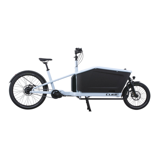
Cube Cargo Hybrid Assembly Instructions Manual
Hide thumbs
Also See for Cargo Hybrid:
- Original operating instructions (72 pages) ,
- Original operating instructions (1195 pages)
Advertisement
Quick Links
Assembly instructions for CUBE Cargo Hybrid
!
ATTENTION:
The executing specialist dealer is responsible and liable for the proper final assembly.
Work on the steering assembly must be carried out by qualified personnel only.
Only the connecting elements supplied in the accessory pack, replacement screws or nuts of the
appropriate strength class may be used.
1
Version 2 / 09.22
Advertisement

Related Manuals for Cube Cargo Hybrid


Summary of Contents for Cube Cargo Hybrid
- Page 1 Assembly instructions for CUBE Cargo Hybrid ATTENTION: The executing specialist dealer is responsible and liable for the proper final assembly. Work on the steering assembly must be carried out by qualified personnel only. Only the connecting elements supplied in the accessory pack, replacement screws or nuts of the appropriate strength class may be used.
- Page 2 Scope of delivery • Front part • Rear part • Upper frame right + left • Steering components • Box right + left • Accessory pack with all small parts required for final assembly • Small parts for connecting the brake cable Version description assembly instruction Version number Change to previous version...
- Page 3 Index: Assembly instructions for initial assembly Other applicable documents Required qualification Safety instructions Assembly instruction for initial assembly Connection of front and rear part Connecting the front brake line Connecting the light cable Putting on the two box halves and the top frame Steering assembly Mounting the 2 base plate screws Assembly instructions for maintenance work...
-
Page 4: Other Applicable Documents
Please read these assembly instructions and all other applicable documents, especially the safety instructions, carefully and completely before you assemble the Cargo Hybrid. If you do not follow these assembly instructions and all other applicable documents, you could injure yourself and other people and/or cause damage to property. -
Page 5: Required Qualification
The specialist dealer is responsible for ensuring that his employees are properly qualified. If unqualified personnel carry out work on the Cargo Hybrid or are within the hazard zone of the Cargo Hybrid, dangers arise which can cause serious injuries and material damage. -
Page 6: Safety Instructions
4. Safety instructions These assembly instructions must be read and understood before starting work in order to ensure safe handling of the Cargo Hybrid. The safety instructions must be observed! if you disregard the safety instructions, you endanger yourself and others. All components of the Cargo Hybrid, especially safety devices, must be correctly assembled to ensure proper operation. - Page 7 Assembly instructions for initial assembly Connection the front and rear parts Version 2 / 09.22...
- Page 8 • Cylinder head screw ISO 4762 M10x35 strength class 10.9 (8x) or higher tightening torque 55 Nm • Nut ISO 7040 M10 strength class 10 (8x) • Use ISO 7090 M10 (16x) washers on both sides of the connecting plate Version 2 / 09.22...
- Page 9 Connecting the front brake hose 5.2.1 Routing the brake hose • Thread the brake hose through the holding eyelet (1), hose entry (2) and hose exit (3) Brake hose must not obstruct the lever part (4) when steering Route the brake hose close to the frame Version 2 / 09.22...
- Page 10 5.2.2 Connecting the brake hose to the brake lever • Analog Online Tutorial: • https://www.magura.com/en/compo nents/techcenter/ Videos Delivery condition: • Sealed hose end (brake body side) • Sealed hose end brake lever side Procedure: 1. Turn the brake lever upwards and fix it lightly 2.
- Page 11 5. Loosen the connection screw (2) with an 8mm open-end wrench 6. Remove and dispose of the hose end 7. Hold the brake body end of the brake hose with the sealed opening pointing upwards and cut it off just behind the sealing clamp 8.
- Page 12 9. Insert barb (4) and tap in with a hammer 10. Barb must be flush with the hose 11. Push rubber cover (1), black connection bolt with fine thread (2) and olive (3) onto the hose 12. Insert brake hose into brake lever, holding connecting parts back to begin with 13.
- Page 13 14. Keep brake hose pressed into brake lever 15. Screw in connection bolt by hand, tighten with 4Nm 16. Slide rubber cover over the connection bolt once more 17. Check brake for safe operation! 18. Turn brake lever back into driving position and tighten Version 2 / 09.22...
- Page 14 5.3 Connecting the light cable 1. Remove batteries to disconnect power supply 2. Thread the light cable coming from the motor through the tension holder (1) and the opening by the angle plate (2) Version 2 / 09.22...
- Page 15 3. Connect the two ends of the light cable by means of cable lugs or heat-shrink tube butt connectors The connection must be waterproof. Version 2 / 09.22...
- Page 16 The light cable and brake hose must be routed close to the frame and must not hinder the movement of the steering components! Non-observance can lead to accidents. Version 2 / 09.22...
- Page 17 Mounting the two box halves, assembling the upper frame • ISO 7380 M6x50 10.9 (8x) • 7 Nm Version 2 / 09.22...
- Page 18 Before tightening, press the upper frame halves towards the middle of the bike and hold them in position, in order to clamp the box halves between the main and upper frame and prevent rattling. Slotted holes in the upper frame allow for shifting. Version 2 / 09.22...
- Page 19 Assembling the steering 5.5.1 Connecting the steering rod to the rear headset 5.5.2 Connecting the steering rod to the front headset 5.5.3 Checking the steering stop 5.5.4 Aligning handlebars and front wheel 5.5.5 Mounting the 2 base plate screws Fork clamp Front headset Steering shaft with...
- Page 20 5.5.1 Connecting the steering rod to the rear headset Washer ISO 7091 M10x2 (2x) Split pin 2,5x20 Screw with split pin hole ISO7380 M10x55 Nut ISO 7040 M10 Washer ISO 7091 M10x2 (1x) Tighten the srew with split pin hole ISO 7380 M10x55 with 5 Nm •...
- Page 21 5.5.2 Connecting the steering rod to the front headset nut ISO 4032 M8 Rod eye Screw nut onto headset thread as far as it goes, do not tighten yet 4 x Washer ISO 7090 M8 Screw the nut together with the rod eye completely into the steering rod, do not tighten yet ...
- Page 22 Nut ISO 7040 M8 strength class 8 Washer ISO 7090 M8 (2x) Screw ISO 4762 M8x45 Festigkeitsklasse 8.8 7. Tighten with 18 Nm Version 2 / 09.22...
- Page 23 5.5.3 Checking steering stop and adjusting if necessary see also video tutorial http://b2b.cube.eu/MyCube/Download/TECHNIK Check the distance between tyre and steering rod at maximum steering angle (to left hand side): min 6mm! Distance less than 6mm or bigger than ≈ 12mm adjust fork clamp, check distance again (next page)
- Page 24 loosen Fork clamp Secure the clamp screws Screw in clamping screws with screw locking (Loctite) again, tighten lightly until clamp does not slip down, but can still be turned by hand against fork tube. Version 2 / 09.22...
- Page 25 Twist fork clamp against the fork far forward 7. Push front wheel to the left until desired distance between tire and steering rod is set fork clamp automatically rotates to the appropriate setting. Version 2 / 09.22...
- Page 26 9. Check again the distance of tire to steering rod and mudguard to steering rod: must be between 6mm and 12mm ATTENTION: Fork clamp must sit on top end of the stand tube 8. Tighten the fork clamp screws again with (7 Nm) Version 2 / 09.22...
- Page 27 5.5.4 Aligning handlebars and front wheel 1. Front wheel in 0° position to the front in direction of travel 2. Set the handlebars perpendicular to the top tube 3. Lever plate of the steering shaft points perpendicularly to the median plane of the bike 4.
- Page 28 5.5.5. Inserting the 2 base plate screws Screw ISO 7380-2 M5x15 (2x) Tightening torque 2,5-3 Nm Version 2 / 09.22...
- Page 29 Assembly instructions for maintenance work on cargo bike stand, fork clamp, dropout adapter 6.1 Assembly instructions for fork clamp 6.2 Assembly instructions for cargo bike stand 6.3 Assembly instructions for dropout adapter 6.4 Assembly instructions for belt opening 6.5 Assembly instructions for Speedlifter Version 2 / 09.22...
- Page 30 6.1. Assembly instruction for fork clamp 4 x ISO 4762 M5x25 tightening torque 7 Nm Use of liquid thread lock (e.g. Loctite) Version 2 / 09.22...
- Page 31 6.2. Assembly instructions for cargo bike stand Version 2 / 09.22...
- Page 32 Screw in 2x ISO 4762 M8x40 screw with washer and nut on left and right hand side, until stand is positioned centrally. Tighten the screws only slightly until the stand is seated without play, do not tighten completely Attach tension springs for stand return Lock the nuts against the stand 2x tension spring screw...
- Page 33 6.3 Assembly instructions for dropout adapter • ISO4762 M6x16, strength class 10.9 (4x) • Apply liquid thread lock to screw thread • Tightening torque 15 Nm 6.4 Assembly instruction for belt opening • ISO4762 M6x16 (2x) • Tightening torque 10 Nm Version 2 / 09.22...
- Page 34 Attention: Note the following deviation from the assembly instructions in the Speedlifter Instruction Manual in the case of the Cube Cargo! Contrary to the information in the Speedlifter Instruction Manual: − the longitudinal slot must be at the front in the direction of travel (A).
Need help?
Do you have a question about the Cargo Hybrid and is the answer not in the manual?
Questions and answers