
Related Manuals for Kuka ready2 educate


Summary of Contents for Kuka ready2 educate
- Page 1 Application Module ready2_educate Operating Instructions Issued: 05.09.2018 BA ready2_educate V8 KUKA Deutschland GmbH...
- Page 2 Germany This documentation or excerpts therefrom may not be reproduced or disclosed to third parties without the express permission of KUKA Deutschland GmbH. Other functions not described in this documentation may be operable in the controller. The user has no claims to these functions, however, in the case of a replacement or service work.
-
Page 3: Table Of Contents
Operator control and display elements..............3.5.3 Gripper system...................... 3.5.4 Application components..................3.5.5 Mounting plate, pneumatic system............... 3.5.6 Mounting plate, electrical system................3.5.7 Vision........................3.5.8 Ejector / mounting plate, electrical system............ready2_educate_advanced_vision................ BA ready2_educate V8 | Issued: 05.09.2018 www.kuka.com | 3/154... - Page 4 Technical data, ready2_educate_advanced_vision..........4.6.1 Basic data, ready2_educate_advanced_vision............. 4.6.2 Dimensions, ready2_educate_advanced_vision........... 4.6.3 Pneumatic diagram....................4.6.4 Load data of gripper, ready2_educate_advanced_vision........Plates and labels....................Safety......................General........................5.1.1 EC declaration of conformity................. 5.1.2 Disclaimer......................4/154 | www.kuka.com BA ready2_educate V8 | Issued: 05.09.2018...
- Page 5 Uninstalling ready2_educate_advanced..............ready2_educate_vision installation................ 9.3.1 System requirements, ready2_educate_vision............. 9.3.2 Installing or updating ready2_educate_vision............9.3.3 Uninstalling ready2_educate_vision..............Operation....................10.1 KUKA smartPAD teach pendant................10.1.1 Front view......................10.1.2 Rear view....................... 10.2 Status keys......................BA ready2_educate V8 | Issued: 05.09.2018 www.kuka.com | 5/154...
- Page 6 Exchanging safety door switches................. 14.5.3 Exchanging the touch panel................. 14.5.4 Exchanging the proximity switches on the gripper..........14.5.5 Exchanging the blade-type fuse................14.5.6 Exchanging the gripper cable................14.5.7 Exchanging the CPU..................... 6/154 | www.kuka.com BA ready2_educate V8 | Issued: 05.09.2018...
- Page 7 16.6 EU Declaration of Conformity according to EC Machinery Directive 2006/42/EC, Annex II A..................16.7 EU Declaration of Conformity according to EC Machinery Directive 2006/42/EC, Annex II A..................KUKA Service................... 144 17.1 Requesting support....................17.2 KUKA Customer Support..................Index BA ready2_educate V8 | Issued: 05.09.2018...
-
Page 8: Introduction
• Operating instructions for ready2_educate (this document) • Operating instructions for the manipulator • Operating instructions for the robot controller • Operating and programming instructions for the KUKA System Soft- ware (KSS) • Documentation for the gripper • Documentation for the touch panel •... -
Page 9: Terms Used
English: ElectroStatic Discharge Electrostatic discharge KUKA System Software KUKA option package smartPAD The KUKA smartPAD teach pendant for KR C4 has all the operator control and display functions required for operating and program- ming the industrial robot. Tool Center Point The TCP constitutes the working point of the robot. -
Page 10: Purpose
‒ Theoretical knowledge of robotics For optimal use of our products, we recommend that our customers take part in a course of training at KUKA College. Information about the training program can be found at www.kuka.com or can be obtained di- rectly from our subsidiaries. -
Page 11: Product Description
KUKA in- dustrial robot in basic, programming and application training. The training cell forms a self-contained unit. - Page 12 ‒ Touch panel • Gripper system • Application components • Mounting plate, pneumatic system • Mounting plate, electrical sys- • CPU • Media interface • Vision (>>> 3.6 "ready2_educate_ad- vanced_vision" Page 12/154 | www.kuka.com BA ready2_educate V8 | Issued: 05.09.2018...
-
Page 13: Ready2_Educate_Basic
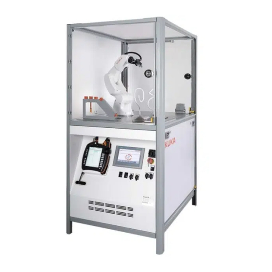
Description The ready2_educate_basic cell is used for teaching operator control and basic programming of KUKA robots. It contains ten cubes that can be used for programming simple pick-and-place tasks. Overview Fig. 3-1: Overview, ready2_educate_basic KR 3 R540 robot... -
Page 14: Control Panel
EMERGENCY STOP device and the “Ackn.” button for operator safety. Fig. 3-3: Control panel smartPAD Operator control and display elements 3.2.2.1 Operator control and display elements Fig. 3-4: Operator control and display elements 14/154 | www.kuka.com BA ready2_educate V8 | Issued: 05.09.2018... -
Page 15: Gripper System
The shut-off valve is used for locking and unlocking the service unit. The pneumatic system mounting plate may vary according to the ready2_educate variant. Setting: • Operating pressure: 6 bar BA ready2_educate V8 | Issued: 05.09.2018 www.kuka.com | 15/154... -
Page 16: Mounting Plate, Electrical System
Solenoid valve Service unit Pressure gauge Filter unit Condensate drainage screw 3.2.5 Mounting plate, electrical system Fig. 3-7: Mounting plate, electrical system Item Description Power supply, 200-240V, 50-60Hz F1.5.1 Fuse, 4A 16/154 | www.kuka.com BA ready2_educate V8 | Issued: 05.09.2018... -
Page 17: Ready2_Educate_Pro
Connections for gripper pressure valve, E-STOP, acknowledg- ing operator safety, safety switches, Profinet ready2_educate_pro Description The ready2_educate_pro cell is used for teaching advanced programming of KUKA robots using an application. Overview Fig. 3-8: Overview, ready2_educate_pro KR 3 R540 robot Mounting plate for control elements... -
Page 18: Control Panel
EMERGENCY STOP device and the “Ackn.” button for operator safety. Fig. 3-10: Control panel smartPAD Operator control and display elements 3.3.2.1 Operator control and display elements Fig. 3-11: Operator control and display elements 18/154 | www.kuka.com BA ready2_educate V8 | Issued: 05.09.2018... -
Page 19: Gripper System
Fig. 3-12: 2-jaw parallel gripper Energy supply system Gripper holder 2-jaw parallel gripper 3.3.4 Application components Description The gripper is used to grip the various components and set them down in new positions. BA ready2_educate V8 | Issued: 05.09.2018 www.kuka.com | 19/154... -
Page 20: Mounting Plate, Pneumatic System
The shut-off valve is used for locking and unlocking the service unit. The pneumatic system mounting plate may vary according to the ready2_educate variant. Setting: • Operating pressure: 6 bar 20/154 | www.kuka.com BA ready2_educate V8 | Issued: 05.09.2018... -
Page 21: Mounting Plate, Electrical System
Solenoid valve Service unit Pressure gauge Filter unit Condensate drainage screw 3.3.6 Mounting plate, electrical system Fig. 3-15: Mounting plate, electrical system Item Description Power supply, 200-240V, 50-60Hz F1.5.1 Fuse, 4A BA ready2_educate V8 | Issued: 05.09.2018 www.kuka.com | 21/154... -
Page 22: Ready2_Educate_Advanced
Connections for gripper pressure valve, E-STOP, acknowledg- ing operator safety, safety switches, Profinet ready2_educate_advanced Description The ready2_educate_advanced cell is used for teaching advanced pro- gramming of KUKA robots. Overview Fig. 3-16: Overview, ready2_educate_advanced KR 3 R540 robot Mounting plate for control elements... -
Page 23: Control Panel
The control panel contains the display and operator control elements, the EMERGENCY STOP safety system and operator safety for operation of the training cell. Fig. 3-18: Control panel smartPAD Operator control and display elements BA ready2_educate V8 | Issued: 05.09.2018 www.kuka.com | 23/154... -
Page 24: Operator Control And Display Elements
Acknowledge operator safety USB connection KSI connection Profinet connection Blanking cover 3.4.3 Gripper system Description The 2-jaw parallel gripper is used for gripping, positioning and setting down parts. Fig. 3-20: 2-jaw parallel gripper 24/154 | www.kuka.com BA ready2_educate V8 | Issued: 05.09.2018... -
Page 25: Application Components
The user-made application components may not have a drive of their own. In the case of user-made application components, the user is responsi- ble for reanalyzing the risk and hazard situation and implementing cor- responding safeguards. BA ready2_educate V8 | Issued: 05.09.2018 www.kuka.com | 25/154... -
Page 26: Mounting Plate, Pneumatic System
Setting: • Operating pressure: 6 bar Fig. 3-22: Mounting plate, pneumatic system Shut-off valve Pressure regulating valve Multiple distributor Solenoid valve Service unit Pressure gauge Filter unit Condensate drainage screw 26/154 | www.kuka.com BA ready2_educate V8 | Issued: 05.09.2018... -
Page 27: Mounting Plate, Electrical System
9 - 10 Not assigned 11 - 18 Digital outputs DO9 to DO16 19 -20 Not assigned 24V DC power supply Not assigned 23 - 24 0 V DC power supply Not assigned BA ready2_educate V8 | Issued: 05.09.2018 www.kuka.com | 27/154... -
Page 28: Cover
Female insert, PROFINET 24V DC power supply + I/O Guide bush 3.4.8 Cover Description The cover for protecting the interface when the media interface is not in use. Overview Fig. 3-25: Jumper plug 28/154 | www.kuka.com BA ready2_educate V8 | Issued: 05.09.2018... -
Page 29: Ready2_Educate_Pro_Vision
Description The ready2_educate_pro_vision cell is used for teaching advanced pro- gramming of KUKA robots using an application. Using the vision option, the position of a cube can be detected with a camera and the cube can then be gripped using a vacuum cup. -
Page 30: Control Panel
EMERGENCY STOP device and the “Ackn.” button for operator safety. Fig. 3-28: Control panel smartPAD Operator control and display elements 3.5.2.1 Operator control and display elements Fig. 3-29: Operator control and display elements 30/154 | www.kuka.com BA ready2_educate V8 | Issued: 05.09.2018... -
Page 31: Gripper System
Fig. 3-30: 2-jaw parallel gripper Energy supply system Gripper holder 2-jaw parallel gripper 3.5.4 Application components Description The gripper is used to grip the various components and set them down in new positions. BA ready2_educate V8 | Issued: 05.09.2018 www.kuka.com | 31/154... -
Page 32: Mounting Plate, Pneumatic System
The shut-off valve is used for locking and unlocking the service unit. The pneumatic system mounting plate may vary according to the ready2_educate variant. Setting: • Operating pressure: 6 bar 32/154 | www.kuka.com BA ready2_educate V8 | Issued: 05.09.2018... -
Page 33: Mounting Plate, Electrical System
Solenoid valve Service unit Pressure gauge Filter unit Condensate drainage screw 3.5.6 Mounting plate, electrical system Fig. 3-33: Mounting plate, electrical system Item Description Power supply, 200-240V, 50-60Hz F1.5.1 Fuse, 4A BA ready2_educate V8 | Issued: 05.09.2018 www.kuka.com | 33/154... -
Page 34: Vision
Using the ruler, the cube located at the edge of the chute can be tossed onto the mat. Another possibility is to set the cube down in a centering station and then take it to the magazine using the gripper. Overview Fig. 3-34: Vision 34/154 | www.kuka.com BA ready2_educate V8 | Issued: 05.09.2018... -
Page 35: Ejector / Mounting Plate, Electrical System
Description The ready2_educate_advanced_vision cell is used for teaching advanced programming of KUKA robots. Using the vision option, the position of a cube can be detected with a camera and the cube can then be gripped using a vacuum cup. -
Page 36: Kr C4 Compact Robot Controller
KR C4 compact robot controller Description The KR C4 compact robot controller is used for the robot. Further information is contained in the operating instructions for the ro- bot controller. Fig. 3-37: KR C4 compact 36/154 | www.kuka.com BA ready2_educate V8 | Issued: 05.09.2018... -
Page 37: Control Panel
The main switch is used to switch the cell on and off. If the main switch is turned off, the robot drives and the entire robot cell are switched off and all motions are stopped. EMERGENCY STOP device with key BA ready2_educate V8 | Issued: 05.09.2018 www.kuka.com | 37/154... -
Page 38: Gripper System
Fig. 3-40: 2-jaw parallel gripper Energy supply system Gripper holder 2-jaw parallel gripper 3.6.4 Application components Description The gripper is used to grip the various components and set them down in new positions. 38/154 | www.kuka.com BA ready2_educate V8 | Issued: 05.09.2018... -
Page 39: Mounting Plate, Pneumatic System
The shut-off valve is used for locking and unlocking the service unit. The pneumatic system mounting plate may vary according to the ready2_educate variant. Setting: • Operating pressure: 6 bar BA ready2_educate V8 | Issued: 05.09.2018 www.kuka.com | 39/154... -
Page 40: Mounting Plate, Electrical System
Pressure regulating valve Multiple distributor Solenoid valve Service unit Pressure gauge Filter unit Condensate drainage screw 3.6.6 Mounting plate, electrical system Fig. 3-43: Mounting plate, electrical system Item Description -A10 Switch CPU; PLC 40/154 | www.kuka.com BA ready2_educate V8 | Issued: 05.09.2018... -
Page 41: Media Interface
9 - 10 Not assigned 11 - 18 Digital outputs DO9 to DO16 19 -20 Not assigned 24V DC power supply Not assigned 23 - 24 0 V DC power supply Not assigned BA ready2_educate V8 | Issued: 05.09.2018 www.kuka.com | 41/154... -
Page 42: Cover
Female insert, PROFINET 24V DC power supply + I/O Guide bush 3.6.8 Cover Description The cover for protecting the interface when the media interface is not in use. Overview Fig. 3-45: Jumper plug 42/154 | www.kuka.com BA ready2_educate V8 | Issued: 05.09.2018... -
Page 43: Vision
Holder for vacuum cup Camera with lens Ruler with cube Spiral hose Calibration plate Cube with vacuum cup 3.6.10 Ejector / mounting plate, electrical system Description With the vision option, additional components are installed. BA ready2_educate V8 | Issued: 05.09.2018 www.kuka.com | 43/154... - Page 44 Overview Fig. 3-47: Ejector / mounting plate, electrical system -GS1 ejector -XOV 24 V power supply, PE connections -A11 switch vision 44/154 | www.kuka.com BA ready2_educate V8 | Issued: 05.09.2018...
-
Page 45: Technical Data
4.4.1 "Basic data, ready2_edu- cate_advanced" Page • Dimensions (>>> 4.3.2 "Dimensions, ready2_edu- cate_pro" Page • Pneumatic diagram (>>> 4.3.4 "Pneumatic diagram" Page • Load data (>>> 4.3.5 "Load data of gripper, ready2_educate_pro" Page BA ready2_educate V8 | Issued: 05.09.2018 www.kuka.com | 45/154... -
Page 46: Technical Data, Ready2_Educate_Basic
Technical data, ready2_educate_basic 4.2.1 Basic data, ready2_educate_basic Basic data Robot type KR 3 R540 Controller KR C4 compact Protection rating according to EN Robot controller 60529 • IP 20 Robot • IP 40 46/154 | www.kuka.com BA ready2_educate V8 | Issued: 05.09.2018... - Page 47 3k3 according to EN 60721-3-3; 1995 Altitude Without derating • up to 1000 m above mean sea level With derating 5%/1000 m • 1000 m … 4000 m above mean sea level BA ready2_educate V8 | Issued: 05.09.2018 www.kuka.com | 47/154...
-
Page 48: Dimensions, Ready2_Educate_Basic
Further information is contained in the operating and assembly instruc- tions for the manipulator. Further information is contained in the operating instructions for the ro- bot controller. 4.2.2 Dimensions, ready2_educate_basic Fig. 4-1: Dimensions, ready2_educate_basic 48/154 | www.kuka.com BA ready2_educate V8 | Issued: 05.09.2018... -
Page 49: Dimensions Of Gripper, Ready2_Educate_Basic
4.2.3 Dimensions of gripper, ready2_educate_basic Fig. 4-2: Dimensions BA ready2_educate V8 | Issued: 05.09.2018 www.kuka.com | 49/154... -
Page 50: Pneumatic Diagram
4.2.4 Pneumatic diagram Fig. 4-3: Pneumatic diagram, ready2_educate_basic 50/154 | www.kuka.com BA ready2_educate V8 | Issued: 05.09.2018... -
Page 51: Load Data Of Gripper, Ready2_Educate_Basic
With cube +38.3° 0° +103.3° 0° +30° 0° Fig. 4-5: TCP TCP of gripper Technical data, ready2_educate_pro 4.3.1 Basic data, ready2_educate_pro Basic data Robot type KR 3 R540 Controller KR C4 compact BA ready2_educate V8 | Issued: 05.09.2018 www.kuka.com | 51/154... - Page 52 Environmental conditions Operation +5 °C … +40 °C (278 K to 313 K) Temperature change max. 1.1 K/min Storage and transpor- -5 °C … +40 °C (268 K to 313 K) tation 52/154 | www.kuka.com BA ready2_educate V8 | Issued: 05.09.2018...
-
Page 53: Dimensions, Ready2_Educate_Pro
Further information is contained in the operating and assembly instruc- tions for the manipulator. Further information is contained in the operating instructions for the ro- bot controller. 4.3.2 Dimensions, ready2_educate_pro Fig. 4-6: Dimensions, ready2_educate_pro BA ready2_educate V8 | Issued: 05.09.2018 www.kuka.com | 53/154... -
Page 54: Dimensions Of Gripper, Ready2_Educate_Pro
4.3.3 Dimensions of gripper, ready2_educate_pro Fig. 4-7: Dimensions 54/154 | www.kuka.com BA ready2_educate V8 | Issued: 05.09.2018... -
Page 55: Pneumatic Diagram
4.3.4 Pneumatic diagram Fig. 4-8: Pneumatic diagram, ready2_educate_pro BA ready2_educate V8 | Issued: 05.09.2018 www.kuka.com | 55/154... -
Page 56: Load Data Of Gripper, Ready2_Educate_Pro
0.0028 0.0012 Lzc;kgm² 0.0004 0.0004 0.000491 0.000781 0.00058 Fig. 4-9: Gripper with and without a tool Without tool With cube With hook With pen +34.7 0 mm +109.3 0° +30° 0° 56/154 | www.kuka.com BA ready2_educate V8 | Issued: 05.09.2018... -
Page 57: Technical Data, Ready2_Educate_Advanced
420 kg Power supply connection Rated supply voltage AC 200V – 240V, single-phase, two-phase (with grounded neutral) (as symmetrical as possible) between the pha- ses used Permissible tolerance ±10% of rated voltage BA ready2_educate V8 | Issued: 05.09.2018 www.kuka.com | 57/154... - Page 58 Half-sine/11 ms in X/Y/Z direction) Further information is contained in the operating and assembly instruc- tions for the manipulator. Further information is contained in the operating instructions for the ro- bot controller. 58/154 | www.kuka.com BA ready2_educate V8 | Issued: 05.09.2018...
-
Page 59: Dimensions, Ready2_Educate_Advanced
4.4.2 Dimensions, ready2_educate_advanced Fig. 4-11: Dimensions, ready2_educate_advanced 4.4.3 Dimensions of gripper, ready2_educate_advanced Fig. 4-12: Dimensions BA ready2_educate V8 | Issued: 05.09.2018 www.kuka.com | 59/154... -
Page 60: Pneumatic Diagram
4.4.4 Pneumatic diagram Fig. 4-13: Pneumatic diagram, ready2_educate_advanced 60/154 | www.kuka.com BA ready2_educate V8 | Issued: 05.09.2018... -
Page 61: Load Data Of Gripper, Ready2_Educate_Advanced
0.0028 0.0012 Lzc;kgm² 0.0004 0.0004 0.000491 0.000781 0.00058 Fig. 4-14: Gripper with and without a tool Without tool With cube With hook With pen +34.7 0 mm +109.3 0° +30° 0° BA ready2_educate V8 | Issued: 05.09.2018 www.kuka.com | 61/154... -
Page 62: Technical Data, Ready2_Educate_Pro_Vision
430 kg Power supply connection Rated supply voltage AC 200V – 240V, single-phase, two-phase (with grounded neutral) (as symmetrical as possible) between the pha- ses used Permissible tolerance ±10% of rated voltage 62/154 | www.kuka.com BA ready2_educate V8 | Issued: 05.09.2018... - Page 63 Half-sine/11 ms in X/Y/Z direction) Further information is contained in the operating and assembly instruc- tions for the manipulator. Further information is contained in the operating instructions for the ro- bot controller. BA ready2_educate V8 | Issued: 05.09.2018 www.kuka.com | 63/154...
-
Page 64: Dimensions, Ready2_Educate_Pro_Vision
4.5.2 Dimensions, ready2_educate_pro_vision Fig. 4-16: Dimensions, ready2_educate_pro 4.5.3 Dimensions of gripper, ready2_educate_pro_vision Fig. 4-17: Dimensions 64/154 | www.kuka.com BA ready2_educate V8 | Issued: 05.09.2018... -
Page 65: Pneumatic Diagram
0.661 kg 0.679 kg 0.697 kg 0.828 kg Lx;mm 12.18 12.76 14.45 21.92 17.47 Ly;mm 2.33 2.27 1.86 1.99 Lz;mm 48.63 50.2 53.66 69.86 56.31 Lxc;kgm² 0.0009 0.00098 0.0013 0.0026 0.0012 BA ready2_educate V8 | Issued: 05.09.2018 www.kuka.com | 65/154... - Page 66 0.000781 0.00058 Fig. 4-19: Gripper with and without a tool Without tool With cube With hook With pen +34.7 0 mm +109.3 0° +30° 0° Fig. 4-20: TCP TCP of gripper 66/154 | www.kuka.com BA ready2_educate V8 | Issued: 05.09.2018...
-
Page 67: Technical Data, Ready2_Educate_Advanced_Vision
Air connection Air connection Compressed air, oil-free: dry; filtered (max. particle size 0.01 mm); min. operating pressure 6 bar BA ready2_educate V8 | Issued: 05.09.2018 www.kuka.com | 67/154... - Page 68 Half-sine/11 ms in X/Y/Z direction) Further information is contained in the operating and assembly instruc- tions for the manipulator. Further information is contained in the operating instructions for the ro- bot controller. 68/154 | www.kuka.com BA ready2_educate V8 | Issued: 05.09.2018...
-
Page 69: Dimensions, Ready2_Educate_Advanced_Vision
4.6.2 Dimensions, ready2_educate_advanced_vision Fig. 4-21: Dimensions, ready2_educate_advanced BA ready2_educate V8 | Issued: 05.09.2018 www.kuka.com | 69/154... -
Page 70: Pneumatic Diagram
0.661 kg 0.679 kg 0.697 kg 0.828 kg Lx;mm 12.18 12.76 14.45 21.92 17.47 Ly;mm 2.33 2.27 1.86 1.99 Lz;mm 48.63 50.2 53.66 69.86 56.31 Lxc;kgm² 0.0009 0.00098 0.0013 0.0026 0.0012 70/154 | www.kuka.com BA ready2_educate V8 | Issued: 05.09.2018... - Page 71 0.000781 0.00058 Fig. 4-23: Gripper with and without a tool Without tool With cube With hook With pen +34.7 0 mm +109.3 0° +30° 0° Fig. 4-24: TCP TCP of gripper BA ready2_educate V8 | Issued: 05.09.2018 www.kuka.com | 71/154...
-
Page 72: Plates And Labels
They must not be removed or rendered illegible. Illegible plates and labels must be replaced. Bulkhead-mounted housing Fig. 4-25: Plates and labels Item Description Description of fuses on the inside of the maintenance door for ready2_educate_basic and ready2_educate_pro. 72/154 | www.kuka.com BA ready2_educate V8 | Issued: 05.09.2018... - Page 73 Description of fuses on the inside of the maintenance door for ready2_educate_advanced. Identification plate Content according to Machinery Directive. Identification plate Content according to Machinery Directive. Warning Electrical hazard. Authorized personnel only. SCCR value: 5 kA BA ready2_educate V8 | Issued: 05.09.2018 www.kuka.com | 73/154...
- Page 74 Description Basic gripper serial number Crushing hazard Reaching into the gripper poses a crushing hazard. Do not reach into the gripper when the robot is in operation. Pro gripper serial number 74/154 | www.kuka.com BA ready2_educate V8 | Issued: 05.09.2018...
- Page 75 Item Description Crushing hazard Reaching into the gripper poses a crushing hazard. Do not reach into the gripper when the robot is in operation. BA ready2_educate V8 | Issued: 05.09.2018 www.kuka.com | 75/154...
-
Page 76: Safety
No modifications may be carried out to the training cell without the author- ization of KUKA Deutschland GmbH. Additional components (gripper jaws) not supplied by KUKA Deutschland GmbH may be integrated into the training cell. The user is liable for any damage these components may cause to the training cell or to other material property. -
Page 77: Intended Use
• The trainer must explain the operator control elements of the training cell to the training participants. Training participant The training participant must meet the following requirements: • The training participant must receive safety instruction and confirm this. BA ready2_educate V8 | Issued: 05.09.2018 www.kuka.com | 77/154... -
Page 78: Safety Functions
• Moving the robot in T2 mode with a safety door of the training cell open is not permitted. Close the safety door and acknowledge to continue. 78/154 | www.kuka.com BA ready2_educate V8 | Issued: 05.09.2018... -
Page 79: Main Switch On The Control Panel
The cell can be operated in the following modes: • Manual Reduced Velocity (T1) • Manual High Velocity (T2) • Automatic (AUT) The operating mode is selected using the mode selector switch on the smartPAD. BA ready2_educate V8 | Issued: 05.09.2018 www.kuka.com | 79/154... -
Page 80: Start-Up And Recommissioning
• EMERGENCY STOP device on the control panel • EMERGENCY STOP device on the smartPAD • Enabling device (in the test modes) • Operator safety (in the automatic modes) 80/154 | www.kuka.com BA ready2_educate V8 | Issued: 05.09.2018... -
Page 81: Maintenance And Repair
Faulty components must be replaced using new components with the same article numbers or equivalent components approved by KUKA Deutschland GmbH for this purpose. Cleaning and preventive maintenance work is to be carried out in accord- ance with the operating instructions. -
Page 82: Performance Level
Interlocking devices associated with guards - Principles for design and selection. EN ISO 14120:2015 Safety of machinery: Guards - General requirements for the design and construction of fixed and movable guards 82/154 | www.kuka.com BA ready2_educate V8 | Issued: 05.09.2018... - Page 83 Electrical equipment of machines - Part 1: General requirements EN 61000-6-2:2005 Electromagnetic compatibility (EMC): Part 6-2: Generic standards; Immunity for industrial environments EN 61000-6-4:2007 + Electromagnetic compatibility (EMC): A1:2011 Part 6-4: Generic standards; Emission standard for industrial envi- ronments BA ready2_educate V8 | Issued: 05.09.2018 www.kuka.com | 83/154...
-
Page 84: Planning
In order to assure the energy supply, depending on the country-specific variants, it may be necessary for the customer to connect a transformer in between. Fig. 6-1: Energy supply interface Power connection X00 Air connection 84/154 | www.kuka.com BA ready2_educate V8 | Issued: 05.09.2018... -
Page 85: Transportation
Procedure 1. Pull the lift doors downwards approx. 20 mm. 2. Screw 4 Allen screws with washers into the floor using a size 5 Allen key. BA ready2_educate V8 | Issued: 05.09.2018 www.kuka.com | 85/154... -
Page 86: Transport Packaging
2. Fasten both unattached side panels to the cell. 3. Attach the rear panel to the cell. 4. Attach the front panel using 6 screws. 5. Fasten the cover using 4 screws. Fig. 7-2: Transport packaging 86/154 | www.kuka.com BA ready2_educate V8 | Issued: 05.09.2018... -
Page 87: Transportation By Fork Lift Truck
The ready2_educate cell must not be damaged when moving the pallet truck into position. CAUTION The training cell may only be transported in the vertical position. Dam- age to property may otherwise result. BA ready2_educate V8 | Issued: 05.09.2018 www.kuka.com | 87/154... - Page 88 7. Secure the safety door so that it cannot open on its own. 8. Carry out a visual inspection before transportation. 9. Carefully pick up the ready2_educate cell with the pallet truck and transport it away. Fig. 7-4: Transportation by pallet truck 88/154 | www.kuka.com BA ready2_educate V8 | Issued: 05.09.2018...
-
Page 89: Start-Up And Recommissioning
PE bag. Fig. 8-2 Installing the ready2_educate cell Precondition • The installation site is sufficiently lit. • The installation site is free from excessive dirt and humidity. BA ready2_educate V8 | Issued: 05.09.2018 www.kuka.com | 89/154... -
Page 90: Connecting The Ready2_Educate Cell
Fig. 8-3: Energy supply interface Power connection X00 Air connection 3. Pull the cable from the smartPAD through the cable guide and connect it to the robot controller at interface X19. 90/154 | www.kuka.com BA ready2_educate V8 | Issued: 05.09.2018... -
Page 91: Switching On The Cell
EMERGENCY STOP device and store the key for the EMERGENCY STOP securely. Information about operator control of the robot using the smartPAD can be found in the operating and programming instructions for the KUKA System Software (KSS). Restarting operation following an EMERGENCY STOP... -
Page 92: Removing/Attaching The Detachable Doors
4. After the maintenance work on the robot controller, reattach the de- tachable doors. 5. Unscrew the knurled screws. 6. Insert the plugs into the holes of the knurled screws. 7. Close the detachable doors. 92/154 | www.kuka.com BA ready2_educate V8 | Issued: 05.09.2018... -
Page 93: Installation
System requirements, ready2_educate Hardware • KR C4 compact Software • KUKA System Software 8.3.x • GripperSpotTech 4.0.x • WorkVisual 4.0.x The number of the required release must be taken from the file Release- Notes_[…].txt. The file is located on the data storage medium with the rel- evant software. - Page 94 8. Once this file is loaded, the project can be transferred to the controller. 9. Confirm the changes with Yes. The robot controller carries out a re- boot. Information about procedures in WorkVisual is contained in the WorkVi- sual documentation. 94/154 | www.kuka.com BA ready2_educate V8 | Issued: 05.09.2018...
-
Page 95: Uninstalling Ready2_Educate
LOG file A LOG file is created under C:\KRC\ROBOTER\LOG. Installation, ready2_educate_advanced 9.2.1 System requirements, ready2_educate_advanced Hardware • KR C4 compact Software • KUKA System Software 8.3.x • GripperSpotTech 4.0.x • WorkVisual 4.0.x BA ready2_educate V8 | Issued: 05.09.2018 www.kuka.com | 95/154... -
Page 96: Installing Or Updating Ready2_Educate_Advanced
6. Once this file is loaded, the project can be transferred to the controller. 7. Confirm the changes with Yes. The robot controller carries out a re- boot. Information about procedures in WorkVisual is contained in the WorkVi- sual documentation. 96/154 | www.kuka.com BA ready2_educate V8 | Issued: 05.09.2018... -
Page 97: Uninstalling Ready2_Educate_Advanced
9.3.1 System requirements, ready2_educate_vision Hardware • KR C4 compact Software • KUKA System Software 8.3.x • GripperSpotTech 4.0.x • WorkVisual 4.0.x • ready2_educate • VisionTech 4.0.x The number of the required release must be taken from the file Release- Notes_[…].txt. -
Page 98: Installing Or Updating Ready2_Educate_Vision
Click on the Data and Icons tab. The configuration can be loaded here. c. The configuration file GripperEjektorConfig.xml for the gripper al- location is located in the DOC directory of the KOP file. The gripper and ejector are now configured. 98/154 | www.kuka.com BA ready2_educate V8 | Issued: 05.09.2018... -
Page 99: Uninstalling Ready2_Educate_Vision
Answer this with Yes. The option package is uninstalled and the robot controller carries out a reboot. Information about procedures in WorkVisual is contained in the WorkVi- sual documentation. LOG file A LOG file is created under C:\KRC\ROBOTER\LOG. BA ready2_educate V8 | Issued: 05.09.2018 www.kuka.com | 99/154... -
Page 100: Operation
The smartPAD has a touch screen: the smartHMI can be operated with a finger or stylus. An external mouse or external keyboard is not necessary. Overview Fig. 10-1: KUKA smartPAD, front view Item Description Button for disconnecting the smartPAD Mode selector switch. - Page 101 Displays the keyboard. It is generally not necessary to press this key to display the keyboard, as the smartHMI detects when keyboard input is required and displays the keyboard au- tomatically. BA ready2_educate V8 | Issued: 05.09.2018 www.kuka.com | 101/154...
-
Page 102: Rear View
10.1.2 Rear view Overview Fig. 10-2: KUKA smartPAD, rear view Enabling switch USB connection Start key (green) Enabling switch Enabling switch Identification plate Description Element Description Rating plate Rating plate Start key The Start key is used to start a program. -
Page 103: Status Keys
Close the gripper with this key. Gripper 2: ejector Only for ready2_educate_pro_vision and ready2_educate_advanced_vision Vacuum ON Only for ready2_educate_pro_vision and ready2_educate_advanced_vision Blast air ON Only for ready2_educate_pro_vision and ready2_educate_advanced_vision OFF state Only for ready2_educate_pro_vision and ready2_educate_advanced_vision BA ready2_educate V8 | Issued: 05.09.2018 www.kuka.com | 103/154... -
Page 104: Operator Control Via Touch Panel
Start menu user interface Automatic External inputs user interface Automatic External outputs user interface Analog I/O robot user interface Training I/O robot user interface Messages user interface Select language START EXT button 104/154 | www.kuka.com BA ready2_educate V8 | Issued: 05.09.2018... - Page 105 The status of the outputs can be read and set in the Automatic External outputs user interface. • Red: output is not set • Green: output is set The status of the output can be changed by tapping on the slide switch. BA ready2_educate V8 | Issued: 05.09.2018 www.kuka.com | 105/154...
- Page 106 The trainers can read and set the inputs and outputs accordingly in the Training I/O robot user interface. Names can be assigned to the inputs and outputs by tapping on the corresponding fields. 106/154 | www.kuka.com BA ready2_educate V8 | Issued: 05.09.2018...
- Page 107 Fig. 10-8: Messages user interface NOTICE If the operator leaves the training cell, he must lock the touch panel, actuate the EMERGENCY STOP device and store the key for the EMERGENCY STOP securely. BA ready2_educate V8 | Issued: 05.09.2018 www.kuka.com | 107/154...
-
Page 108: Configuration
$IN[110] $MOVE_ENABLE 17.2 $IN[111] $CONF_MESS 17.3 $IN[112] $DRIVE_OFF 17.4 $IN[113] $DRIVE_ON 17.5 $IN[114] $I_O_ACT 17.6 $IN[115] 17.7 $IN[116] EXT_START 18.0 $ANIN[1] Analog input $IN[200] User-defined bit00 30.4 $IN[201] User-defined bit01 30.5 108/154 | www.kuka.com BA ready2_educate V8 | Issued: 05.09.2018... - Page 109 29.5 $OUT[202] User-defined bit 02 29.6 $OUT[203] User-defined bit 03 29.7 $OUT[204] User-defined bit 04 30.0 $OUT[205] User-defined bit 05 30.1 $OUT[206] User-defined bit 06 30.2 $OUT[207] User-defined bit 07 30.3 BA ready2_educate V8 | Issued: 05.09.2018 www.kuka.com | 109/154...
-
Page 110: I/Os For Control, Ready2_Educate_Vision
Ejector - Vac- ponent picked uum ON $IN[6] Ejector - Com- $OUT[6] Ejector - Blast ponent picked air ON $IN[7] Gripper open $OUT[7] Open gripper $IN[8] Gripper closed $OUT[8] Close gripper 110/154 | www.kuka.com BA ready2_educate V8 | Issued: 05.09.2018... -
Page 111: Programming
Programming Information about programming the robot is contained in the operating and programming instructions for the KUKA System Software. Information about programming the gripper can be found in the operat- ing and programming instructions for GripperSpotTech. 12.1 Inline forms – overview... -
Page 112: Gripper Syn Set Inline Form
The time specification is absolute. The switching point varies according to the velocity of the robot. 12.1.3 Gripper CHECK inline form The switching state of the gripper is checked via the inline form. 112/154 | www.kuka.com BA ready2_educate V8 | Issued: 05.09.2018... -
Page 113: Gripper Syn Check Inline Form
The number and the designation of switching states that can be selected depends on the configuration. Point to which Gripper SYN CHECK refers • START: Start point of the motion • END: End point of the motion BA ready2_educate V8 | Issued: 05.09.2018 www.kuka.com | 113/154... - Page 114 If a state does not exist, an appropriate error strategy can be set. • No Check: The program is continued without checking whether the switching state exists. • Strategy 1…3: Configured error strategies 114/154 | www.kuka.com BA ready2_educate V8 | Issued: 05.09.2018...
-
Page 115: Maintenance
(maintenance intervals, activities). The maintenance intervals given in the table are valid for the operating conditions specified in the technical data. KUKA Deutschland GmbH must be consulted in the case of discrepancies! Information about maintenance of the robot and robot controller is con- tained in the robot operating instructions and in the robot controller op- erating instructions. -
Page 116: Drainage Of Condensate On The Compressed Air Service Unit
• Check the components and surfaces for external damage. • Check the steel components for traces of corrosion. If necessary, repair damage. We recommend having annual maintenance performed by KUKA Serv- ice. For purposes of maintenance on the robot controller, the detachable doors can be removed. - Page 117 4. Only clean polycarbonate surfaces with a gentle cleaning agent. 5. Replace damaged or missing inscriptions, labels and plates. Detailed information about the individual components is contained in the manufacturer’s documentation. BA ready2_educate V8 | Issued: 05.09.2018 www.kuka.com | 117/154...
-
Page 118: Repair
14.4.4 "Exchanging the blade-type fuse" Page 126) • Exchanging the gripper cable (>>> 14.4.5 "Exchanging the gripper cable" Page 126) • Exchanging the switch (Vision) (>>> 14.4.6 "Exchanging the switch" Page 127) 118/154 | www.kuka.com BA ready2_educate V8 | Issued: 05.09.2018... -
Page 119: Repair, Ready2_Educate_Basic
• The robot is depressurized. Procedure 1. Disconnect the pneumatic line at the push-in coupling. 2. Remove the gripper cables. 3. Mark the position of the proximity switches. 4. Unplug the proximity switches. BA ready2_educate V8 | Issued: 05.09.2018 www.kuka.com | 119/154... -
Page 120: Installing The Basic Gripper
2. Connect the pneumatic line at the push-in coupling. 3. Connect the proximity switches at the markings. 4. Check the function and position (I/O) of the proximity switches on the smartPAD. 120/154 | www.kuka.com BA ready2_educate V8 | Issued: 05.09.2018... -
Page 121: Exchanging Safety Door Switches
2. Remove 4 TX-M4x20 Torx safety screws from each safety door switch. 3. Remove the old safety door switch. 4. Fasten each new safety door switch with 4 TX-M4x20-A4-80 Torx safety screws. 5. Install the cables. 6. Carry out a function test. BA ready2_educate V8 | Issued: 05.09.2018 www.kuka.com | 121/154... -
Page 122: Exchanging The Proximity Switches On The Gripper
Fig. 14-5: Exchanging proximity switches Proximity switches Plug connection 14.3.4 Exchanging the blade-type fuse Precondition • The robot controller is switched off and secured to prevent unauthor- ized persons from switching it on again. 122/154 | www.kuka.com BA ready2_educate V8 | Issued: 05.09.2018... -
Page 123: Repair, Ready2_Educate_Pro
2. Remove the gripper cables. 3. Mark the position of the proximity switches. 4. Unplug the proximity switches. 5. Remove 4 M5x16-8.8 Allen screws with washers from the gripper holder (gripper side). BA ready2_educate V8 | Issued: 05.09.2018 www.kuka.com | 123/154... -
Page 124: Installing The Pro Gripper
1. Fasten the gripper by means of 4 M5x16-8.8 Allen screws with wash- ers to the gripper holder (gripper side). 2. Connect the pneumatic lines. 3. Connect the gripper cables. Fig. 14-8: Exchanging the gripper 124/154 | www.kuka.com BA ready2_educate V8 | Issued: 05.09.2018... -
Page 125: Exchanging Safety Door Switches
5. Plug in new proximity switches. Pay attention to the markings. 6. Plug the cables of the proximity switches and the plug connection to- gether. 7. Fasten the cables of the proximity switches using a cable strap. BA ready2_educate V8 | Issued: 05.09.2018 www.kuka.com | 125/154... -
Page 126: Exchanging The Blade-Type Fuse
• The robot controller is switched off and secured to prevent unauthor- ized persons from switching it on again. Procedure 1. Detach the plug connection at the rear of the gripper. 126/154 | www.kuka.com BA ready2_educate V8 | Issued: 05.09.2018... -
Page 127: Exchanging The Switch
Procedure 1. Unplug the cables connected to the switch. 2. Remove the switch. 3. Attach the new switch. 4. Connect the cables to the switch. BA ready2_educate V8 | Issued: 05.09.2018 www.kuka.com | 127/154... -
Page 128: Exchanging The Suction Gripper
3. Fasten the new camera with 2 M3x6-8.8 screws. 4. Plug in the cable. 14.5 Repair, ready2_educate_advanced 14.5.1 Gripper change, ready2_educate_advanced 14.5.1.1 Removing the gripper Precondition • The robot is depressurized. 128/154 | www.kuka.com BA ready2_educate V8 | Issued: 05.09.2018... -
Page 129: Installing The Gripper
Procedure 1. Fasten the gripper by means of 4 M5x16-8.8 Allen screws with wash- ers to the gripper holder (gripper side). 2. Connect the pneumatic lines. 3. Connect the gripper cables. BA ready2_educate V8 | Issued: 05.09.2018 www.kuka.com | 129/154... -
Page 130: Exchanging Safety Door Switches
3. Remove the old safety door switch. 4. Fasten each new safety door switch with 4 TX-M4x20-A4-80 Torx safety screws. 5. Install the cables. 6. Carry out a function test. Fig. 14-17: Exchanging a safety door switch 130/154 | www.kuka.com BA ready2_educate V8 | Issued: 05.09.2018... -
Page 131: Exchanging The Touch Panel
6. Plug the cables of the proximity switches and the plug connection to- gether. 7. Fasten the cables of the proximity switches using a cable strap. Fig. 14-18: Exchanging proximity switches Proximity switches Plug connection BA ready2_educate V8 | Issued: 05.09.2018 www.kuka.com | 131/154... -
Page 132: Exchanging The Blade-Type Fuse
• The robot controller is switched off and secured to prevent unauthor- ized persons from switching it on again. Procedure 1. Detach the plug connection at the rear of the gripper. Fig. 14-20: Detaching the plug connection Plug connection 132/154 | www.kuka.com BA ready2_educate V8 | Issued: 05.09.2018... -
Page 133: Exchanging The Cpu
Procedure 1. Unplug the cables connected to the CPU. 2. Remove the CPU. 3. Fit the new CPU. 4. Connect the cables to the CPU. Fig. 14-22: Exchanging the CPU BA ready2_educate V8 | Issued: 05.09.2018 www.kuka.com | 133/154... -
Page 134: Exchanging The Simatic Bus Adapter
Procedure 1. Unplug the cables connected to the switch. 2. Remove the switch. 3. Attach the new switch. 4. Connect the cables to the switch. Fig. 14-24: Exchanging the switch 134/154 | www.kuka.com BA ready2_educate V8 | Issued: 05.09.2018... -
Page 135: Exchanging The Suction Gripper
Procedure 1. Unplug the cable. 2. Remove 2 M3x6-8.8 screws from the camera. 3. Fasten the new camera with 2 M3x6-8.8 screws. 4. Plug in the cable. BA ready2_educate V8 | Issued: 05.09.2018 www.kuka.com | 135/154... -
Page 136: Decommissioning, Storage And Disposal
Procedure 1. Exit the programming exercise correctly. 2. Turn off the main switch of the robot controller. Further information is contained in the operating and programming in- structions for the KUKA System Software (KSS). 15.1.2 Decommissioning Precondition • Observe the ESD guidelines. -
Page 137: Disposal
Information about disposing of the robot and robot controller can be found in the operating or assembly instructions of the robot and in the operating or assembly instructions of the robot controller. BA ready2_educate V8 | Issued: 05.09.2018 www.kuka.com | 137/154... -
Page 138: Appendix
00-308-726 Camera 00-284-176 Lens 00-206-197 Switch 5xRJ45 1xSFP PoE GigE 00-219-506 CPU 1512SP 1 PN FOR ET 200SP 00-315-007 SIMATIC BUS ADAPTER BA 2XRJ45 00-241-983 Ethernet Switch RJ45 eCon 2050 00-188-785 138/154 | www.kuka.com BA ready2_educate V8 | Issued: 05.09.2018... -
Page 139: Tightening Torques
Tighten M5 domed cap nuts with a torque of 4.2 Nm. 16.3 EU Declaration of Conformity according to EC Machinery Directive 2006/42/EC, Annex II A The manufacturer / company placing the product on the market: KUKA Deutschland GmbH BA ready2_educate V8 | Issued: 05.09.2018 www.kuka.com | 139/154... -
Page 140: 2006/42/Ec, Annex Ii A
• EN 60204-1:2006+A1:2009 • EN 61000-6-2:2005 • EN 61000-6-4:2007+A1:2011 Authorized representative for the compilation of the technical documenta- tion: KUKA Aktiengesellschaft, CLD-PC Zugspitzstrasse 140, D-86165 Augsburg, Germany 16.4 EU Declaration of Conformity according to EC Machinery Directive 2006/42/EC, Annex II A... -
Page 141: Eu Declaration Of Conformity According To Ec Machinery Directive 2006/42/Ec, Annex Ii A
• EN 60204-1:2006+A1:2009 • EN 61000-6-2:2005 • EN 61000-6-4:2007+A1:2011 Authorized representative for the compilation of the technical documenta- tion: KUKA Aktiengesellschaft, CLD-PC Zugspitzstrasse 140, D-86165 Augsburg, Germany 16.5 EU Declaration of Conformity according to EC Machinery Directive 2006/42/EC, Annex II A... -
Page 142: Eu Declaration Of Conformity According To Ec Machinery Directive 2006/42/Ec, Annex Ii A
• EN 60204-1:2006+A1:2009 • EN 61000-6-2:2005 • EN 61000-6-4:2007+A1:2011 Authorized representative for the compilation of the technical documenta- tion: KUKA Aktiengesellschaft, CLD-PC Zugspitzstrasse 140, D-86165 Augsburg, Germany 16.7 EU Declaration of Conformity according to EC Machinery Directive 2006/42/EC, Annex II A... - Page 143 • EN 61000-6-2:2005 • EN 61000-6-4:2007+A1:2011 Authorized representative for the compilation of the technical documenta- tion: KUKA Aktiengesellschaft, CLD-PC Zugspitzstrasse 140, D-86165 Augsburg, Germany BA ready2_educate V8 | Issued: 05.09.2018 www.kuka.com | 143/154...
-
Page 144: Kuka Service
‒ Diagnostic package KRCDiag Additionally for KUKA Sunrise: Existing projects including applica- tions For versions of KUKA System Software older than V8: Archive of the software (KRCDiag is not yet available here.) ‒ Application used ‒ External axes used 17.2... - Page 145 Australia KUKA Robotics Australia Pty Ltd 45 Fennell Street Port Melbourne VIC 3207 Australia Tel. +61 3 9939 9656 info@kuka-robotics.com.au www.kuka-robotics.com.au Belgium KUKA Automatisering + Robots N.V. Centrum Zuid 1031 3530 Houthalen Belgium Tel. +32 11 516160 Fax +32 11 526794 info@kuka.be...
- Page 146 Zugspitzstr. 140 86165 Augsburg Germany Tel. +49 821 797-1926 Fax +49 821 797-41 1926 Hotline.robotics.de@kuka.com www.kuka.com France KUKA Automatisme + Robotique SAS Techvallée 6, Avenue du Parc 91140 Villebon S/Yvette France Tel. +33 1 6931660-0 Fax +33 1 6931660-1 commercial@kuka.fr www.kuka.fr...
- Page 147 Ansan City, Gyeonggi Do 426-901 Korea Tel. +82 31 501-1451 Fax +82 31 501-1461 info@kukakorea.com Malaysia KUKA Robot Automation (M) Sdn Bhd South East Asia Regional Office No. 7, Jalan TPP 6/6 Taman Perindustrian Puchong 47100 Puchong Selangor Malaysia Tel. +60 (03) 8063-1792 Fax +60 (03) 8060-7386 info@kuka.com.my...
- Page 148 Mexico KUKA de México S. de R.L. de C.V. Progreso #8 Col. Centro Industrial Puente de Vigas Tlalnepantla de Baz 54020 Estado de México Mexico Tel. +52 55 5203-8407 Fax +52 55 5203-8148 info@kuka.com.mx www.kuka-robotics.com/mexico Norway KUKA Sveiseanlegg + Roboter...
- Page 149 KUKA Russia OOO 1-y Nagatinskiy pr-d, 2 117105 Moskau Russia Tel. +7 495 665-6241 support.robotics.ru@kuka.com Sweden KUKA Svetsanläggningar + Robotar AB A. Odhners gata 15 421 30 Västra Frölunda Sweden Tel. +46 31 7266-200 Fax +46 31 7266-201 info@kuka.se Switzerland...
- Page 150 South Africa Tel. +27 41 391 4700 Fax +27 41 373 3869 www.jendamark.co.za Taiwan KUKA Automation Taiwan Co. Ltd. 1F, No. 298 Yangguang ST., Nei Hu Dist., Taipei City, Taiwan 114 Taiwan Tel. +886 2 8978 1188 Fax +886 2 8797 5118 info@kuka.com.tw...
- Page 151 51870 Shelby Parkway Shelby Township 48315-1787 Michigan Tel. +1 866 873-5852 Fax +1 866 329-5852 info@kukarobotics.com www.kukarobotics.com KUKA Robotics UK Ltd Great Western Street Wednesbury West Midlands WS10 7LL Tel. +44 121 505 9970 Fax +44 121 505 6589 service@kuka-robotics.co.uk www.kuka-robotics.co.uk BA ready2_educate V8 | Issued: 05.09.2018...
-
Page 152: Index
Installing ready2_educate_advanced..... 96 Dimensions, ready2_educate_pro....53 Installing ready2_educate_vision....98 Dimensions, ready2_educate_pro_vision..64 Installing transport safeguard......85 Disposal..........81, 136 Intended use..........10, 77 Drainage of condensate....... 116 Introduction............8 EC declaration of conformity......76 Jog keys............101 152/154 | www.kuka.com BA ready2_educate V8 | Issued: 05.09.2018... - Page 153 Keyboard key..........101 ready2_educate cell, switching off....136 KOP..............9 ready2_educate, cleaning......116 KSS..............9 Recommissioning........80, 89 KUKA Customer Support......144 Relative air humidity..... 47, 53, 58, 63, 68 KUKA Service..........144 Repair............. 81, 118 KUKA smartPAD...........100 Restarting operation following an EMERGEN- CY STOP............91 Robot type......
- Page 154 Uninstalling ready2_educate_vision....99 Updating ready2_educate......93 Updating ready2_educate_advanced.....96 Updating ready2_educate_vision....98 USB connection..........102 Use, contrary to intended use....... 76 Use, improper..........76 Vibration resistance....48, 53, 58, 63, 68 Vision............34, 43 Warnings............8 154/154 | www.kuka.com BA ready2_educate V8 | Issued: 05.09.2018...
Need help?
Do you have a question about the ready2 educate and is the answer not in the manual?
Questions and answers