
Related Manuals for Kuka KR 20-3


Summary of Contents for Kuka KR 20-3
- Page 1 KUKA Roboter GmbH Robots KR 20-3 With C Variants Specification KR 20-3 Issued: 22.04.2016 Version: Spez KR 20-3 V2...
- Page 2 Subject to technical alterations without an effect on the function. Translation of the original documentation KIM-PS5-DOC Publication: Pub Spez KR 20-3 (PDF) en Book structure: Spez KR 20-3 V2.1 Version: Spez KR 20-3 V2 Issued: 22.04.2016 Version: Spez KR 20-3 V2 2 / 81...
-
Page 3: Table Of Contents
Basic data, KR 20-3 C ..................4.3.2 Axis data, KR 20-3 C .................... 4.3.3 Payloads, KR 20-3 C .................... 4.3.4 Loads acting on the foundation, KR 20-3 C ............Supplementary load ....................Plates and labels ......................Stopping distances and times ..................4.6.1 General information .................... - Page 4 Transporting the robot ....................Options ......................Working range limitation, supplementary stop (optional) ........... Energy supply systems (optional) ................KUKA Service ....................Requesting support ....................KUKA Customer Support ................... Index ......................Issued: 22.04.2016 Version: Spez KR 20-3 V2 4 / 81...
-
Page 5: Introduction
Procedures marked with this warning must be followed exactly. These notices serve to make your work easier or contain references to further Notices information. Tip to make your work easier or reference to further information. Issued: 22.04.2016 Version: Spez KR 20-3 V2 5 / 81... - Page 6 KR 20-3 Issued: 22.04.2016 Version: Spez KR 20-3 V2 6 / 81...
-
Page 7: Purpose
For optimal use of our products, we recommend that our customers take part in a course of training at KUKA College. Information about the training program can be found at www.kuka.com or can be ob- tained directly from our subsidiaries. - Page 8 KR 20-3 Issued: 22.04.2016 Version: Spez KR 20-3 V2 8 / 81...
-
Page 9: Product Description
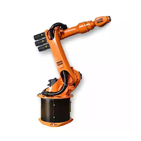
Description of the manipulator The manipulators (manipulator = robot arm and electrical installations) Overview (>>> Fig. 3-2 ) of the KR 20-3 model are designed as 6-axis jointed-arm kine- matic systems. They consist of the following principal components: In-line wrist ... - Page 10 The base frame is the base of the robot. It is screwed to the mounting base. Base frame The flexible tube for the electrical installations is installed in the base frame. Issued: 22.04.2016 Version: Spez KR 20-3 V2 10 / 81...
- Page 11 1 to 3, energy supply systems for axes 3 to 6, or working range limitation systems for A1. The options are described in separate docu- mentation. Issued: 22.04.2016 Version: Spez KR 20-3 V2 11 / 81...
- Page 12 KR 20-3 Issued: 22.04.2016 Version: Spez KR 20-3 V2 12 / 81...
-
Page 13: Technical Data
(>>> 4.5 "Plates and labels" Page 27) Stopping distances and times (>>> 4.6.4 "Stopping distances and times, KR 20-3 C" Page 36) Technical data, KR 20-3 4.2.1 Basic data, KR 20-3 Basic data KR 20-3 Number of axes... -
Page 14: Axis Data, Kr 20-3
156 °/s 156 °/s 156 °/s 330 °/s 332 °/s 616 °/s The direction of motion and the arrangement of the individual axes may be not- ed from the following diagram. Issued: 22.04.2016 Version: Spez KR 20-3 V2 14 / 81... - Page 15 The following diagrams show the shape and size of the working envelope for Working these variants of this product family. envelope The reference point for the working envelope is the intersection of axes 4 and Issued: 22.04.2016 Version: Spez KR 20-3 V2 15 / 81...
- Page 16 KR 20-3 Fig. 4-2: Work envelope, side view, KR 20-3 Fig. 4-3: Work envelope, top view, KR 20-3 Issued: 22.04.2016 Version: Spez KR 20-3 V2 16 / 81...
-
Page 17: Payloads, Kr 20-3
KUKA System Software. The mass inertia must be verified using KUKA.Load. It is imperative for the load data to be entered in the robot controller! Issued: 22.04.2016 Version: Spez KR 20-3 V2... - Page 18 The mounting flange is depicted with axes 4 and 6 in the zero position. The symbol X indicates the position of the locating element (bushing) in the zero position. Fig. 4-6: Mounting flange, IW 16 Issued: 22.04.2016 Version: Spez KR 20-3 V2 18 / 81...
-
Page 19: Loads Acting On The Foundation, Kr 20-3
4 Technical data 4.2.4 Loads acting on the foundation, KR 20-3 The specified forces and moments already include the payload and the inertia Loads acting on force (weight) of the robot. the foundation Vertical force F(v) F(v normal) 3400 N... -
Page 20: Technical Data, Kr 20-3 C
16 mm (can be ordered as an option) Cable lengths Standard 7 m, 15 m, 25 m, 35 m, 50 m Minimum bending radius 5x D Issued: 22.04.2016 Version: Spez KR 20-3 V2 20 / 81... -
Page 21: Axis Data, Kr 20-3 C
The direction of motion and the arrangement of the individual axes may be not- ed from the following diagram. Fig. 4-8: Direction of rotation of robot axes Mastering Mastering position positions 0 ° -90 ° 90 ° 0 ° 0 ° 0 ° Issued: 22.04.2016 Version: Spez KR 20-3 V2 21 / 81... - Page 22 The reference point for the working envelope is the intersection of axes 4 and Fig. 4-9: Working envelope, side view, KR 20-3 C Fig. 4-10: Work envelope, top view, KR 20-3 C Issued: 22.04.2016 Version: Spez KR 20-3 V2...
-
Page 23: Payloads, Kr 20-3 C
KUKA System Software. The mass inertia must be verified using KUKA.Load. It is imperative for the load data to be entered in the robot controller! Issued: 22.04.2016 Version: Spez KR 20-3 V2... - Page 24 The mounting flange is depicted with axes 4 and 6 in the zero position. The symbol X indicates the position of the locating element (bushing) in the zero position. Fig. 4-13: Mounting flange, IW 16 Issued: 22.04.2016 Version: Spez KR 20-3 V2 24 / 81...
-
Page 25: Loads Acting On The Foundation, Kr 20-3 C
4 Technical data 4.3.4 Loads acting on the foundation, KR 20-3 C The specified forces and moments already include the payload and the inertia Loads acting on force (weight) of the robot. the foundation Fig. 4-14: Loads acting on the foundation, ceiling... -
Page 26: Supplementary Load
Mounting surface Fastening threads: M8, 12 deep Fig. 4-16: Fastening the supplementary load on the link arm/rotating col- Fastening threads: M8, 8 deep, 4x Fastening threads: M12, 18 deep, 6x Issued: 22.04.2016 Version: Spez KR 20-3 V2 26 / 81... -
Page 27: Plates And Labels
Protective gloves must be worn! Secure the axes Before exchanging any motor, secure the corresponding axis through safeguarding by suitable means/devices to protect against possible movement. The axis can move. Risk of crushing! Issued: 22.04.2016 Version: Spez KR 20-3 V2 27 / 81... - Page 28 Transport position Before loosening the bolts of the mounting base, the robot must be in the transport position as indicated in the table. Risk of toppling! Issued: 22.04.2016 Version: Spez KR 20-3 V2 28 / 81...
-
Page 29: Stopping Distances And Times
It is therefore advisable to determine the exact stopping distances and stopping times where necessary under the real conditions of the actual robot application. Issued: 22.04.2016 Version: Spez KR 20-3 V2 29 / 81... -
Page 30: Terms Used
Teach pendant for the KR C4 The smartPAD has all the operator control and display functions required for operating and programming the industrial robot. Issued: 22.04.2016 Version: Spez KR 20-3 V2 30 / 81... -
Page 31: Stopping Distances And Times, Kr 20-3
Mass m = maximum load (rated load + supplementary load on arm) Stopping distance (°) Stopping time (s) Axis 1 16.18 0.17 Axis 2 12.96 0.17 Axis 3 10.51 0.11 Issued: 22.04.2016 Version: Spez KR 20-3 V2 31 / 81... -
Page 32: Stopping Distances And Stopping Times For Stop 1, Axis 1
KR 20-3 4.6.3.2 Stopping distances and stopping times for STOP 1, axis 1 Fig. 4-19: Stopping distances for STOP 1, axis 1 Issued: 22.04.2016 Version: Spez KR 20-3 V2 32 / 81... - Page 33 4 Technical data Fig. 4-20: Stopping times for STOP 1, axis 1 Issued: 22.04.2016 Version: Spez KR 20-3 V2 33 / 81...
-
Page 34: Stopping Distances And Stopping Times For Stop 1, Axis 2
KR 20-3 4.6.3.3 Stopping distances and stopping times for STOP 1, axis 2 Fig. 4-21: Stopping distances for STOP 1, axis 2 Issued: 22.04.2016 Version: Spez KR 20-3 V2 34 / 81... - Page 35 4 Technical data Fig. 4-22: Stopping times for STOP 1, axis 2 Issued: 22.04.2016 Version: Spez KR 20-3 V2 35 / 81...
-
Page 36: Stopping Distances And Stopping Times For Stop 1, Axis 3
Fig. 4-23: Stopping distances for STOP 1, axis 3 Fig. 4-24: Stopping times for STOP 1, axis 3 4.6.4 Stopping distances and times, KR 20-3 C 4.6.4.1 Stopping distances and stopping times for STOP 0, axis 1 to axis 3 The table shows the stopping distances and stopping times after a STOP 0 (category 0 stop) is triggered. -
Page 37: Stopping Distances And Stopping Times For Stop 1, Axis 1
4 Technical data 4.6.4.2 Stopping distances and stopping times for STOP 1, axis 1 Fig. 4-25: Stopping distances for STOP 1, axis 1 Issued: 22.04.2016 Version: Spez KR 20-3 V2 37 / 81... - Page 38 KR 20-3 Fig. 4-26: Stopping times for STOP 1, axis 1 Issued: 22.04.2016 Version: Spez KR 20-3 V2 38 / 81...
-
Page 39: Stopping Distances And Stopping Times For Stop 1, Axis 2
4 Technical data 4.6.4.3 Stopping distances and stopping times for STOP 1, axis 2 Fig. 4-27: Stopping distances for STOP 1, axis 2 Issued: 22.04.2016 Version: Spez KR 20-3 V2 39 / 81... - Page 40 KR 20-3 Fig. 4-28: Stopping times for STOP 1, axis 2 Issued: 22.04.2016 Version: Spez KR 20-3 V2 40 / 81...
-
Page 41: Stopping Distances And Stopping Times For Stop 1, Axis 3
4 Technical data 4.6.4.4 Stopping distances and stopping times for STOP 1, axis 3 Fig. 4-29: Stopping distances for STOP 1, axis 3 Fig. 4-30: Stopping times for STOP 1, axis 3 Issued: 22.04.2016 Version: Spez KR 20-3 V2 41 / 81... - Page 42 KR 20-3 Issued: 22.04.2016 Version: Spez KR 20-3 V2 42 / 81...
-
Page 43: Safety
No modifications may be carried out to the industrial robot without the autho- rization of KUKA Roboter GmbH. Additional components (tools, software, etc.), not supplied by KUKA Roboter GmbH, may be integrated into the indus- trial robot. The user is liable for any damage these components may cause to the industrial robot or to other material property. -
Page 44: Intended Use Of The Industrial Robot
EC Machinery Directive, and the EC declaration of conformity is present in accordance with Annex II A. Issued: 22.04.2016 Version: Spez KR 20-3 V2 44 / 81... -
Page 45: Terms Used
External axis Motion axis which is not part of the manipulator but which is controlled using the robot controller, e.g. KUKA linear unit, turn-tilt table, Posiflex. Personnel The following persons or groups of persons are defined for the industrial robot: User ... -
Page 46: Workspace, Safety Zone And Danger Zone
Workspace, safety zone and danger zone Workspaces are to be restricted to the necessary minimum size. A workspace must be safeguarded using appropriate safeguards. Issued: 22.04.2016 Version: Spez KR 20-3 V2 46 / 81... -
Page 47: Overview Of Protective Equipment
The manipulator must be taken out of operation and KUKA Roboter GmbH must be consulted before it is put back into operation . -
Page 48: Options For Moving The Manipulator Without Drive Energy
Information about the options available for the various robot models and about how to use them can be found in the assembly and oper- ating instructions for the robot or requested from KUKA Roboter GmbH. Moving the manipulator without drive energy can dam- age the motor brakes of the axes concerned. -
Page 49: Safety Measures
The external keyboard and/or external mouse must be removed from the con- trol cabinet as soon as the start-up or maintenance work is completed or the KCP/smartPAD is connected. Issued: 22.04.2016 Version: Spez KR 20-3 V2 49 / 81... -
Page 50: Transportation
Avoid vibrations and impacts during transportation in order to prevent damage to the robot controller. The prescribed transport position of the external axis (e.g. KUKA linear unit, External axis turn-tilt table, positioner) must be observed. Transportation must be carried... - Page 51 If additional components (e.g. cables), which are not part of the scope of supply of KUKA Roboter GmbH, are integrated into the industrial robot, the user is responsible for ensuring that these components do not adversely affect or disable safety functions.
-
Page 52: Manual Mode
Automatic mode is only permissible in compliance with the following safety measures: All safety equipment and safeguards are present and operational. There are no persons in the system. The defined working procedures are adhered to. Issued: 22.04.2016 Version: Spez KR 20-3 V2 52 / 81... -
Page 53: Maintenance And Repair
Death or severe injuries may result. Faulty components must be replaced using new components with the same article numbers or equivalent components approved by KUKA Roboter GmbH for this purpose. Cleaning and preventive maintenance work is to be carried out in accordance with the operating instructions. -
Page 54: Decommissioning, Storage And Disposal
Directive 2014/30/EC of the European Parliament and of the Council of 26 February 2014 on the approximation of the laws of the Member States concerning electromagnetic compatibil- This directive is valid from the 20/04/2016 on. Issued: 22.04.2016 Version: Spez KR 20-3 V2 54 / 81... - Page 55 EN 614-1 + A1 Safety of machinery: Ergonomic design principles - Part 1: Terms and general prin- ciples 2005 EN 61000-6-2 Electromagnetic compatibility (EMC): Part 6-2: Generic standards; Immunity for industrial environ- ments Issued: 22.04.2016 Version: Spez KR 20-3 V2 55 / 81...
- Page 56 Electromagnetic compatibility (EMC): Part 6-4: Generic standards; Emission standard for industrial environments 2009 EN 60204-1 + A1 Safety of machinery: Electrical equipment of machines - Part 1: General require- ments Issued: 22.04.2016 Version: Spez KR 20-3 V2 56 / 81...
-
Page 57: Planning
If one or more of these conditions are to apply during operation of the kinemat- ic system, KUKA Roboter GmbH must be consulted. If the robot reaches its corresponding operation limit or if it is operated near the limit for a period of time, the built-in monitoring functions come into effect and the robot is automatically switched off. - Page 58 Bedplate To ensure that the anchor forces are safely transmitted to the foundation, ob- serve the dimensions for concrete foundations specified in the following illus- tration (>>> Fig. 6-3 ). Issued: 22.04.2016 Version: Spez KR 20-3 V2 58 / 81...
-
Page 59: Machine Frame Mounting With Centering
KUKA linear unit. The mounting surface for the robot must be machined and of an appropriate quality. The robot is fastened to the machine frame mounting option using 3 hexagon bolts. - Page 60 Hexagon bolt with conical spring washer The following illustrations provide all the necessary information on machine Dimensioned frame mounting, together with the required foundation data. drawing Fig. 6-5: Machine frame mounting, dimensioned drawing Issued: 22.04.2016 Version: Spez KR 20-3 V2 60 / 81...
-
Page 61: Connecting Cables And Interfaces
Depending on the application, the interfaces differ in design and scope. They can be equipped e.g. with connections for cables and hoses. Detailed information on the connector pin allocation, threaded unions, etc. is given in separate documentation. Issued: 22.04.2016 Version: Spez KR 20-3 V2 61 / 81... - Page 62 KR 20-3 Issued: 22.04.2016 Version: Spez KR 20-3 V2 62 / 81...
-
Page 63: Transportation
Transport dimen- The position of the center of gravity and the weight vary according to the spe- sions cific configuration. The specified dimensions refer to the robot without equip- ment. Issued: 22.04.2016 Version: Spez KR 20-3 V2 63 / 81... - Page 64 The transport frame can be picked up with a fork lift truck via the integrated fork slots, or with a crane via eyebolts. The combined weight of the robot and transport frame is approx. 450 kg. Issued: 22.04.2016 Version: Spez KR 20-3 V2 64 / 81...
- Page 65 7 Transportation Fig. 7-3: Transport dimensions, KR 20-3 C Robot Eyebolts Transport frame for ceiling-mounted robot Center of gravity Fork slots The floor-mounted robot is transported using a crane or by fork lift truck. With- Transportation out the transport frame, the ceiling-mounted robot can only be transported in mounting position by fork lift truck.
- Page 66 If the robot is being transported using lifting tackle, special care must be ex- ercised to prevent it from tipping. Additional safeguarding measures must be taken. It is forbidden to pick up the robot in any other way using a crane! Issued: 22.04.2016 Version: Spez KR 20-3 V2 66 / 81...
- Page 67 7 Transportation Fig. 7-5: Transportation by crane Crane Fork slots Lifting tackle Eyebolt Transport frame Issued: 22.04.2016 Version: Spez KR 20-3 V2 67 / 81...
- Page 68 KR 20-3 Issued: 22.04.2016 Version: Spez KR 20-3 V2 68 / 81...
-
Page 69: Options
Detailed information about this, and about the connector pin allocation, threaded unions, etc., is provided in separate documentation. Issued: 22.04.2016 Version: Spez KR 20-3 V2 69 / 81... - Page 70 KR 20-3 Issued: 22.04.2016 Version: Spez KR 20-3 V2 70 / 81...
-
Page 71: Kuka Service
tions Diagnostic package KrcDiag: Additionally for KUKA Sunrise: Existing projects including applications For versions of KUKA System Software older than V8: Archive of the software (KrcDiag is not yet available here.) Application used External axes used ... - Page 72 Tel. +86 21 5707 2688 Fax +86 21 5707 2603 info@kuka-robotics.cn www.kuka-robotics.com KUKA Roboter GmbH Germany Zugspitzstr. 140 86165 Augsburg Germany Tel. +49 821 797-4000 Fax +49 821 797-1616 info@kuka-roboter.de www.kuka-roboter.de Issued: 22.04.2016 Version: Spez KR 20-3 V2 72 / 81...
- Page 73 Fax +81 45 744 7696 info@kuka.co.jp KUKA Robotics Canada Ltd. Canada 6710 Maritz Drive - Unit 4 Mississauga L5W 0A1 Ontario Canada Tel. +1 905 670-8600 Fax +1 905 670-8604 info@kukarobotics.com www.kuka-robotics.com/canada Issued: 22.04.2016 Version: Spez KR 20-3 V2 73 / 81...
- Page 74 Taman Perindustrian Puchong 47100 Puchong Selangor Malaysia Tel. +60 (03) 8063-1792 Fax +60 (03) 8060-7386 info@kuka.com.my KUKA de México S. de R.L. de C.V. Mexico Progreso #8 Col. Centro Industrial Puente de Vigas Tlalnepantla de Baz 54020 Estado de México Mexico Tel.
- Page 75 Sweden Tel. +46 31 7266-200 Fax +46 31 7266-201 info@kuka.se KUKA Roboter Schweiz AG Switzerland Industriestr. 9 5432 Neuenhof Switzerland Tel. +41 44 74490-90 Fax +41 44 74490-91 info@kuka-roboter.ch www.kuka-roboter.ch Issued: 22.04.2016 Version: Spez KR 20-3 V2 75 / 81...
- Page 76 Czech Republic Organisation Tschechien und Slowakei Sezemická 2757/2 193 00 Praha Horní Počernice Czech Republic Tel. +420 22 62 12 27 2 Fax +420 22 62 12 27 0 support@kuka.cz Issued: 22.04.2016 Version: Spez KR 20-3 V2 76 / 81...
- Page 77 Fax +1 866 329-5852 info@kukarobotics.com www.kukarobotics.com KUKA Robotics UK Ltd Great Western Street Wednesbury West Midlands WS10 7LL Tel. +44 121 505 9970 Fax +44 121 505 6589 service@kuka-robotics.co.uk www.kuka-robotics.co.uk Issued: 22.04.2016 Version: Spez KR 20-3 V2 77 / 81...
- Page 78 KR 20-3 Issued: 22.04.2016 Version: Spez KR 20-3 V2 78 / 81...
-
Page 79: Index
Mechanical end stops 47 EN 614-1 + A1 55 Minimum bending radius 14, 20 EN ISO 10218-1 55 Mounting base with centering 57 EN ISO 12100 55 Mounting flange 10, 18, 24 Issued: 22.04.2016 Version: Spez KR 20-3 V2 79 / 81... - Page 80 Stop signal 29 Stopping distance 29, 45 Stopping distances 29, 31, 36 Stopping time 29 Stopping times 29, 31, 36 Storage 54 Supplementary load 26 Supplementary stop 69 Support request 71 Issued: 22.04.2016 Version: Spez KR 20-3 V2 80 / 81...
- Page 81 KR 20-3 Issued: 22.04.2016 Version: Spez KR 20-3 V2 81 / 81...
Need help?
Do you have a question about the KR 20-3 and is the answer not in the manual?
Questions and answers