Table of Contents
Advertisement
Quick Links
Advertisement
Table of Contents

Related Manuals for Additel 273E Series


Summary of Contents for Additel 273E Series
- Page 1 273Ex Handheld Pressure Calibrator...
- Page 4 ADT273Ex Handheld Pressure Calibrator User Manual [Version:2302V02] Additel Corporation...
- Page 5 This user manual provides operating and safety instructions for the 273Ex Handheld Pressure Calibrator. To ensure correct operation and safety, please follow the instructions in this manual. Additel Corporation reserves the right to change the contents and other information contained in this manual without notice.
-
Page 7: Table Of Contents
Content Safety instructions ................................1 Special safety requirements ..............................2 Intended use ..................................5 1. Introduction ..................................6 1.1 Product Overview ..............................6 1.2 Technical specification ............................7 1.2.1 General specification ........................... 7 1.2.2 Signal measure specification (environmental temp.: 20±10℃, 1 year accuracy .......... 9 1.3 Basic Structure .............................. - Page 8 3.1.4 Pulse measurement ........................... 20 3.1.5 Switch measurement ..........................20 3.1.6 Filter ................................21 3.1.7 Scaling ............................... 22 3.2 HART Communications ............................23 3.2.1 Search and connection ..........................24 3.2.2 Setting ................................ 25 3.2.3 Diagnosis and service ..........................26 3.2.4 Process variable setting ..........................32 3.3 Pressure measurement ............................
- Page 9 6.2 Pressure transmitter (voltage, current and HART) ....................39 6.3 Pressure switch ..............................40 7. Applications ................................... 42 7.1 Units converter ..............................42 7.2 Leak test ................................42 7.2.1 Leak Test Performing ..........................42 7.3 PSV test ................................43 7.3.1 PSV test performing ........................... 43 7.4 Pressure delta ..............................
- Page 10 Figure Content Figure 1 Basic Structure ............................. 10 Figure 2 Adaptor and the power plug ......................... 13 Figure 3 Main interface .............................. 14 Figure 4 Control center .............................. 16 Figure 5 Calibrator main screen ..........................18 Figure 6 Voltage/ frequency/ pulse/ switch Measurement ..................19 Figure 7 Current measurement ..........................
-
Page 11: Safety Instructions
Before using the product, please check the appearance of the product for any damage; ◆ If the product is damaged or malfunctions, do not use it, and contact Additel; ◆ Do not touch the metal part of the probes or test cables during use;... -
Page 12: Special Safety Requirements
Special safety requirements 1. WARNING – DO NOT OPEN WHEN AN EXPLOSIVE ATMOSPHERE IS PRESENT 2. WARNING – DO NOT CHARGE THE BATTERY IN HAZARDOUS LOCATION 3. WARNING – USE ONLY the approved batteries 4. The equipment needs to protected from impacts with high impact energy 5. - Page 13 15. Intrinsically safe electrical system between IS apparatus and Associated apparatus or other IS apparatus: Item I.S Interface External Measuring Instrument System Equipment group Level of protection Temperature class Ambient temperature -20°C~+50°C -20°C~+50°C Voltage Ui(30V) Current Ii(100mA) Power Pi(0.75W) Cable parameters Capacitance Inductance L/R ratio...
- Page 14 Standard Compliance • EN IEC 60079-0:2018 • EN 60079-11:2012 • IEC 60079-0:2017 Edition 7.0 • IEC 60079-11:2011 Edition 6.0 Ex information for equipment name • National regulations: ATEX directive 2014/34/EU and IECEx scheme 02 • Certificate No.: TÜV 20 ATEX 8509 X and IECEx TUR 20.0009X •...
-
Page 15: Intended Use
Input parameters, simple connection Connection Function Ui/V Ii/mA Pi/mW Ci/nF Li/mH HART (external power and external J1、J3 resistance) J2、J3 Current measurement Voltage, frequency and switch J4、J3 measurement Loop Circuit Transmitter Current J1、J2 Measuring / HART(Internal Power and Resistance) Output parameters, simple connection Connection Function Uo/V... -
Page 16: Introduction
Additel's 273Ex is an intrinsically safe handheld multifunctional pressure calibrator with a color touchscreen, smartphone like interface, built-in quick test tasks and optional HART communications capability. This innovative Additel product drastically improves explosion-proof field testing and calibration. The Additel 273Ex has a built-in atmospheric pressure sensor, so that absolute pressure and the gauge pressure are easily facilitated. -
Page 17: Technical Specification
1.2 Technical specification 1.2.1 General specification Table 1 General specification General Specifications Top: 1 electrical signal measurement channel, φ4mm banana jacks Right side: 2 channels for external digital pressure modules, 5-core dedicated aviation plug Input Channels Bottom: embedded digital pressure module (model ADT158Ex), field switchable. Internal: 1 embedded atmospheric pressure sensor Barometric Accuracy ±55 Pa... - Page 18 10 min to fully meet technical specifications Warm-up Time Port Protection Voltage 30V max ATEX & IECEX: Ex ia IIC T4 Ga (Ta = -20°Cto + 50°C) CSA: Class I, Division 1, Group A,B,C and D, Explosion-proof Grade T4 Class I, Zone 0, AEx ia IIC T4 Ga UKCA-EX Ta = -20°Cto + 50°C Ex ia IIC T4 Ga CE Certification...
-
Page 19: Signal Measure Specification
1.2.2 Signal measure specification (environmental temp.: 20±10℃, 1 year accuracy Table 2 Signal measure specification Specification Range Accuracy Resolution Note Impedance: >100MΩ ±300mV 0.015%RDG + 0.005%FS Voltage Measurement Impedance: >1MΩ ±30V 0.015%RDG + 0.005%FS 0.1mV Impedance: < 40Ω Current Measurement ±30mA 0.015%RDG + 0.005%FS 0.1uA... -
Page 20: Basic Structure
1.3 Basic Structure Figure 1 Basic Structure... -
Page 21: Standard Package Contents
Table 3 Basic Structure Subject Content Description Display+ capacitive touch screen Display area, touchable Keys For operating the device Lemo port A Connect to external pressure module. Lemo port B Connect to external pressure module. Adaptor port Power supply from adaptor. USB slave port For USB communication. - Page 22 9060 Pressure module connection cable Optional 9906A Hard carrying case ACal calibration software Additel / LogII datalogging software Additel / Land data downloading software Note: in case of changes to the accessories list, please refer to the packing list in shipping.
-
Page 23: Power Supply Description
The power adaptor is adaptable for standards in various countries. • Do not expose the battery to fire or short circuit the battery. • Use only the Additel power adaptor and designated battery models. Figure 2 Adaptor and the power plug... -
Page 24: Overview For Display And Basic Functions
2. Overview for display and basic functions The ADT273Ex will automatically go to the Calibrator function after powered on. It can also be returned to main interface for access to all the functions (Figure 3). 2.1 Main interface In the main interface, there are three sections from top to bottom: status bar, application list, and main function guide, as shown in Figure 3. -
Page 25: Apps List
2.1.2 Apps list The Apps list shows all the applications provided in the device, including Quick Test, HART, Differential Pressure Module, Leak Test, PSV Test, Units Converter and Wiring Help. Click the button , or use the left and right key to switch between interfaces of the APPs list. -
Page 26: Control Center
2.2 Control center In any interface of the device, the control center (Figure 4 Control Center) can be called up by physical key . It provides detailed information of date, battery, diagnostic center, screenshot functions, and some shortcuts items. Figure 4 Control center 2.2.1 Date and battery In the control center the current date and battery percentage are shown. -
Page 27: Shortcut Settings
of the device. If a device function fails, check the cause here, as shown in Figure 5. Click icon in the diagnostic center to see the history log. Click icon to take the snapshot, which can be viewed or deleted in the data management section. -
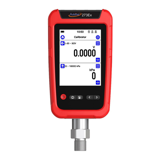
Page 28: Calibrator
3. Calibrator The ADT273Ex calibrator can be used to calibrate and measure pressure, as shown in Figure 5. Channel 1 at the top of the screen is mainly used for electrical signal measurement. It has several types of signals to be selected. Channel 2 at the bottom of the screen is mainly used for pressure measure functions, which has up to 4 pressure channels. -
Page 29: Electrical Measurement
3.1 Electrical Measurement 3.1.1 Voltage measurement Please connect electrical leads correctly as shown in Figure 6, based on your application. Then switch the measurement signal of channel 1 to voltage measurement using the icon in the top left. In order to ensure measurement accuracy and adapt to more usage scenarios, two different ranges can be selected Figure 7 Current Measurement Figure 6 Voltage / Frequency / Pulse / Switch Measurement for voltage measurement in this device: (-30~30)V... -
Page 30: Frequency Measurement
3.1.3 Frequency measurement The wiring of the frequency measurement function is the same as the voltage measurement. Please connect correctly as shown in Figure 6. Then switch the measurement signal of channel 1 to frequency measurement (0.01~50k)Hz 3.1.4 Pulse measurement The wiring method of the pulse measurement function is the same as the voltage measurement. -
Page 31: Filter
3.1.6 Filter The calibrator provides two filtering methods: first-order linear filtering and moving average filtering to process data to meet the needs of different usage scenarios. Click the menu button of the measurement channel, select the filter menu item in the pop-up menu, and the filter setting interface will be displayed (see Figure 8). Figure 8 Filter settings... -
Page 32: Scaling
Table 5 Filter configurations Valid Value Description Subject Enable/disable Enable/disable Enable or disable the filter function Method first-order linear filter or moving average filter Filtering method Only available when the first-order Filter coefficient 0 ~ 1 linear filter is selected Only available when the moving Number of samples 1~50... -
Page 33: Hart Communications
Figure 9 Scaling configurations 3.2 HART Communications Click the HART application icon on the main page, or switch the measurement channel to the HART measurement in the main interface of the calibrator to enter the HART communication function. HART communication provides the search, process variables selection, setting, diagnosis and testing of the transmitter functions. -
Page 34: Search And Connection
Figure 10 Internal power + internal resistance Figure 11 External power + external resistance 3.2.1 Search and connection Click the manual search option in the calibrator HART measurement channel to enter the power supply mode selection page (if you select the HART application from the main page, the first entry is the power supply mode selection page), in this page you can select the internal power supply with internal resistor or external power supply with external resistor. -
Page 35: Setting
3.2.2 Setting The setting items of the transmitter are divided into three categories, device information, sensor information and device output. 1.Device Information Table 7 Transmitter device information Subject Valid Value Description Manufacturer Read only Transmitter manufacturer Device type Read only Transmitter device type Device ID Read only... -
Page 36: Diagnosis And Service
transmitter Device version of the Device Version Read only transmitter 2. Sensor information Read the information on transmitter's unit, upper-lower limits, and the minimum span. 3. Device output Table 8 Transmitter device output Subject Valid Value Description Process Variable/Range °C, °F, °R, K Measurement unit of the transmitter Units Lower Limit of PV Range... - Page 37 as a calibration target are available only when the polling address of the transmitter is 0. These functions cannot be completed in multi-point access mode (when the searching/polling address is 1~15). That is because the current output is fixed at around 4mA under this mode. If the user needs to adjust, they must set the polling address to 0 in the HART settings.
- Page 38 Figure 13 PVAO zero 2. Main Variable Zero Set the zero point of the pressure transmitter to correct the zero offset of the transmitter. Under the zeroing mode, please select the pressure module connected to the device as the standard module. Then the upper channel in the interface displays the pressure value output by the transmitter, and the lower channel displays the pressure value measured by the selected standard module of the machine.
- Page 39 3. D/A Adjustment By adjusting the current output of the HART transmitter, the zero point (4mA) and full scale (20mA) output values of the transmitter PVAO are consistent with the actual output loop current value. Take D/A zero calibration as an example. After entering this calibration mode, the upper channel of the interface displays the current signal value actually measured by the calibrator (ADT226/227), the lower channel displays the current value of PVAO zero point, which is fixed at 4 mA.
- Page 40 Figure 15 Range migration 4. Range migration The transmitter range migration function allows users to flexibly map the original range of the transmitter. 5. Sensor trim The calibrator provides sensor trim function for HART transmitters, which is generally divided into low-end adjustment and high-end adjustment.
- Page 41 Figure 16 Sensor trim Figure Figure 17 Process variable selection...
-
Page 42: Process Variable Setting
3.2.4 Process variable setting The HART transmitter has a variety of process variables to choose from, and the calibrator provides the function of viewing and selecting the process variables of the transmitter. Table 9 HART process variable Subject Description The unit of the master variable depends on the setting of the transmitter. Please refer to transmitter’s Process Variable output setting for details Output current... -
Page 43: Filter
Table 10 Pressure measurement settings Subject Valid Value Description Resolution 4/5/6 Resolution of current measurement channel Pressure type GP/ AP Current measurement channel pressure type Data acquisition frequency of the current measurement Measurement frequency 1~10Hz channel Stability enable Enable/disable Whether to turn on the stability judgment function A value for judging whether the pressure is stable. -
Page 44: System Settings
4. System settings On the main page of the device, click the system setting button in the middle of the bottom to enter the system setting interface. System maintenance, system calibration, and various basic system settings are provided in the system settings. -
Page 45: Services
4.4 Services 4.4.1 Maintenance This function is only open for manufacturer. 4.4.2 Restore to factory data Enter the password for this function, default password is 123456. • Restore to the factory data will not restore the system calibration data. 4.4.3 Running information Running information includes the barometric reading, current battery voltage and electric module information. -
Page 46: Language
4.5.2 Language The device provides a multi-language user interface. Use this menu to change between the provided languages. • After the language is selected, the device needs to be restarted for the changes to take effect. 4.5.3 Date & Time The device provides customizable settings for time and date, as shown in Table 21. -
Page 47: Data Management
5. Data management On the main page of the device, click the file management button in the middle of the bottom to enter the file management interface. The file management interface is classified and managed by functional modules, and the data saved by each function is managed in the corresponding folder for convenience. -
Page 48: Dial Pressure Gauge And Digital Pressure Gauge Calibration
the icon indicates that the DUT has passed the test and meets the accuracy of the task. Click any of the tasks in the list to view and edit the task details and data. 6.1 Dial pressure gauge and digital pressure gauge calibration 1. -
Page 49: Pressure Transmitter (Voltage, Current And Hart)
4. Finish the task After the task is finished, click the save button to go to the Saving interface, fulfill the information required and save the task data of the result. Table 14 Save task data setting Subject Valid value Description Name Numbers, letters, symbols... -
Page 50: Pressure Switch
Output range Numbers Output range of DUT Transfer Linear / square root Transfer function of the DUT function Accuracy of DUT. If choose custom, the input number means the 0.06%, 0.1%, 0.16%, 0.25%, 0.4%, 0.6%, Accuracy accuracy level of the DUT. For example: input 1.5 for level of 1.5, 1%, 1.6%, 2.5%, 4%, custom the range is (0.001~100) Process... - Page 51 Table 16 Pressure switch task setting Subject Valid value Description Pressure type Gauge/ absolute/ differential Pressure type of DUT Input range Numbers Input range of DUT Set action type Opened / closed Action type of the DUT Set point Value Action set point of the DUT Accuracy of DUT.
-
Page 52: Applications
7. Applications 7.1 Units converter The calibrator provides a unit converter for pressure units and temperature units. Users can select multiple pressure units or temperature units for conversion. Click the unit converter icon on the main interface of the device to enter the unit converter. -
Page 53: Psv Test
pressure - real time pressure; e. Record the pressure at the end of the test time as the end pressure; f. The entire leak detection process ends, and the final leakage = initial pressure - end pressure; 2. The whole process will be displayed in stages in the leak curve at the bottom of the screen. 7.3 PSV test The calibrator provides function of PSV test, to test the safety pressure of the safety valves. - Page 54 Table 19 Pressure delta setting Project Effective value Description Enable or disable the differential pressure module. When the differential pressure module is enabled, the differential pressure Enable Enable / disable module channels will be displayed in the related functions channel list. Resolution 4/5/6 The resolution of differential pressure...
-
Page 55: Wiring Help
7.5 Wiring help The wiring help function in the calibrator can help users to connect the wires correctly under various working conditions of the calibrator. It can be entered by clicking the "Wiring help " menu in each channel, or by clicking the "wiring help" icon in the main interface of the device.
Need help?
Do you have a question about the 273E Series and is the answer not in the manual?
Questions and answers