Advertisement
Quick Links
Advertisement

Related Manuals for MEWOI MEWOI-HY128 Series


Summary of Contents for MEWOI MEWOI-HY128 Series
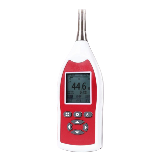
- Page 1 Sound Level Meter MEWOI-HY128 Series User Manual www.mewoi.com...
-
Page 3: Table Of Contents
CONTENT Brief Introduction ............... 1 Specifications and technical parameters......... 16 III. Main structure and working principle ........21 Use and operation ..............22 Fault analysis and elimination ..........68 Complete set of products ............71 VII. Maintenance of the instrument ..........74... -
Page 4: Brief Introduction
I. Brief Introduction 1.1 Main purpose and scope of application HY128 series sound level meter is a digital multi-function sound level meter, designed to measure the frequency weighted and time weighted sound pressure level, equivalent continuous sound level, exposure sound level, statistical sound level, etc. of various types of noise Acoustic evaluation, it has 7 working modes of integral average, parallel... - Page 5 measurement method requirements, 24h noise monitoring meets the requirements of GB 3096-2008 "Sound Environmental Quality Standard" and HJ 640-2012 "Environmental Noise Monitoring Technical Specifications for Cities According to the requirements of "Conventional Monitoring of Acoustic Environment", the coding of environmental monitoring points meets the requirements of HJ 661-2013 "Environmental Noise Monitoring Point Coding Rules".
- Page 6 Warning!!! 1. Before using the explosion-proof product, read the product manual in detail. 2. Explosion-proof products cannot be arbitrarily connected with other equipment that has not been inspected. Power banks can only be used in non-explosion-proof environments. 3. Check carefully before use, and stop using it immediately if any abnormality is found during use.
- Page 7 Configuration 2 HY128 Class √ √ √ √ √ √ √ Configuration 3 Class √ √ HY128A HY128 Class √ √ √ (Basic) HY128B Class √ √ √ √ √ √ Configuration 1 Class √ √ HY128C Table 1 Configuration of HY128 series instruments 1.3 Working environment conditions The working environment conditions of HY128 series sound level meters are as follows:...
- Page 8 1.4 Measurement function 1.4.1 Introduction HY128 series sound level meters all have the functions of ordinary sound level meters. See Table 1 for the specific models and configurations of the functions. HY128 series sound level meters have integration time settings (time is 1s~99h59min59s, when the time is set to 0, the default is manual, as the time is set to 99h59min59s), automatic repeat measurement (time number is 1~99, When set to 1 time, it is actually a onetime measurement)
- Page 9 • Measure A frequency weighted F time weighted minimum sound level. 1.4.3 Integral Average The measurement mode of HY128 series sound level meter has integral average. In this mode, the frequency weighting has A, C and Z weighting, and the time weighting has F, S and I weighting. It provides the operator to choose the appropriate frequency and time weighting.
- Page 10 weighting, and time weighting is only F weighting. The main measurement: • A frequency weighted time average sound level (equivalent continuous sound level); • 1s short-term A frequency weighted time average sound level (short-term equivalent continuous sound level); • A frequency weighted F time weighted sound level; •...
- Page 11 time; • The minimum value of the weighted sound level at each time (Lmin); • Average sound level at each time (LeqT, equivalent continuous sound level); • Weighted peak sound level of each frequency (Lpeak); • Sound exposure level (LE); •...
- Page 12 ——A frequency weighted F time weighted minimum sound level; ——A frequency weighted sound exposure level; ——Statistical sound level LN (the percentage N is 5, 10, 50, 90 and 95); -Standard deviation SD. 1.4.7 Indoor noise measurement modes HY128 (configuration (configuration 2), (configuration 3) sound level meters and HY128B (configuration 1) sound level meters include indoor noise measurement.
- Page 13 1.4.8 1/1 octave measurement modes HY128 (configuration (configuration 3) sound level meters and HY128B (configuration 1) sound level meters have 1/1 octave measurement, including 11 1/1 octave filter center frequencies: 16 Hz, 31.5 Hz, 63 Hz, 125 Hz, 250 Hz, 500 Hz, 1 kHz, 2 kHz, 4 kHz, 8 kHz and 16 kHz. In this mode, the frequency weighting has A, C and Z weighting, and the time weighting has F and S weighting.
- Page 14 kHz, 2.5 kHz, 3.15 kHz, 4 kHz, 5 kHz, 6.3 kHz, 8 kHz, 10 kHz, 12.5 kHz, 16kHz and 20kHz. In this mode, the frequency weighting has A, C and Z weighting, and the time weighting has F and S weighting.
- Page 15 Page Right External power supply sign Measurement result interface under-range mark Threshold start flag Timing start flag Code Environmental monitoring point (dB) Sound level measurement unit A frequency weighted acoustic exposure C-frequency weighted acoustic exposure Z-frequency weighted acoustic exposure F time weighting A standard time weighting used for sound level meters FreqWt Frequency weighting...
- Page 16 A frequency weighted and F time weighted sound level A frequency weighted and F time weighted maximum LAFmax sound level A frequency weighted and F time weighted minimum LAFmin sound level A frequency weighting and pulse time weighting sound level A maximum sound level weighted by frequency and pulse LAImax time...
- Page 17 C frequency weighting and F time weighting maximum LCFmax sound level C frequency weighting and pulse time weighting sound level C frequency weighting and pulse time weighting LCImax maximum sound level LCpeak C frequency weighted peak sound pressure level C frequency weighting and S time weighting sound level C frequency weighting and S time weighting maximum LCSmax sound level...
- Page 18 of the average value of Z-weighted sound pressure level over time during the measurement period, in dBs. Z frequency weighting and F time weighting sound level Maximum sound level with Z frequency weighting and F LZFmax time weighting Z frequency weighting and F time weighting minimum LZFmin sound level Z frequency weighting and pulse time weighting sound...
-
Page 19: Specifications And Technical Parameters
II. Specifications and technical parameters a) Performance level Level 1 or Level 2 specified in GB/T 3785.1-2010/IEC 61672-1:2013. Category X specified in GB/T 3785.1 - 2010/IEC b) Electromagnetic field radiation and immunity 61672-1:2013. classification c) Frequency weighting A weighting;C weighting; Z weighting;Low (low frequency).Note:When A weighting is selected, and Low ( √... - Page 20 low battery voltage. j) Measuring range at 1 30 dB (A)~130 dB (A); 40 dB (C)~130 dB (C); kHz frequency 45 dB (Z)~130 dB (Z Note: (1) The measurement range on other frequencies is the sum of the upper and lower limits of the measurement range of the instrument and the nominal value of the frequency weighting specified in the national standard GB/T 3785.1-2010, but the upper limit...
- Page 21 Note: Explosion-proof products can only use LR6 alkaline batteries. o) Power Bank Because the quality of the battery and the battery discharge performance (new and old) are not qualitative, when the instrument measures for a long time (including 24h measurement), it is recommended to use the company's dedicated power bank (Sunny Care) for power supply.
- Page 22 and the Class 2 sound level meter does not exceed ± 1.0 Temperature Temperature: -20℃ and +60℃; humidity limit values that Relative humidity: 95%. cause permanent damage to the sound level meter z) Adjustment data of Through the sound pressure response generated by the sound pressure response sound calibrator or the simulated sound pressure and free field response...
- Page 23 上限 值 典型响 应 下 限值 - 1 0 - 1 2 3 1 . 5 1 2 5 2 5 0 5 0 0 1 6 k Figure 1 Typical frequency response of microphone Figure 2 The directivity characteristics of the sound level meter at different frequencies...
-
Page 24: Main Structure And Working Principle
Frequency/ Free field Frequency/ kHz Free field increment / dB increment / dB 1.25 12.5 3.15 — — Table 3 Free field response adjustment data III. Main structure and working principle The H128 series sound level meter is mainly composed of a microphone, a preamplifier, a conditioning circuit, a single-chip circuit, a power supply circuit, a display circuit, and a button circuit. -
Page 25: Use And Operation
conditioning circuit conditions the signal output by the preamplifier and sends it to the 24bit ADC. The single-chip microcomputer controls the ADC and receives the digital signal that it outputs, performs frequency weighting, time weighting, detection and logarithmic conversion on the signal, and sends it to the display circuit for display. - Page 26 4.1 The role of each control element Microphone Backlight Display Tripod mount Control Keypad Battery Cover Figure Outline drawing The control device on the HY128 series sound level meter is shown in Figure 3, and its functions are as follows: 1) Microphone: HY 205 or HY207 12.7 mm pre-polarized condenser microphone.
- Page 27 4) Battery cover: Open or close the battery cover in the direction of the arrow head to facilitate battery replacement. 5) Tripod mounting hole: 1/4 inch screw hole, used to install the sound level meter on the tripod. 4.2 The output interface of the instrument On the side of the lower end of the sound level meter, open the port cover to see the output interface of the instrument, as shown in Figure 4.
- Page 28 accordance with the polarity marked in the battery box, and remember not to install it backwards! In use, if the display shows that the battery voltage sign is empty and flashes at the bottom left, it indicates that the battery voltage has fallen below the specified working voltage, and the battery should be replaced in time.
- Page 29 4.4 Button The schematic diagram of the buttons is shown in Figure 5. Function key 1 Power key Function key 2 Function key 2 Function key 2 Function key 2 Function key 2 Figure 5 Schematic diagram of buttons Button function description: Function key 1: This key has different functions in different interfaces.
- Page 30 "value increment and selection" in the setting parameter interface. Power key: Long press to turn on or off the instrument (shutdown must be in the main interface), and it is also used as a function key. This key has different functions in different interfaces and realizes the use of the "reset, return, exit, stop, and no"...
- Page 31 the value, press the "calibration" key (function key 1) to start calibration, and the remaining time of calibration will be displayed in the center of the display. f) After calibration, “LAF” displays the calibrated sound level, and at the same time “Success” will be displayed at the bottom of the display.
- Page 32 4——Function key area, the three function keys correspond to the three keys on the top of the panel, the leftmost "function key 1" corresponds to confirm, the middle "function key 2" corresponds to calibration, and the "power key" corresponds to reset (short press, long press For shutdown).
- Page 33 calibrator used, otherwise it should be corrected according to the requirements of the sound calibrator's instruction manual. 4. To calibrate the sound level meter in a situation with high background noise, the 114 dB gear of HY604/HY603 should be used. Although the HY128 series sound level meters have high stability and only require periodic adjustments, it is still recommended to perform a calibration check before and after each measurement.
- Page 34 cursor to "LCD" item, press "Enter" key to enter directly, brightness can be selected from 0 to 9 (10 kinds), it is recommended to select brightness "5", "Up/Down Arrow" key to modify the brightness value, press "Enter" key to save the modification and return, or press the "Return"...
- Page 35 move the cursor, "Up/Down Arrow" key to modify the value, after the modification, press "Confirm" "Button to save the modification and return. If you select "Automatic printing (√)", please connect the printer before measurement. After the measurement is completed, no operation is required and it will automatically print. Notice: 1) The printer's baud rate is generally set to 9600.
- Page 36 Figure 8 Settings in the main interface 4.7 Mode In the main interface, move the cursor to the "Mode" item, and press the "OK" key (function key 1) to enter the measurement mode interface. There are 7 measurement modes, "integral average", "statistical analysis", "24h measurement", "parallel measurement", "indoor noise", "octave"...
- Page 37 means "24h measurement", "PAR" means "integral parallel", "IND" means "indoor noise", "OCT" means "octave", "3RD" means "1/3 octave". 4.9 Measurement 4.9.1 Ordinary sound level meter The main interface of the HY128 series sound level meter has the function of an ordinary sound level meter, as shown in Figure 6, which can measure LAF, LAFmax, and LAFmin.
- Page 38 Figure 9 Settings in the integration average interface Notice: 1. If the "Integration Time" item is set to 00:00, then the marked integration time is set to "Manual". 2. After the start mode of the "Start Mode" item is set, there is a corresponding mark at the bottom left of the integral average interface, which is set to "Threshold", the mark is...
- Page 39 measurement. 4.9.2.2 Integral average The steps of integral average measurement are as follows: a) Turn on and calibrate according to method 4.5. b) Select the "Mode" item, press the "OK" key (function key 1) to enter the measurement mode, select "Integral average", press the "OK"...
- Page 40 the upper limit of the sound level measurement range. If the middle right end of the display shows the under-limit mark “ ”, it indicates that the measured sound level is below the lower limit of the sound level meter's range. f) When the integration time is up to automatically stop the measurement or manually stop the measurement, the sound level meter enters the measurement result display interface, as shown...
- Page 41 can press and hold the power button to shut down. Figure 10 Integral average interface 4.9.3 Statistical analysis 4.9.3.1 Settings in statistical analysis mode In the statistical analysis interface, press the "Settings" key (function key 2) to enter the statistical analysis settings, as shown in Figure 11.
- Page 42 move the cursor, and the "up/down arrow" key to modify the value or method, After setting, press the "OK" key (function key 1) to save and return. Figure 11 Settings in the statistical analysis interface Notice: 1. If the "Integration Time" item is set to 00:00, then the marked integration time is set to "Manual".
- Page 43 integration average interface, press the "start " key to start. 4.9.3.2 Statistical analysis The steps of statistical analysis and measurement are as follows: a) Turn on and calibrate according to method 4.5. b) Select the "Mode" item, press the "OK" key (function key 1) to enter the measurement mode, select "Statistical Analysis", and press the "OK"...
- Page 44 printed. g) Press the "return" key (power key) to return to the statistical analysis interface for the next measurement. h) After the measurement is completed, return to the main interface. It is recommended to check the sensitivity of the sound level meter with a sound calibrator to ensure the accuracy and reliability of the measurement data.
- Page 45 Figure 12 Statistical analysis interface 4.9.4 24h measurement 4.9.4.1 Setting in 24h measurement mode In the 24h measurement interface, press the "Settings" key (function key 2) to enter the statistical analysis settings, as shown in Figure 13. There are mainly "measuring point code, integration time, starts mode, synchronization and mode"...
- Page 46 press the "OK" key (function key 1) to save and return. Figure 13 Settings in the 24h measurement interface Notice: 1. "Integral time" item is not allowed to be set to 00:00:00. 2. After the start mode of the "Start Mode" item is set, there is a corresponding mark at the bottom left of the integral average interface, which is set to "Threshold", the mark...
- Page 47 "Asynchronous" means that the "minutes and seconds" of each subsequent measurement time are the same as the "minutes and seconds" of the first measurement time. 4.9.4.2 24h measurement The steps of 24h measurement are as follows: a) Turn on and calibrate according to method 4.5. b) Select the "Mode"...
- Page 48 measurement result interface, as shown in Figure 14. At this time, the first group of measurement results can be viewed. g) When the second group of measurement time is up, the instrument automatically starts the second group of measurement. h) After 24 groups of measurements are completed, in the measurement result interface, you can choose to view and print.
- Page 49 Figure 14 24h measurement interface Notice: 1. One measurement in "24h measurement" contains 24 groups (hours) of measurement data. 2. If the sound level meter will not be used for a long time, be sure to take out the battery to prevent damage to the instrument due to battery leakage! 3.
- Page 50 4. For 24h measurement, considering the capacity of the battery, it is recommended to use the special power bank provided by the company for power supply. 4.9.4.3 A few remarks a) HY128 series sound level meter samples in a period of 1.33ms, and the display is refreshed in a period of 1s, that is, only one of the 750 sampled values is sent to the display, and the overload sign indicates the current state, so the overload sign is displayed,...
- Page 51 enter, the "left/right arrow" key to move the cursor, and the "up/down arrow" key to modify the value or method, After setting, press the "OK" key (function key 1) to save and return. Figure 15 Settings in the integration parallel interface 4.9.5.2 Integral Parallel The steps of integrating parallel measurement are as follows: a) Turn on and calibrate according to method 4.5.
- Page 52 interface, as shown in Figure 16. c) Set the parameters of "Measuring point code, integration time, repeated measurement and start mode" according to 4.9.2.1 method. d) Press the "start" key to start the measurement. During the measurement, press the "up/down arrow" key to view the time-weighted instantaneous sound...
- Page 53 is 2 times or more, the sound level meter will automatically perform the next measurement according to the settings after the sound level meter has completed one measurement. 2. If the sound level meter will not be used for a long time, be sure to take out the battery to prevent damage to the instrument due to battery leakage! 3.
- Page 54 time, room type, repeat measurement and start mode" parameter settings. The operation is as follows: use the "up/down arrow" key to move to the modification item, press the "modify" key (function key 1) to enter, the "left/right arrow" key to move the cursor, and the "up/down arrow"...
- Page 55 enter the measurement mode, select "Indoor noise", and press the "OK" key to enter the indoor noise measurement interface, as shown in Figure 18. c) Set the parameters of "Measuring point code, integration time, room type, repeat measurement and start mode" according to the method 4.9.2.1.
- Page 56 Figure 18 Indoor noise measurement 4.9.7 Octave 4.9.7.1 Setting in octave mode In the octave interface, press the "set" key (function key 2) to enter the octave setting, as shown in Figure 19, there are mainly "measuring point code, integration time, room type, repeat measurement and start mode"...
- Page 57 Figure 19 Setting in octave 4.9.7.2 Octave The octave steps are as follows: a) Turn on and calibrate according to method 4.5. b) Select the "Mode" item, press the "OK" key (function key 1) to enter the measurement mode, select "Octave", and press the "OK" key to enter the octave measurement interface, as shown in Figure c) Set the parameters of "Measuring point code, integration time, weighting, repeated measurement and start mode"...
- Page 58 measurement values under A, C, and Z weighting, see Figure 20. e) When the integration time is up to automatically stop the measurement or manually stop the measurement, the sound level meter enters the measurement result display interface, as shown in Figure 20.
- Page 59 Figure 20 Octave measurement 4.9.8 1/3 octave band 4.9.8.1 Setting in 1/3 octave mode In the 1/3 octave interface, press the "Settings" key (function key 2) to enter the 1/3 octave setting, as shown in Figure 19, mainly...
- Page 60 including "measuring point code, integration time, room type, repeat measurement and start Mode" parameter setting. The operation is as follows: use the "up/down arrow" key to move to the modification item, press the "modify" key (function key 1) to enter, the "left/right arrow"...
- Page 61 3.15 kHz, 4 kHz, 5 kHz, 6.3 kHz, 8 kHz, 10 kHz, 12.5 kHz, 16kHz and 20kHz) and the equivalent continuous sound level, maximum, minimum and Tm measurement values under A, C, and Z weighting, see Figure 21. e) When the integration time is up to automatically stop the measurement or manually stop the measurement, the sound level meter enters the measurement result display interface, as shown in Figure 21.
- Page 62 Figure 21 1/3 octave frequency measurement...
- Page 63 4.9.9 Print measurement data 4.9.9.1 Mini printer and its usage HY128 can optionally be equipped with a mini printer with a serial interface to print the measurement results. It is recommended to use the RD-V32-SN portable micro thermal printer or RG-MDP58C needle type printer supplied by Hunan Shengyi Measurement and Control Technology Co., Ltd.
- Page 64 flashes blue, and the printer beeps after turning on. In the power-on state, the indicator light flashes about once every 6 s. In the power-on state, press the power button (P) once, the indicator light flashes red, and then it shuts down. Figure 22 RD-V32-SN portable mini thermal printer Instruction: 1——Serial interface (end face);...
- Page 65 a) Loading paper RD-V32-SN printer adopts easy-to-load paper structure and thermal printing paper with an effective width of 50 mm. When loading paper, pinch both sides of the paper compartment cover with your fingers to open the paper compartment cover and open the paper compartment cover.
- Page 66 state, and the printer will print the self-check containing the model, specification and manufacturer information strip. After printing, the printer automatically exits the self-check state. e) Online status When the blue indicator light on the right side of the printer is on, it indicates that the printer is online.
- Page 67 charging ends. Notice: 1. The instructions of different batches of printers may be different, please refer to the printer's instruction manual. 2. If the printer is not used for a long time or does not work normally, please cut off the printer's power supply. 3.
- Page 68 After printing, press the power button "P" on the printer again to ensure that the printer's power is turned off. Note: Please use the RD-V32 miniature printer recommended by MEWOI Company, and make sure that the rechargeable battery inside the printer is sufficiently charged.
- Page 69 、...
- Page 70 Figure 23 Print measurement report 4.9.10 Analog output and wiring HY128 series sound level meters are equipped with AC voltage and DC voltage output signals. In order to reduce the volume, the AC and DC outputs share a 3.5mm dual-channel jack. External instruments (such as digital multimeters, recorders, etc.) can be connected to the output of the sound level meter through the 3.5mm plug that comes with the machine.
-
Page 71: Fault Analysis And Elimination
voltage does not exceed 2V. Figure 24 Connection of analog output plug V. Fault analysis and elimination This chapter includes methods to help solve some simple operational problems that you may encounter, as well as some common fault phenomena, possible causes and troubleshooting methods. - Page 72 battery installed Remove the battery and check the correctly polarity of the battery Try again after turning on the sound Sound calibrator is not turned on calibrator Check whether the installation of the The sound calibrator is not installed sound calibrator is consistent with the correctly accompanying instructions microphone...
- Page 73 abnormal The internal circuit of the sound Ask the company or your local agent for level meter is damaged help Measurement Memory full Check available memory not stored Measurement is not reset Restart measurement The measurement Automatic synchronization Turn on automatic synchronization synchronized turned off with the clock...
-
Page 74: Complete Set Of Products
VI. Complete set of products 6.1 Main accessories and their applications In order to further improve the performance of the sound level meter and facilitate inspection and adjustment, HY128 has many accessories, the main functions of which are as follows: (1) Dust cover Set on the microphone of the sound level meter, it can prevent dust from intruding into the microphone, and at the same time, it has... - Page 75 6.2 Accessories to be ordered separately and their uses (1) Acoustic calibrator The sound calibrator is used to calibrate the entire sound level meter. The HY603 type sound calibrator is a class 2 sound calibrator, which can generate two standard equivalent sound pressures with a frequency of 1000 Hz and a sound pressure level of 94 dB and 114 dB.
- Page 76 in the carrying case for a long time). 6.3 List of product sets See Table 5 for the complete set of products of HY128 series sound level meters. Note: The accessories of each sound level meter are subject to the delivery list.
-
Page 77: Maintenance Of The Instrument
Accessories Sound HY604 Calibrator Tripod Big/Mid/Small Carrying Case HY7711 Power Adaptor USB Charger Printer Documents User Manual Product Maintenance of the instrument Certificate General precautions In order to prevent damage to the sound level meter due to improper use and operation, the following matters are specially drawn: (1) Take out the battery immediately after use to avoid battery leakage and damage to the instrument. - Page 78 trichloroethylene or acetone to gently wipe it clean. (5) Do not touch the input contacts with your hands to prevent damage to the sound level meter due to static electricity on the human body. (6) Liquid crystals are organic compounds. If they are exposed to strong ultraviolet radiation for a long time, a photochemical reaction will occur.
- Page 80 Your Testing Specialist...
Need help?
Do you have a question about the MEWOI-HY128 Series and is the answer not in the manual?
Questions and answers