Table of Contents
Advertisement
Quick Links
Advertisement
Table of Contents

Related Manuals for MEWOI MEWOI-JY218


Summary of Contents for MEWOI MEWOI-JY218
- Page 1 Sound Level Meter MEWOI-JY218(Class 1) User Manual www.mewoi.com...
-
Page 3: Table Of Contents
CONTENT Brief Introduction ............... 1 First time use ................1 III. Technical Specification .............. 1 Structure ..................3 Display interface ................ 4 Keypad interface ............... 5 VII. Instrument operation ..............5 VIII. Calibrating the meter ..............8 Reference Information for Periodic Testing ....... 8 Serial connection .............. -
Page 4: Brief Introduction
Brief Introduction Welcome to your new sound level meter. You’ve taken a great step towards protecting people’s hearing and this entry level meter will make it quick and easy for you to take simple noise measurements, providing you with the basic data you need. It is designed to IEC 61672 to Class 1. - Page 5 Noise floor < 25dB (A) and 35dB (C) Display flags Alarm Limit, Overload, Under-range Auto calibration ±4.5dB range Reference point 94dB (1kHz), 92.9dB (8kHz) Settling time Display Backlit 128×64 LCD Resolution 0.1dB Electrical inputs 5V power in via mini USB 2 x AA/LR6 1.5V batteries Power or 5V DC via Mini USB input...
-
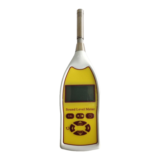
Page 6: Structure
IV. Structure Microphone Backlight Display Tripod mount Control Keypad Battery Cover Connectors RS232 for Printer AC/DC Output USB Power Input 1. Microphone 2. Backlight Display 3. Control Keypad 4. Connectors 5, Connectors 6, Tripod mount 7, Battery Cover 8, RS232 9, AC/DC Output 10, USB... -
Page 7: Display Interface
V. Display interface 1, Main Display Under-range Measurement Overload indicator Indicator indicator Measurement Type Measurement Data Battery Level 2, Calibration display (press the CAL button) Calibrator level Correction to Be applied Measurement Data 3, Measurement display Under-range/ Overload Overall Indicator Measurement Value Measurement Duration... -
Page 8: Keypad Interface
VI. Keypad interface Measurement start/stop Perform calibration Measurement start/stop Soft key: CAL/Print Time weighting toggle Select/View Reset max, min, LCpeak Frequency weighting toggle VII. Instrument operation Fit new batteries by sliding the battery cover open and inserting two AA batteries in the correct orientation. Switch on and allow the instrument to settle for 60 seconds before calibrating. - Page 9 The measurement type is displayed in the main window: LAF - A frequency weighting and fast time weighting LCF - C frequency weighting and fast time weighting LZF - Z frequency weighting and fast time weighting LAS - A frequency weighting and slow time weighting LCS - C frequency weighting and slow time weighting LZS - Z frequency weighting and slow time weighting LAI - A frequency weighting and impulse time weighting...
- Page 10 is running, the latest values will be displayed on the screen, with the measurement duration shown at the bottom. Alternative measurement parameters can be viewed by pressing the left/right arrow buttons. Overload and under-range are denoted by the ^ and v indicators in the top right corner of the screen.
-
Page 11: Calibrating The Meter
VIII. Calibrating the meter Before making a measurement, it is important that you calibrate your instrument with an acoustic calibrator. To start the process of calibration, ensure the microphone is fitted correctly and place the acoustic calibrator over the microphone. Press to enter the calibration menu. - Page 12 Linear range 4kHz 30-130dB Linear range 1kHz 30-130dB LCPeak maximum (500Hz, 1kHz, 8kHz) 133dB Self-generated noise floor A weight = 25dB C weight = 35dB Self-generated noise floor with mic fitted A weight = 25dB C weight = 35dB Dummy microphone capacitance 18pF Recommended dummy microphone HY7314...
- Page 13 Case reflection and windshield attenuation data. Frequency/kHz Case Correction Windshield Uncertainty Correction 0.27 0.27 0.13 0.05 0.27 0.18 0.08 0.27 1000 0.09 0.27 2000 -0.16 0.26 0.27 4000 0.01 0.53 0.32 8000 -0.10 0.26 0.30 16000 -0.17 -0.58 0.29 Add the above data to your measurement to correct. Directionality plots and case reflection plots -10-...
-
Page 14: Serial Connection
X. Serial connection DB9, RS232 communication rate at 9600 Baud. 1 bit start, 8 bits data, 1 bit stop, no parity. Command Code Description (ASCII) Instant level Send instant level after receiving command 'L'. Maximum level Send maximum level after receiving command 'M'. Minimum level Send minimum level after receiving command 'N'. - Page 15 weighting Z after receiving the command 'F', and then send 'F' as the response. Toggle time weighting Toggle the time weighting between F and S after receiving the command 'T', and then send 'T' as the response. Please note that commands 'R', 'F', and 'T' will not work out if the measurement is on-going, because the parameters cannot be changed during the measurement.
- Page 16 esting pecialist...
Need help?
Do you have a question about the MEWOI-JY218 and is the answer not in the manual?
Questions and answers