Table of Contents
Advertisement
Quick Links
Advertisement
Table of Contents

Related Manuals for MEWOI MEWOI1200


Summary of Contents for MEWOI MEWOI1200
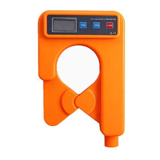
- Page 1 H/L Voltage Clamp Meter MEWOI1200,MEWOI1200C...
-
Page 3: Table Of Contents
CONTENT Warning ....................1 Ⅰ. Brief Introduction ................3 II. Electrical Symbols ................4 III.Series Model .................. 5 IV.Technical Specification ..............5 V. Structure ................... 7 VI.LCD Display .................. 8 VII.Operation ..................10 A. Tester Operation ................10 1. Power On/Off ................10 2. - Page 4 VIII. Replacing Batteries ..............16 IX. Accessories ................... 17...
-
Page 5: Warning
Warning Thanks for your purchase of MEWOI1200 H/L Voltage Clamp Current Meter of our company. In order to make better use of this product, please make sure to: ——Read this manual in detail and the operator must totally understand this manual and be in proficient in operation of this meter before making test on spot. - Page 6 To avoid the impact of transducer clamp, it needs to maintain this meter regularly. Do not use corrosive or coarse materials to clean, but use soft cloth (such as glasses cloth), dipping clean anti-rust desiccant lubricant (such as WD-40), and making a gentle wiping.
-
Page 7: Ⅰ. Brief Introduction
Ⅰ. Brief Introduction MEWOI1200 Series H/L Voltage Clamp Current Meter has broken through the traditional structure, which is specially well-designed for measuring high voltage current, adopt latest CT technology and integrated mask digital technology, composed of special clamp current meter and high voltage insulation rods. -
Page 8: Electrical Symbols
inspection station and electrician maintenance departments for electrical current detection and field electrical operations. It can also replace the H/L voltage transforming ratio tester, that is, to detect the high and low current for primary circuit and secondary circuit separately, and then calculate to conclude the change of high and low pressure. -
Page 9: Series Model
III.Series Model Range of Model Accuracy Description measurement Specification Base MEWOI1200 0.00mA-1000 Φ68mm 0.01mA Wireless MEWOI1200C IV.Technical Specification High voltage AC current measurement, low voltage AC current, leakage current Function measurement, on-line AC current supervision. Power Supply DC6V Alkaline Dry Battery (1.5V AAA X 4) - Page 10 Receiver LCD:47mm×28.5mm Tester: 218mm×135mm×60mm Meter Dimension Receiver: 170mm×75mm×30mm 99 Groups, during storage, the symbol “MEM” gives indication, “FULL” mark will flash to Data Storage indicate the memory has been full. Automatically maintain the height of the tes t value,usually in the test mode press PE Peak “PE”...
-
Page 11: Structure
receiver:About 220g (Including battery) Total quality of meter: about 2.3kg(including insulation rod and battery) Work Temperature and -10℃~40℃;≤80%Rh Humidity Storage -10℃~ 60℃; ≤70%Rh Temperature and Humidity Avoid same frequency interfere(315MHz & Interference 433MHz) Insulated Rod φ32mm, 1m/ Section(5 Sections) Dimension Tester/receiver:AC 2kV/rms(Between core and shell) Insulation... -
Page 12: Lcd Display
test test(wireless) receiver VI.LCD Display 1.Explanation for Special Symbols ⑴. Low battery symbol, when the voltage of battery is lower than 4.8V, this symbol display, please replace battery in time. ⑵.“OL A” This symbol indicates that the current on test has exceeded the maximum measurement limit of the meter. - Page 13 process. ⑷. “Full” symbol, when the storage memory has been filled with 99 groups of data, it will display “FULL” symbol by flash, which means it cannot continue to store data. ⑸.“MR” data access symbol, which is displayed during looking up data, meanwhile, it will display the serial number of data in storage.
-
Page 14: Operation
⑷.——Look up data of group 3 in storage ——The current on test is: 160.5A ⑸.—— “FULL” flash display: Storage is full of 99 groups ——It can’t store more unless delete storage ⑹.——“dEL” Indication of data delete ⑺.—— “End” Indication of exit *⑻.——“no- -”Dynamic display: none received signal VII.Operation... -
Page 15: General Test
continuous flash, press POWER button, then the meter will continue to work. Under HOLD mode, press POWER button for power off. Under general test mode, press POWER button to power off. Under PEAK testing mode,press POWE button to power off. Under data reference mode, firstly press POWER button for more than 3 seconds to exit from data reference mode, returning to normal test mode, then press POWER button to power off. - Page 16 Before test, firstly to connect insulation rod, which must be connected in right position, and then to connect tester, avoiding the impact of meter to ground surface. Make sure to use specially equipped insulation rod to connect with the meter. After test, it should incline the insulation rod accordingly on drawing in.
-
Page 17: Peak Test
Under HOLD mode, press HOLD button to cancel HOLD function, and return to normal testing mode. Under data reference mode, press POWER button for more than 3 seconds to exit from data reference mode, returning to normal testing mode. Under PEAK testing mode, press POWER button to exit from PEAK testing mode, returning to normal testing mode. -
Page 18: Data Maintenance
be read directly Under the normal testing mode, press PEAK button, LCD display “PE”, enter PEAK testing mode. That means the meter will display and automatically keep the maximum value in the test. Under any other mode, it must be returned to normal testing mode, and then make PEAK testing according to the above operation. -
Page 19: B .Operation Of Receiver
transferred to receiver by wireless transmission and the receiver will display test result real time, being clear at a glance. Only under testing mode, the meter will transmit, If the receiver has not received emission signals, it will display “no - -” symbol dynamically. -
Page 20: Data Memory
again to relieve data lock, return to data reception mode, “HOLD” symbol display. 4. Data Memory Under Date Reception mode, press HOLD button to maintain data, meanwhile, the receiver will automatically form serial numbers, and memory the current preserved data. During the storage, “MEM”... - Page 21 “ ” symbol, indicating the batteries have no sufficient power content. Please replace batteries. 2. Power off, to make sure the meter is under the state of power off. To loosen two screws of the battery cover board, open the cover board to replace brand-new qualified batteries on.
- Page 23 esting pecialist...
Need help?
Do you have a question about the MEWOI1200 and is the answer not in the manual?
Questions and answers