Table of Contents
Advertisement
Quick Links
Advertisement
Table of Contents

Related Manuals for MEWOI MEWOI1000


Summary of Contents for MEWOI MEWOI1000
- Page 1 High Voltage Clamp Leaker MEWOI1000, MEWOI1000C User Manual www.mewoi.com...
-
Page 3: Table Of Contents
CONTENT Warning ....................1 I . Brief Introduction ................3 II. Electrical Symbols ................4 III.Series Model .................. 4 IV.Technical Specification ..............5 V. Structure ................... 7 VI.LCD Display .................. 8 VII.Operation ..................10 A. Tester Operation ................10 1. Power On/Off ..................10 2. - Page 4 Data Deletion ................... 16 VIII. Replacing Batteries ..............16 IX. Accessories ................... 17...
-
Page 5: Warning
Warning Thanks for your purchase of ETCR9000 series H/L Voltage Clamp Meter of our company. In order to make better use of this product, please make sure to: ——Read this manual in detail and the operator must totally understand this manual and be in proficient in operation of this meter before making test on spot. - Page 6 To avoid the impact of transducer clamp, it needs to maintain this meter regularly. Do not use corrosive or coarse materials to clean, but use soft cloth (such as glasses cloth), dipping clean anti-rust desiccant lubricant (such as WD-40), and making a gentle wiping.
-
Page 7: Brief Introduction
I . Brief Introduction ETCR9000 Series H/L Voltage Clamp Meter has broken through the traditional structure, which is specially well-designed for measuring high voltage current, adopting the latest CT technology and integrated mask digital technology, formed by composition of a special use clamp meter with a high-voltage insulation rod, as to ETCR9000B type --- wireless transmission of test data, it is equipped with wireless receivers, which can receive measured data within 30 meters line. -
Page 8: Electrical Symbols
II. Electrical Symbols Extremely Dangerous! The operator must strictly abide by the safety rules. Otherwise, there is electric injury danger, causing personal damage or casualty accident. Dangerous! The operator must strictly abide by the safety rules. Otherwise, there is electric injury danger, causing personal damage or casualty accident. -
Page 9: Technical Specification
IV.Technical Specification High voltage AC current measurement, low voltage current, leakage current Function measurement, on-line AC current supervision. Power Supply DC6V Alkaline Dry Battery (1.5V AAA X 4) Test Method Clamp CT, Integral Method *Transmission B Model: Wireless Transmission, the maximum Method distance for direct transmission is about 30m. - Page 10 PEAK function, then press PEAK key to cancel this function Under general test mode, press HOLD button Data to preserve data, “HOLD” symbol display. then Preservation press HOLD Key to cancel this function “MR” symbol indicates, it can read the stored Data Access data by turning upwards and downwards.
-
Page 11: Structure
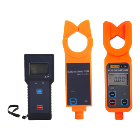
V. Structure 1. Double input toroid (including the boot area) 2. ETCR9000 Tester 3. LCD Display 4. PEAK Test Indication 5. PEAK Key 6. POWER Key 7. HOLD Key *8. ETCR9000B Receiver 9. Insulation Rod Connector *10.POWER Indication *11.ETCR9000B Testers 12.Insulation Rods*5 *13.Anntenna... -
Page 12: Lcd Display
VI.LCD Display 1.LCD Display Screen ⑴. AC symbol ⑵. Low battery symbol ⑶. Date storage symbol ⑷. Date access symbol ⑸. 2-digit storage data serial number ⑹. Unit symbol ⑺. Date locked symbol ⑻. Decimal system radix point ⑼. 4-Digit LCD digital display 2.Explanation for Special Symbols ⑴. - Page 13 ⑺.“dEL” data delete symbol, it will display when deleting data. *⑻.“no- -” None received signal instructions, dynamic display, it may not in test mode, or adjust the location and distance from receiver. 3.Display Demonstration ⑴. ——The current on test is 2mA ⑵.
-
Page 14: Operation
VII.Operation Please check all parts of the meter carefully before usage, to see whether there is any damage. And make sure no damage before usage. According to manual instructions to install the battery A. Tester Operation 1. Power On/Off Press POWER button to power on, the instrument will displays the LCD screen, entering normal testing mode. - Page 15 safety rules. Otherwise, there is electric injury danger, causing personal damage or casualty accident. Dangerous! It is strictly forbidden to test bare conductors or bus buses with voltage exceeding 35kV, otherwise there will be electric shock danger, causing personal injury or equipment damage.
- Page 16 To pull backwards can make the meter remove from the lead on teat, as shown in Figure C, please try to keep the meter transducer domain perpendicular to the lead when moving away . Under HOLD mode, press HOLD button to cancel HOLD function, and return to normal testing mode.
-
Page 17: Peak Test
3. PEAK Test PEAK test: the maximum current test. The meter will make automatic comparison on the changes in measured current, indicating the maximum value and maintain it, when the meter is removed away from the lead on test, the test result will be kept consistently, suitable for the circuit test on those LCD data hard to be read directly. -
Page 18: Data Deletion
data by turning upwards or downwards in cycle. It will return to the group 1’s data automatically after reaching the last group’s data in storage. Press HOLD button to exit from data reference mode, returning to normal testing mode. During the exit, it will display “End”... -
Page 19: Data Reception
press POWER button, then the meter will continue to work. Under HOLD mode, press POWER to power off. Under data reference, first, press POWER button( for 3 seconds ) to exit data reference mode, then come back to data receive mode, press POWER button once again to power off. During exit from data reference, it will display the symbol of “End”. - Page 20 group’s data in storage. Press POWER button for more than 3 seconds to exit from data reference mode, returning to receiving data mode. During the exit, it will show “End” symbol. Data Deletion Under data reference mode, press HOLD + POWER button to delete all the data in storage, and return to Data Reception mode.
- Page 21 IX. Accessories Tester 1PCS *Receiver (ETCR 9000B special ) 1PCS Insulation Rod (1M/Section) 5 Sections Meter Box 1PCS 4 PCS(* or 8 Battery (Alkaline Dry Battery AAA) PCS) User’s Manual/ Maintenance Card/ 1SET Conformity Certificate -17-...
- Page 22 esting pecialist...
Need help?
Do you have a question about the MEWOI1000 and is the answer not in the manual?
Questions and answers