
Related Manuals for Elan SIM2

Summary of Contents for Elan SIM2
- Page 1 SIM2 SENSOR INTEGRATION MODULE 2428 Palumbo Dr. Lexington, KY USA 40509 Voice 859-269-7760 Tech Support 800-622-3526 www.elanhomesystems.com...
-
Page 3: Table Of Contents
SIM2 ELAN HOME SYSTEMS INSTALLATION MANUAL Contents Introduction ............2 Connections ............4 DIP Switch Settings ......... 7 Applications ............8 Warranty ..........Back Page © ELAN Home Systems 2006 • All rights reserved. Page 1... -
Page 4: Introduction
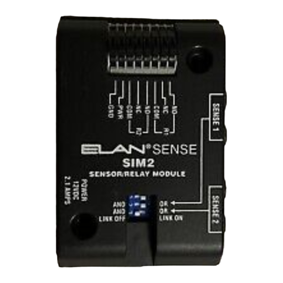
SIM2 INSTALLATION MANUAL ELAN HOME SYSTEMS Introduction The SIM2 Sensor Integration Module is designed to provide dry contact closure or 12 VDC output in response to input ® status from ELAN SENSE Automation Sensors in home automation applications. Capable of being used as a... - Page 5 Relay Connector Sense 1 Inputs (x2) 12VDC Power Input Sense 2 AND/OR Inputs (x2) Logic DIP Switches LINK (x2) DIP Switch Relay Connector Relay 1 Connectors Relay 2 Connectors © ELAN Home Systems 2006 • All rights reserved. Page 3...
-
Page 6: Connections
® Connect an ELAN SENSE Sensor to the SENSE1 and/or SENSE2 ports located on the side of the SIM2. The type of sensor used will depend on the application. Consult the ELANSENSE Installation Manual for details about specific sensor applications. - Page 7 Relay - R1 & R2 There are four basic connection types when confi guring the SIM2. Each of these basic connections can be customized for specifi c applications to provide hundreds of possible uses. Contact Closure - N.O. (Normally Open) Use this method to wire devices that require a simple closed-contact to activate them.
- Page 8 Controlled Device +12 Volt Trigger - N.C. (Normally Closed) Use this method to wire devices that require a 12VDC triggered interruption of power to activate them. Relay Controlled Device Page 6 © ELAN Home Systems 2006 • All rights reserved.
-
Page 9: Dip Switch Settings
ELAN HOME SYSTEMS INSTALLATION MANUAL DIP Switch Settings There are two DIP switches on the SIM2 that provideAND/OR logic functionality for each pair of Sense Inputs, and one DIP switch that links the two Relay Outputs. AND/OR Logic DIP Switches Each Sense Input (SENSE1 and SENSE2) has two ports. -
Page 10: Applications
INSTALLATION MANUAL ELAN HOME SYSTEMS Applications This section provides a few basic examples that illustrate the types of things that the SIM2 is capable of. Many more applications are possible. Basic Home Theater Automation ® This application utilizes an ELAN... - Page 11 Set the SENSE2 DIP switch to AND and the LINK DIP switch to OFF. Screen AUDIO SENSOR VIDEO SENSOR © ELAN Home Systems 2006 • All rights reserved. Page 9...
- Page 12 Home Theater. This application utilizes the LINK feature of the SIM2 to activate both on-board relays . Set the SENSE2 DIP switch to OR and the LINK DIP switch to ON.
- Page 13 Drapes will close. For SENSE2, both the Audio Sensor and Video Sensor must be activated for R1 and R2 to become active. This application utilizes the LINK feature of the SIM2 to activate both on-board relays . Set the SENSE1 DIP switch to OR, the SENSE1 DIP switch to AND, and the LINK DIP switch to ON.
- Page 14 & 7 of the SYSTEM and/or LOCAL ports are shorted. This application allows for specific codes to be sent to devices when sensors connected to the SIM2 are activated. In the drawing below, two Doorbell Sensors are connected to the SIM2.
-
Page 16: Warranty
(2 years) from date of purchase. If within the applicable warranty period above purchaser discovers that such item was not as warranted above and promptly notifi es ELAN in writing, ELAN shall repair or replace the item at the company’s option. This...
Need help?
Do you have a question about the SIM2 and is the answer not in the manual?
Questions and answers