Table of Contents
Advertisement
Advertisement
Table of Contents

Related Manuals for Velodyne VLP-32C


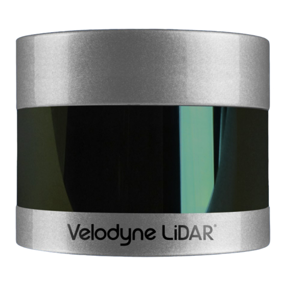
Summary of Contents for Velodyne VLP-32C
- Page 1 VLP-32C User Manual 63-9325 Rev. C...
-
Page 2: Method
Velodyne shall make the final determination as to whether its products are defective. Velodyne 's sole obligation for products failing to comply with this warranty shall be, at its option, to either repair, replace or issue credit for the nonconforming product where, within fourteen (14) days of the expiration of the warranty period, (i) Velodyne has received written notice of any nonconformity;... -
Page 3: Method
• Initial Public Release • ADDED: Laser Power Level reduction based on 3 Channel Groups. • FIXED: Ethernet missing ICMP (Ping) responses. • UPDATED: Beam divergence angles VLP-32C 4.3.0.0 2018-06-15 table. • ADDED: Thermal and ADC fields to the Position Packet. -
Page 4: Table Of Contents
Chapter 1 • About This Manual 1.1 Manual Scope 1.2 Prerequisite Knowledge 1.3 Audience 1.4 Document Conventions Chapter 2 • VLP-32C Overview 2.1 Overview 2.2 Product Models 2.3 Time of Flight 2.4 Data Interpretation Requirements Chapter 3 • Safety Precautions 3.1 Warning and Caution Definitions... - Page 5 5.4 Connections 5.4.1 Interface Box and Cable 5.4.2 Operation Without an Interface Box 5.4.3 Power Chapter 6 • Key Features 6.1 Calibrated Reflectivity 6.2 Laser Return Modes 6.2.1 Single Return Modes: Strongest, Last 6.2.2 Multiple Returns 6.2.3 Dual Return Mode 6.3 Phase Locking Multiple Sensors Chapter 7 •...
- Page 6 9.4 Discreet Point Timing Calculation 9.5 Precision Azimuth Calculation 9.6 Converting PCAP Files to Point Cloud Formats Chapter 10 • Sensor Communication 10.1 Web Interface 10.1.1 Configuration Screen 10.1.1.1 MAC Address 10.1.1.2 Correctly reset MAC Address to Factory MAC Address VLP-32C User Manual...
- Page 7 10.1.2 System Screen 10.1.3 Info Screen 10.1.4 Diagnostics Screen 10.2 Sensor Control with curl 10.2.1 Using curl with Velodyne LiDAR Sensors 10.2.2 curl Command Parameters 10.2.3 Command Line curl Examples 10.2.3.1 Get Diagnostic Data 10.2.3.2 Conversion Formulas 10.2.3.3 Interpret Diagnostic Data 10.2.3.3.1 top:hv...
- Page 8 B.1 Firmware Update Procedure B.1.1 Special Procedure to Update Firmware B.1.2 If An Error Occurs Appendix C • Mechanical Diagrams C.1 Interface Box Mechanical Drawing C.2 VLP-32C Mechanical Drawing Appendix D • Wiring Diagrams D.1 Interface Box Wiring Diagram VLP-32C User Manual...
- Page 9 D.2 Interface Box Schematic Appendix E • VeloView E.1 Features E.2 Install VeloView E.3 Visualize Streaming Sensor Data E.4 Capture Streaming Sensor Data to PCAP File E.5 Replay Captured Sensor Data from PCAP File Appendix F • Laser Pulse F.1 The Semiconductor Laser Diode F.2 Laser Patterns F.2.1 Laser Spot Pattern F.2.2 Laser Scan Pattern...
- Page 10 J.2 Network Considerations J.2.1 Throughput Requirements J.2.2 Single Sensor Transmitting to a Broadcast Address J.2.3 Multiple Sensors in the Same Network J.2.3.1 Multiple Sensors Transmitting to a Broadcast Address J.2.3.2 Multiple Sensors Transmitting to a Specific Address VLP-32C User Manual...
- Page 11 Table 7-3 Post-NMEA Version 2.3 Message Format Table 8-1 Rotation Speed vs Resolution Table 9-1 Factory Byte Values Table 9-2 VLP-32C Data Order in Data Block Table 9-3 Position Packet Structure Field Offsets Table 9-4 PPS Status Byte Values Table 9-5 VLP-32C's Lasers Fire in Pairs...
- Page 12 Figure 7-10 Inverted Signal from UART (correct polarity) Figure 8-1 Firing Sequence Timing Figure 8-2 Point Density Example Figure 9-1 VLP-32C Sensor Coordinate System Figure 9-2 VLP-32 Single Return Mode Data Structure Figure 9-3 VLP-32 Dual Return Mode Data Structure...
- Page 13 Figure B-6 Finalize Firmware Update Figure B-7 Verify Firmware Versions Figure C-1 Interface Box Mechanical Drawing 50-6001 Rev A Figure C-2 VLP-32C Mechanical Drawing 86-0130 Rev 1 Figure D-1 Interface Box Wiring Diagram 86-0107A Figure D-2 Interface Box Schematic 69-8230A...
- Page 14 Figure H-4 Fore and Aft Sensor Phase Offset Figure H-5 Sensor Data Shadows Figure J-1 Sensor Network Settings Figure J-2 Single Sensor Broadcasting on a Simple Network Figure J-3 Multiple Sensors - Improper Network Setup Figure J-4 Multiple Sensors - Proper Network Setup VLP-32C User Manual...
- Page 15 List of Equations Equation 8-1 Azimuth Resolution at 600 RPM Equation 10-1 Standard Voltage Conversion Equation 10-2 Standard Current Conversion Equation 10-3 Standard Temperature Conversion Equation F-1 Gap Between Scan Lines Equation H-1 Arc of Shadow...
-
Page 16: Chapter 1 • About This Manual
1.1 Manual Scope This manual provides descriptions and procedures supporting the installation, verification, operation, and diagnostic eval- uation of the VLP-32 "Ultra Puck" family of Velodyne LiDAR sensors. 1.2 Prerequisite Knowledge This manual is written with the premise that the user has some basic engineering experience and general understanding of LiDAR technology. - Page 17 Note: Notes such as this indicate important information. They call attention to an operating procedure or practice which may enhance user interaction with the product. Notes may also be used to prevent information loss or product damage. Chapter 1 • About This Manual...
-
Page 18: Figure 2-1 Example 3D Sensing System
2.4 Data Interpretation Requirements 2.1 Overview The VLP-32C sensor uses 32 infra-red (IR) lasers paired with IR detectors to measure distances to objects. The device is mounted securely within a compact, weather-resistant housing. The assembly of laser/detector pairs spins rapidly within its fixed housing to scan the surrounding environment, firing each laser approximately 18,000 times per second, providing, in real-time, a rich set of 3D point data. -
Page 19: Chapter 2 • Vlp-32C Overview 2.1 Overview
For more software details, see Converting PCAP Files to Point Cloud Formats on page 69 Note: Click the following link to view a list of Velodyne system integrators who can sell you imaging software or a complete system: http://velodyneLiDAR.com/integrators.php. Chapter 2 • VLP-32C Overview... -
Page 20: Chapter 3 • Safety Precautions
IMPORTANT: Read all installations instructions before powering up the sensor. Note: The VLP-32C sensor is not field serviceable. For servicing and repair, the equipment must be completely shut off, removed, packaged carefully, and shipped back to the manufacturer's facility with a completed RMA Form. See... -
Page 21: Figure 3-1 Class 1 Laser
Figure 3-1 Class 1 Laser Note: The VLP-32C sensor is a CLASS 1 LASER PRODUCT. The product fulfills the requirements of IEC 60825-1:2014 (Safety of Laser Products). There are no controls or adjustments on the sensor itself that are user accessible. -
Page 22: Chapter 4 • Unboxing & Verification
Ensure all the components are present: VLP-32C sensor in a protective shroud, with a fixed 3.0 m data/power cable terminated inside its Interface Box AC/DC power adapter and 1.8 m AC power cord (once assembled, this is the power cord) 1.0 m Ethernet cable... -
Page 23: Network Setup In Isolation
Note: Due to the large volume of data produced by the sensor when scanning, users are cautioned against connecting it to a corporate network. 1. Unpack the sensor and its accessories, and place them on a workbench or desk. Ensure the sensor is upright with clear space around it. -
Page 24: Access Sensor's Web Interface
1. Plug the Ethernet cable into the computer and then plug its other end into the Ethernet port on the sensor’s Inter- face Box. Figure 4-2 below shows the Interface Box, its external ports, internal sensor terminal, and fuse. Figure 4-2 Interface Box (power and data connections) VLP-32C User Manual... -
Page 25: Figure 4-3 Sample Web Interface Main Configuration Screen
2. Connect power to the sensor’s Interface Box. When power is applied, two green LEDs in the Interface Box light up. The sensor begins scanning its environment and transmitting data approximately 30 seconds after power up. 3. On the computer, point a browser to http://192.168.1.201. 4. -
Page 26: Visualize Live Sensor Data With Veloview
Now that the computer can access the sensor’s Web Interface, it’s time to get a first look at the sensor’s data. Note: VeloView is an open source visualization and recording application tailored for Velodyne LiDAR sensors. Other visualization software (e.g. ROS, DSR and PCL) can perform similar functions and may be used instead. -
Page 27: Veloview Operation
4.2.3.1 VeloView Operation 1. Power-up the sensor. 2. Start the VeloView application. 3. Click on File->Open and select Sensor Stream ( Figure 4-4 below Figure 4-4 VeloView Open Sensor Stream Figure 4-5 below 4. The Sensor Configuration dialog will appear ( ). -
Page 28: Figure 4-6 Veloview Sensor Stream Display
Figure 4-6 VeloView Sensor Stream Display Above is an example of a VeloView screen in an office, workbench or lab scenario. VLP-32C User Manual... -
Page 29: Chapter 5 • Installation & Integration
Chapter 5 • Installation & Integration This chapter provides important information for integrating the VLP-32C sensor into your application environment. 5.1 Overview 5.2 Mounting 5.3 Encapsulation, Solar Hats, and Ventilation 5.4 Connections 5.4.1 Interface Box and Cable 5.4.2 Operation Without an Interface Box 5.4.3 Power... -
Page 30: Encapsulation, Solar Hats, And Ventilation
The VLP-32C generates a moderate amount of heat during normal operation. Strategies for managing heat in hot weather include employing a "thermal hat," exposing the sensor to moving air, and drawing heat from the sensor with a heat sink (e.g. -
Page 31: Interface Box And Cable
Interface Box Signals on page 40 5.4.2 Operation Without an Interface Box The VLP-32C's Interface Box is a convenience, but it also adds bulk. The sensor may be ordered and used without the Interface Box to accommodate the needs of the user. Contact Velodyne Sales for details (i.e. -
Page 32: Chapter 6 • Key Features
(e.g. road signs, license plates) in the high range. A retroreflector reflects light back to its source with a minimum of scattering. The VLP-32C provides its own light, with neg- ligible separation between transmitting laser and receiving detector, so retroreflecting surfaces pop with reflected IR light compared to diffuse reflectors that tend to scatter reflected energy. -
Page 33: Multiple Returns
The VLP-32C analyzes multiple returns and reports either the strongest return, the last return, or both returns, depending on the laser return mode setting. If the setting is Strongest and a pulse produces multiple returns, only the strongest reflec- tion results in a measurement. -
Page 34: Figure 6-2 Dual Return With Last And Strongest Returns
The majority of the beam hits the far wall and is (in this case) the strongest return. It's entirely possible, however, that the far wall might be far enough away that despite reflecting the majority of the beam, the return from the near wall would be the strongest return. VLP-32C User Manual... -
Page 35: Figure 6-3 Dual Return With Second Strongest Return
Figure 6-3 Dual Return with Second Strongest Return It's also possible that a small portion of the beam clips a retro-reflector and returns more energy than the majority of the beam, as in Figure 6-4 on the next page Chapter 6 • Key Features... -
Page 36: Figure 6-4 Dual Return With Far Retro-Reflector
6-5 on the facing page indicates a sample response when the laser pulse initially hits the upper canopy, penetrates it, and eventually hits the ground, producing multiple returns. Which laser return mode would be best in this situation? VLP-32C User Manual... -
Page 37: Phase Locking Multiple Sensors
6.3 Phase Locking Multiple Sensors When using multiple Velodyne LiDAR sensors in proximity to one another, users may observe interference between them due to one sensor picking up a reflection intended for another. To minimize this interference, the sensor provides a phase- locking feature that enables the user to control where the laser firings overlap. -
Page 38: Figure 6-6 Phase Locking Example
Figure 6-6 above indicate the firing direction of the sensor's laser at the moment it receives the rising edge of the PPS signal. Additional information for phase locking multiple sensors is located in Phase Lock on page 125 VLP-32C User Manual... -
Page 39: Chapter 7 • Sensor Inputs
Chapter 7 • Sensor Inputs This chapter covers sensor input requirements and functionality, including power, PPS, and Ethernet. It also covers scen- arios for obtaining GPS input. 7.1 Power Requirements 7.2 Interface Box Signals 7.3 Ethernet Interface 7.4 GPS, Pulse Per Second (PPS) and NMEA Sentence 7.4.1 GPS Input Signals 7.4.2 Electrical Requirements 7.4.3 Timing and Polarity Requirements... -
Page 40: Interface Box Signals
Signal Specifications Signal Input/Output Black Ground Input Power Input Yellow GPS Sync Pulse Input White GPS Serial Receive Input Light Orange Ethernet TX+ Output Orange Ethernet TX- Output Light Blue Ethernet RX+ Input Blue Ethernet RX- Input VLP-32C User Manual... -
Page 41: Ethernet Interface
The ground signal from the GPS/INS is connected to the sensor’s Interface Box via the screw terminal labeled: “GROUND.” Note: You can use the provided GPS port on the Interface Box if using the Velodyne GPS Receiver (P/N 80- GPS18LVC). -
Page 42: Figure 7-3 Pps Signal Closely Followed By Nmea Gprmc Message
Figure 7-3 PPS Signal Closely Followed by NMEA GPRMC Message Figure 7-4 PPS Signal Followed 600 ms later by NMEA GPRMC Message VLP-32C User Manual... -
Page 43: Figure 7-5 Rs-232 Example Transmission
The serial connection for the NMEA message follows the RS232 standard. The interface is capable of handling voltages between ±15 VDC. Low voltages are marks and represent a logical 1. High voltages are spaces and represent a logical 0. The serial line idle state (MARK) is a low voltage indicating a logical 1. When the start bit is asserted, the positive voltage will be asserted representing a logical 0. -
Page 44: Gps Connection Scenarios
There are three common connection scenarios: connecting to a sensor from a Velodyne-supplied Garmin 18x LVC GPS receiver, connecting to it from a computer's serial port, and connecting directly from a microcomputer’s UART. -
Page 45: Figure 7-7 Garmin Gprmc Message
The receiver plugs directly into the Interface Box’s GPS port and is used to synchronize your sensor's timestamp with pre- cision GPS time. The signals from the Garmin receiver will be similar to those shown in Figure 7-7 below where the signal is normally low and zeros are represented by the high voltage. -
Page 46: Connecting To A Computer's Serial Port
Raspberry Pi UART output and Figure 7-10 on the facing page shows the same output inverted into a signal compatible with your Velodyne sensor. Figure 7-9 Signal Directly from UART (incorrect polarity) VLP-32C User Manual... -
Page 47: Nmea Message Formats
Figure 7-10 Inverted Signal from UART (correct polarity) 7.4.5 NMEA Message Formats GPGGA may be substituted in place of GPRMC. The sensor accepts both pre- and post-NMEA version 2.3 sentence structures. The difference is that in version 2.3 a Fix Mode Indicator field was added after Magnetic Variation and before the Checksum. -
Page 48: Nmea Version 2.3 Message Format
Track made good (degrees True) 230394 23rd of March 1994 003.1,W Magnetic Variation Fix Mode Indicator: A = Autonomous, D = Differential, E = Estimated, N = Not valid, S = Simulator. Sometimes there can be a null value as well. VLP-32C User Manual... -
Page 49: Accepting Nmea Messages Via Ethernet
Value Description * followed by 2-byte Checksum Note: The Receiver Status (aka Validity) field in the GPRMC message ('A' or 'V') should be checked to ensure the GPS receiver is actively positioning and is providing trustworthy UTC (Coordinated Universal Time) and position updates. If status is Void, which usually occurs when the GPS receiver is searching for satellites, GPS position should be ignored. -
Page 50: Chapter 8 • Sensor Operation
8.2.1 Data Packet Rate There are 12 firing cycles in a data packet. 12 x 55.296 μs = 0.663552 ms is the accumulation delay per packet. 1 packet/0.663552 ms = 1507 packets/second 1248 bytes/packet * 1507 packets/second = 1880736 bytes/second VLP-32C User Manual... -
Page 51: Position Packet Rate
1248 bytes/packet * 6253.9 packets/second = 7804867.2 bytes/second 8.2.2 Position Packet Rate Position packets arrive at approximately 1/14th the rate of data packets. 554 bytes/packet * 1507 packets/second / 14 = 59634 bytes/second 8.2.3 Total Packet Rate Summing yields 1940370 bytes/second for single return mode. Dual return mode doubles the data rate but not the position packet rate: (2 * 1880736 bytes/second) + 59634 bytes/second = 3821106 bytes/second 8.2.4 Laser Measurements Per Second... -
Page 52: Rotation Speed Fluctuation And Point Density
. On the left is a single frame of data. On the right is the same frame and the nine preceding frames overlaid on each other. You can see how the azimuth gaps are filled. Figure 8-2 Point Density Example VLP-32C User Manual... -
Page 53: Chapter 9 • Sensor Data
Sensor data origin (0,0,0) is 37.34 mm above the sensor base, on the center axis, as shown in Figure 9-1 on the next page (see the side and top views), which also shows the sensor’s frame of reference. See also VLP-32C Mechanical Drawing on page 104 9.2 Calculating X,Y,Z Coordinates from Collected Spherical Data A computation is necessary to convert the spherical data (radius r, elevation ω, azimuth α) from the sensor to Cartesian... -
Page 54: Packet Types And Definitions
Figure 9-1 VLP-32C Sensor Coordinate System 9.3 Packet Types and Definitions There are two types of packets generated by the sensor: Data packets and Position packets. Position packets are some- times referred to as telemetry packets, or GPS packets. Data packets contain the 3D data measured by the sensor as well as the calibrated reflectivity of the surface from which the light pulse was returned. -
Page 55: Firing Sequence
Laser recharge time is included. A firing sequence is sometimes referred to as a firing group. A firing sequence is not allowed to span multiple data packets. It takes 55.296 μs to fire all 32 lasers in a VLP-32C and recharge. VLP-32C sensors fire their lasers in pairs. 9.3.1.2 Laser Channel A laser channel is a single 903 nm laser emitter and detector pair. -
Page 56: Factory Bytes
A data packet is 1248 bytes long and sent via a UDP packet on port 2368. The data packet is comprised of 42 bytes of pro- tocol header, twelve Data Blocks, a four-byte timestamp, and two factory bytes. There are two formats for the data packet: VLP-32C User Manual... -
Page 57: Figure 9-2 Vlp-32 Single Return Mode Data Structure
Single Return Mode (either Strongest or Last) Dual Return Mode Laser Return Modes on page 32 for an illustration of what Strongest, Last, and Dual mean in this context. The packet data structure for Single Return Mode is shown in Figure 9-2 below . -
Page 58: Table 9-2 Vlp-32C Data Order In Data Block
Figure 9-3 VLP-32 Dual Return Mode Data Structure Table 9-2 VLP-32C Data Order in Data Block Laser ID Elevation Angle (°) Azimuth Offset (δ) -4.2 -1.667 -15.639 -1.4 -11.31 -1.4 -0.667 -8.843 -1.4 -7.254 0.333 -4.2 -0.333 -6.148 -1.4 -5.333 1.333... -
Page 59: Position Packet Structure
Laser ID Elevation Angle (°) Azimuth Offset (δ) 0.667 -1.4 -4.667 1.667 -4.2 -3.667 -4.2 -3.333 3.333 -1.4 2.333 -2.667 -1.4 -1.4 4.667 -2.333 -4.2 -1.4 10.333 -1.333 -1.4 9.3.3 Position Packet Structure The role of the Position Packet (often called the Telemetry Packet) is to provide a copy of the most recent, supported NMEA sentence received from an external GPS/INS/IMU source as well as the Pulse Per Second status, plus a time stamp representing when the position packet was assembled, and possibly other related info. - Page 60 Temperature of unit (bottom board) at power up power up 0xCE- NMEA sentence GPRMC or GPGGA 0x14D 0x14E- Reserved unused (null bytes) 0x1FF The GPRMC sentence is terminated with CR/LF and padded to end of payload with null bytes. VLP-32C User Manual...
-
Page 61: Table 9-4 Pps Status Byte Values
Table 9-4 PPS Status Byte Values Value Description No PPS detected Synchronizing to PPS PPS Locked Error A position packet is shown in the figure below. Packet offsets are on the left, raw data bytes in hex are in the center, and the ASCII interpretation is on the right. -
Page 62: Discreet Point Timing Calculation
(16 × 2.304 μs) + 18.43 μs = 55.296 μs. Figure 9-5 Firing Sequence Timing VLP-32C lasers are fired in pairs at widely separated angles to minimize IR crosstalk. The sequence of firings is specified in Table 9-5 below . - Page 63 Firing Elevation Elevation Laser ID Laser ID Order Angle (°) Angle (°) -3.667 -3.333 3.333 2.333 -2.667 4.667 -2.333 10.333 -1.333 To calculate the exact time, in microseconds, of each data point in a packet, first number the points in the firing sequence from 0 to 31.
-
Page 64: Figure 9-6 Example Data Point Timing Calculation
TimeOffset = timing_offsets[15][23] ExactPointTime = Timestamp + TimeOffset ExactPointTime = 45,231,878 + 1,306.368 µs ExactPointTime = 45,233,184.368 µs Figure 9-6 below shows the timing calculation for a few data points. Figure 9-6 Example Data Point Timing Calculation VLP-32C User Manual... -
Page 65: Figure 9-7 Single Return Mode Timing Offsets (In Μs)
Figure 9-7 Single Return Mode Timing Offsets (in µs) Chapter 9 • Sensor Data... -
Page 66: Precision Azimuth Calculation
Laser ids are listed in four columns according to where they are situated in the VLP-32C laser firing map. Table 9-6 VLP-32C Azimuth Offsets by Elevation Azimuth Offsets (δ) Elevation... - Page 67 Azimuth Offsets (δ) Elevation Col 1 Col 2 Col 3 Col 4 Angle (°) +4.2° +1.4° -1.4° -4.2° 4.667 3.333 2.333 1.667 1.333 1.000 0.667 0.333 0.000 -0.333 -0.667 -1.000 -1.333 -1.667 -2.000 -2.333 -2.667 -3.000 -3.333 -3.667 -4.000 -4.667 -5.333 -6.148 -7.254...
- Page 68 If you examine the XML file on the thumb drive that came with your sensor, you’ll notice the horizontal offsets (rotCorrection_) are of opposite polarity to those shown in Table 9-6 on page 66 . This is to accommodate the cal- culations in VeloView. VLP-32C User Manual...
-
Page 69: Converting Pcap Files To Point Cloud Formats
9.6 Converting PCAP Files to Point Cloud Formats Converting a packet capture (pcap) file of Velodyne LiDAR data to a LAS, LAZ, XYZ, PLY, or other point cloud file format can be a non-trivial process. The data provided by the sensor in the pcap file is measured relative to the sensor’s reference frame - the sensor’s internal three dimensional coordinate system which moves with the sensor. -
Page 70: Chapter 10 • Sensor Communication
10.1.1 Configuration Screen 10.1.2 System Screen 10.1.3 Info Screen 10.1.4 Diagnostics Screen 10.2 Sensor Control with curl 10.2.1 Using curl with Velodyne LiDAR Sensors 10.2.2 curl Command Parameters 10.2.3 Command Line curl Examples 10.2.4 curl Example using Python 10.1 Web Interface The easiest way to control a sensor’s operation is through its Web Interface. -
Page 71: Configuration Screen
10.1.1 Configuration Screen Figure 10-1 VLP-32C Configuration Screen Table 10-1 Configuration Screen Functionality and Features Function Description Default Laser Turns the sensor's laser ON or OFF. ON/OFF Strongest — Sensor provides only the strongest detected return. Last — Sensor provides only the last (temporally) detected return. - Page 72 IPv4 Address — Sensor IP address as specified by the user. 255.255.255.0 (Sensor) Mask — Sensor subnet mask as specified by the user. 192.168.1.1 Gateway — Sensor gateway as specified by the user. MAC Address - Sensor MAC address override. Set — Activates changes. VLP-32C User Manual...
-
Page 73: Mac Address
PPS and GPS Qualifier functions. 10.1.1.1 MAC Address The ability to change the sensor's MAC Address was introduced with VLP-32C firmware release 4.1.2.0. It may be advantageous to change the sensor's MAC address for asset management in multi-sensor situations where the MAC address is the closest thing to a hard sensor ID, or as an anti-tracking measure. -
Page 74: System Screen
Once the sensor is done resetting, you may refresh the page and go back to the Configuration Screen. The MAC Address should match the Factory MAC Address. 10.1.2 System Screen Figure 10-2 VLP-32C System Screen Table 10-2 System Screen Functionality and Features Function Description Choose File —... -
Page 75: Info Screen
Table 10-3 Info Screen Functionality and Features Function Description Board — Top or Bottom board information. Mode — State of the Application Watchdog – Velodyne use only. Type — Velodyne Use Only. FPGA (top board) HW Version — Velodyne Use Only. - Page 76 Board — Top or Bottom board information. Mode – Velodyne use only. Type — Velodyne Use Only. FPGA (bottom board) HW Version — Velodyne Use Only. SOPC SYSID — Velodyne Use Only. SW Version — Current operating firmware version. Build — Velodyne Use Only.
-
Page 77: Diagnostics Screen
10.1.4 Diagnostics Screen Figure 10-4 VLP-32C Diagnostics Screen Table 10-4 System Screen Functionality and Features Function Description HV — Velodyne Use Only. A/D TD — Velodyne Use Only. Temp — Circuit board temperature. 5v — Internal voltage status. Top Board (Scaled) 2.5v —... -
Page 78: Sensor Control With Curl
10.2 Sensor Control with curl In addition to the Web Interface, Velodyne LiDAR sensors provide an HTTP interface for programmatic configuration and control. One of the easiest tools to use for this purpose is curl. curl is a command line program freely available on a wide variety of operating systems. -
Page 79: Command Line Curl Examples
Set Field of View by sending a urlencoded key and data pair to http://192.168.1.201/cgi/setting/fov: 1. [start]|[end]=[integer] Set Sensor Address, Destination Port, or Telemetry Port by sending a urlencoded key and data pair to http://192.168.1.201/cgi/setting/host: 1. addr=255.255.255.255 2. dport=2368 3. tport=8309 Network Settings can be set by providing the urlencoded key and data pair to http://192.168.1.201/cgi/setting/net: 1. -
Page 80: Conversion Formulas
The HV field comes from the sensor's top board. It represents the high voltage bias to the APD (Avalanche photodiode). Its operating range is -150.0 V to -132.0 V. To convert the raw value, use Equation 10-1 above then scale the result by subtracting 5.0 and multiplying the result by 101.0. VLP-32C User Manual... -
Page 81: Top:lm20_Temp
Example: hv = 2917 (raw value) (2917 * 5.0) / 4096 = 3.561 101.0 * (3.561 - 5.0) = -145.34 V 10.2.3.3.2 top:lm20_temp This field indicates the temperature of the top board. Its operating range is -25.0° C to 90.0° C. To convert the raw value, use Equation 10-3 on the previous page Example:... -
Page 82: Top:pwr_Raw
This field indicates the temperature of the bottom board. Its operating range is -25.0° C to 90.0° C. To convert the raw value, use Equation 10-3 on page 80 Example: lm20_temp = 1231 (raw value) (1105 * 5.0) / 4096 = 1.503 -1481.96 + SQRT(2.1962E6 + ((1.8639 – 1.503) / 3.88E-6)) = 31.082° C VLP-32C User Manual... - Page 83 10.2.3.3.10 bot:pwr_1_2v This is the bottom board's 1.2 V rail. Its operating range is 1.0 V to 1.4 V. Equation 10-1 on page 80 To convert the raw value, use Example: pwr_1_2v = 992 (raw value) (992 * 5.0) / 4096 = 1.211 V 10.2.3.3.11 bot:pwr_1_25v This is the bottom board's 1.25 V rail.
-
Page 84: Bot:pwr_V_In
Sets the RPM of the motor. Valid integer values range from 300 to 1200, in increments of 60. (If the RPM setting is not evenly divisible by 60, neither motor speed control nor phase lock functions will function properly.) For values 1 VLP-32C User Manual... -
Page 85: Set Field Of View
through 299, the sensor defaults back to 300 RPM. If a value of 0 or less is entered, the sensor motor powers down and the lasers are turned off, as leaving them on with the motor stopped would be an unsafe eye state. This has the same effect as setting the value for the Motor RPM in the Web Interface. -
Page 86: Network Configuration
--data "gateway=192.168.1.2" http://192.168.1.201/cgi/setting/net 10.2.3.18 Set DHCP This determines if the sensor is to rely on a DHCP server for its IP address. This has the same effect as selecting the corresponding radio button for DHCP in the Web Interface. VLP-32C User Manual... -
Page 87: Curl Example Using Python
Take care when turning DHCP ON. Before doing so, ensure a DHCP server on the network is available to provide the sensor with an IP address. If you turn DHCP ON and lose contact with the sensor, follow the Turned DHCP On, Lost Contact With Sensor on page 90 procedure to get it back. - Page 88 'Sensor laser is %s, motor rpm is %s' % \ (status['laser']['state'], status['motor']['rpm']) sensor.close() Typical output looks like the following: http://192.168.1.201/cgi/reset data=reset_system: 204 (OK) http://192.168.1.201/cgi/setting rpm=300: 204 (OK) http://192.168.1.201/cgi/setting laser=on: 204 (OK) Sensor laser is On, motor rpm is 301 VLP-32C User Manual...
-
Page 89: Chapter 11 • Troubleshooting
Chapter 11 • Troubleshooting This section provides detail on how to troubleshoot your sensor, how to request technical assistance, how to have the sensor repaired, and how to replace the fuse in the Interface Box. 11.1 Troubleshooting Process 11.1.1 Turned DHCP On, Lost Contact With Sensor 11.2 Service and Maintenance 11.2.1 Fuse Replacement 11.3 Technical Support... -
Page 90: Turned Dhcp On, Lost Contact With Sensor
Class B IP address that looks like 169.254.x.x. Your computer's IP address will likely be very different (not on the same logical network) resulting in a failure to communicate with the sensor. Perform the following procedure to regain communication with the sensor. VLP-32C User Manual... -
Page 91: Service And Maintenance
On Mac OS and various linuxes, use the ‘arp -a’ command. Velodyne LiDAR sensors respond to ARP. The arp command displays the current IP-to-physical address translation table. If desired, you can narrow it to a specific interface with the ‘-N if_addr’ argument. Look for an address that matches the pattern 169.254.x.x. -
Page 92: Technical Support
If your product was damaged during initial shipping or has failed during or beyond its warranty period, a Return Mer- chandise Authorization (RMA) must be issued prior to shipping the product to Velodyne LiDAR for service. The Return Merchandise Authorization (RMA) form can be downloaded from the Velodyne LiDAR Downloads page at: http://velodyneLiDAR.com/downloads.html. -
Page 93: Appendix A • Sensor Specifications
Sensor Specifications Sensor specifications (including environmental and regulatory specifications) have been moved to product data sheets found on the Velodyne LiDAR web site at this address: http://www.velodynelidar.com/downloads.html#datasheets. For additional information, contact Velodyne LiDAR Sales: http://www.velodynelidar.com/contacts.php. Appendix A • Sensor Specifications... -
Page 94: Appendix B • Firmware Update
This procedure works best with the Chrome browser. 1. Point your browser to the Velodyne Downloads page at http://velodyneLiDAR.com/downloads.html. Figure B-1 Velodyne Downloads Page 2. Click the FIRMWARE icon (on the left) to advance to the Firmware section. Note the latest version available. -
Page 95: Figure B-2 Compare Firmware Versions
Figure B-2 Compare Firmware Versions Note: The firmware image labeled “Failsafe” is the original image programmed into the sensor when it was man- ufactured. It cannot be updated. Appendix B • Firmware Update... -
Page 96: Figure B-3 Select New Firmware Image
8. Using the dialog, locate the new firmware file on your computer and select it. 9. Verify that the correct file for your sensor model has been selected. It must have the ‘.flash’ file extension. 10. Click Update Firmware's Update button to initiate the update process. VLP-32C User Manual... -
Page 97: Figure B-4 Upload New Firmware Image
Figure B-4 Upload New Firmware Image 11. As shown in the figure above, a progress bar indicating the percentage of update completion is displayed. 12. When this first stage of the update is complete, the Firmware Update Complete screen (below) is displayed. But wait, there's more. -
Page 98: Figure B-5 Firmware Update Complete Page
14. A second progress bar is shown. Note: This step should take approximately 70 seconds. If it completes in less than 10 seconds an error occurred. Instead of continuing, perform the If An Error Occurs on page 101 procedure. VLP-32C User Manual... -
Page 99: Figure B-6 Finalize Firmware Update
Figure B-6 Finalize Firmware Update 15. When processing completes, press the Reset System button to finalize the update. The sensor will perform a warm boot. 16. The Configuration screen will be shown when the sensor finishes rebooting. 17. Return to the Info page. Appendix B •... -
Page 100: Special Procedure To Update Firmware
3. Press Update to update the bottom board. 4. Wait a bit. 5. You will eventually see another screen entitled, “Firmware Upload Complete.” 6. Do not press the Process Firmware Update button to flash the top board. *This is where the process deviates VLP-32C User Manual... -
Page 101: If An Error Occurs
from the normal procedure.* 7. Instead, reset the sensor, either by pressing the Reset System button or cycling power to the sensor. 8. The sensor boots up. At this point, you do not have to run the update process for the bottom board again. Go to the System tab and click on the Update button associated with 'Update Firmware'. -
Page 102: Appendix C • Mechanical Diagrams
Appendix C • Mechanical Diagrams This appendix provides technical drawings and diagrams of mechanical assemblies. High resolution versions may be accessed on the Velodyne LiDAR web site. C.1 Interface Box Mechanical Drawing C.2 VLP-32C Mechanical Drawing VLP-32C User Manual... -
Page 103: Interface Box Mechanical Drawing
C.1 Interface Box Mechanical Drawing Figure C-1 Interface Box Mechanical Drawing 50-6001 Rev A Appendix C • Mechanical Diagrams... -
Page 104: Vlp-32C Mechanical Drawing
C.2 VLP-32C Mechanical Drawing Figure C-2 VLP-32C Mechanical Drawing 86-0130 Rev 1 VLP-32C User Manual... -
Page 105: Appendix D • Wiring Diagrams
D.1 Interface Box Wiring Diagram D.2 Interface Box Schematic Note: The VLP-16 wiring diagram is specified below because the wiring leading to the Interface Box for the VLP-32C is essentially identical to that of the VLP-16. Appendix D • Wiring Diagrams... -
Page 106: Interface Box Wiring Diagram
D.1 Interface Box Wiring Diagram Figure D-1 Interface Box Wiring Diagram 86-0107A VLP-32C User Manual... -
Page 107: Interface Box Schematic
D.2 Interface Box Schematic Figure D-2 Interface Box Schematic 69-8230A Appendix D • Wiring Diagrams... -
Page 108: Appendix E • Veloview
E.5 Replay Captured Sensor Data from PCAP File E.1 Features VeloView provides real-time visualization of 3D LiDAR data from Velodyne LiDAR sensors. VeloView can also playback pre-recorded data stored in “pcap” (Packet Capture) files. Note: VeloView does not support .pcapng files. -
Page 109: Install Veloview
Installers for VeloView for Windows (32-bit and 64-bit) and Macintosh computers can be found on the USB stick included with your sensor. Links to the latest installers can be found on the Velodyne web site. You can install VeloView from the USB stick or follow the steps below to install from the web site. -
Page 110: Figure E-2 Veloview Select Sensor Calibration
Figure E-2 VeloView Select Sensor Calibration 5. VeloView begins displaying the sensor data stream. VLP-32C User Manual... -
Page 111: Capture Streaming Sensor Data To Pcap File
Figure E-3 VeloView Sensor Stream Display The stream can be paused by pressing the Play button. Press it again to resume streaming. E.4 Capture Streaming Sensor Data to PCAP File 1. Click the Record button. Appendix E • VeloView... -
Page 112: Replay Captured Sensor Data From Pcap File
VeloView begins writing packets to your pcap file. 3. Recording will continue until the Record button is clicked again, which stops the recording and closes the pcap file. Note: Velodyne LiDAR sensors generate a lot of data. (See Sensor Specifications on page 93 for data rates.) The pcap... -
Page 113: Figure E-5 Veloview Open Capture File
Figure E-5 VeloView Open Capture File 2. An Open File dialog will pop up. Navigate to a pcap file, select it, and click the Open button. The Sensor Con- figuration dialog will pop-up. 3. Select your sensor type and click OK. VeloView should display frame 0. -
Page 114: Figure E-7 Veloview Spreadsheet Tool
Drag column headers left or right to reorder them. Sort the table by clicking column headers. And you can make the table itself wider by dragging the table’s sides left or right. Make Points_m_XYZ wider to expose the XYZ points themselves. Figure E-8 VeloView Data Point Table 7. Click Show only selected elements. VLP-32C User Manual... -
Page 115: Figure E-9 Veloview Show Only Selected Elements
Figure E-9 VeloView Show Only Selected Elements Since no points are selected yet, the table will be empty. 8. Click the Select All Points tool. This turns your mouse into a point selection tool. Figure E-10 VeloView Select All Points 9. -
Page 116: Figure E-11 Veloview List Selected Points
Azimuth is in hundredths of a degree. Distances are with respect to the sensor’s origin. At any point you can save a subset of data frames by doing File > Save As > Select Frames. VLP-32C User Manual... -
Page 117: Appendix F • Laser Pulse
Appendix F • Laser Pulse This section provides details on your sensor’s laser diodes, the laser pulse and scan patterns, and certain beam char- acteristics of the laser pulses. F.1 The Semiconductor Laser Diode F.2 Laser Patterns F.2.1 Laser Spot Pattern F.2.2 Laser Scan Pattern F.2.3 Beam Divergence F.1 The Semiconductor Laser Diode... -
Page 118: Laser Patterns
Read more about that in Beam Divergence on the facing page Figure F-2 Laser Spot Shape F.2.2 Laser Scan Pattern The gap between scan lines can be calculated with the following equation: Equation F-1 Gap Between Scan Lines VLP-32C User Manual... -
Page 119: Beam Divergence
Figure F-3 Laser Spots on a Wall Photo of sensor laser pattern reflecting off of a flat target a short distance away. F.2.3 Beam Divergence As a laser pulse propagates outward from the sensor the cross-section of the laser beam describing the path of the pulse gradually, steadily grows larger. -
Page 120: Table F-1 Vlp-32C Beam Divergence
VLP-32C beam divergence on the horizontal axis (i.e. along the direction of the laser scan) differs from beam divergence on the vertical axis (transverse to the scan) by roughly a factor of two. Table F-1 VLP-32C Beam Divergence Horizontal Beam Divergence Vertical Beam Divergence 3.43 mrad (0.1965245 deg) -
Page 121: Appendix G • Time Synchronization
Appendix G • Time Synchronization This section provides a detailed discussion of the GPS Qualifier and PPS Qualifier functions. G.1 Introduction G.2 Background G.3 PPS Qualifier G.3.1 Require GPS Receiver Valid G.3.2 Require PPS Lock G.3.3 Delay G.4 GPS Qualifier G.5 Application G.6 Logic Tables G.1 Introduction... -
Page 122: Pps Qualifier
PPS signal regardless of GPS receiver satellite status. G.3.2 Require PPS Lock This setting determines the manner in which the sensor validates the PPS signal prior to adjusting the internal sub-second counter to the rising edge of that PPS signal. VLP-32C User Manual... -
Page 123: Delay
If Require PPS Lock is set to On the sensor utilizes the value in the Delay field to determine the validity of a PPS signal prior to synchronizing its internal sub-second counter to the rising edge of a PPS signal. If Require PPS Lock is set to Off the sensor ignores the value in the Delay field and the sensor uses a rolling win- dow of 2 cycles before the PPS signal may be considered valid and then used as a time reference by the sensor. -
Page 124: Figure G-4 Minutes And Seconds Counter Behavior
Figure G-4 Minutes and Seconds Counter Behavior Note: If no NMEA sentence is provided, the Minutes and Seconds counter is driven by the rollover of the sub-seconds counter. VLP-32C User Manual... -
Page 125: Appendix H • Phase Lock
When using multiple sensors close to one another (e.g. mounted on top of a vehicle), occasional interference patterns may appear in the sensor data. Velodyne provides firing controls to minimize this interference by controlling where data is gathered. The sensors can then be configured to ignore the data containing the interference. -
Page 126: Application Scenarios
H.1.2 Application Scenarios When setting the phase lock offset for two or more sensors, Velodyne recommends the sensors be configured to fire at each other. This is the optimal configuration for minimizing interference because the location of the interference is under user control. -
Page 127: Figure H-3 Right And Left Sensor Phase Offset
Figure H-3 Right and Left Sensor Phase Offset When sensors are placed on the roof in the fore and aft positions, the phase offsets are set to 180° and 0° as shown in Fig- ure H-4 below Figure H-4 Fore and Aft Sensor Phase Offset In both scenarios the two sensors create data shadows behind each other. -
Page 128: Field Of View
Then, using each sensor's Web Interface or curl commands (or equivalent programmatic commands), configure the sensor's horizontal FOV start and end angles. See Configuration Screen on page 71 Set Field of View on page 85 more. VLP-32C User Manual... -
Page 129: Appendix I • Sensor Care
Appendix I • Sensor Care To accurately sense its environment, the VLP-32C sensor should be kept clean, especially its ring lens. This section lists various approved cleaning methods, but it is important to use the correct method. Start with Determine Method of Cleaning the Ring Lens below I.1 Cleaning the Sensor... -
Page 130: Cleaning Tips
If the first five characters of the serial number are between AE001 and AE229, clean the sensor using Method 1 below. If the first five characters of the serial number are AE230 or greater, or if the sensor was serviced by Velodyne LiDAR after August 17th, 2015, use either Method 2 or 3 below. -
Page 131: Cleaning Non-Optical Sensor Surfaces
1. Spray NACL Precision Optics Cleaner solution onto a clean, dry microfiber cloth. 2. Gently wipe the VLP-32C’s ring lens along the curve of the sensor, not top-to-bottom. I.2 Cleaning Non-Optical Sensor Surfaces Clean non-optical sensor surfaces with soapy water and a clean microfiber cloth. Follow the Cleaning Tips above. Avoid getting electronic components, such as connectors and the PCB in the Interface Box, if present, wet. -
Page 132: Appendix J • Network Configuration
Each sensor’s IP address is set at the factory to 192.168.1.201. By default, the sensor sends UDP data packets to broadcast address 255.255.255.255. Note: Each sensor has a unique MAC Address and Serial Number set at the factory by Velodyne LiDAR that cannot be changed. -
Page 133: Network Considerations
7. Enter the subnet mask: 255.255.255.0 When using a Windows OS based computer, you can press the TAB key and the subnet mask automatically pop- ulates with the 255.255.255.0 value. 8. Click OK. 9. We recommend disabling any firewall software the computer may have running. 10. -
Page 134: Single Sensor Transmitting To A Broadcast Address
Note: Each sensor must have its own, unique IP address in a given network. When using multiple Velodyne LiDAR sensors in a network it is imperative that you set each sensor's destination IP address to a specific, non-broadcast IP address. However, two or more sensors may share the same destination address. -
Page 135: Multiple Sensors Transmitting To A Specific Address
Figure J-3 Multiple Sensors - Improper Network Setup J.2.3.2 Multiple Sensors Transmitting to a Specific Address The solution is to configure each sensor on such a network to transmit their data to a non-broadcast address. If every sensor in the same network transmits packets to a specific, non-broadcast, destination address (doesn’t have to be the same one), as illustrated in Figure J-4 below , the other sensors will not suffer unnecessary network overhead. - Page 136 Corporate Headquarters: Velodyne LiDAR, Inc. 5521 Hellyer Ave San Jose, CA 95138 U.S.A. www.VelodyneLiDAR.com Phone +1 408-465-2800 Fax +1 408-779-9227 Email lidar@velodyne.com VLP-32C User Manual 63-9325 Rev. C Updated 2019-02-07...
Need help?
Do you have a question about the VLP-32C and is the answer not in the manual?
Questions and answers