
Related Manuals for Velodyne HDL-64E


Summary of Contents for Velodyne HDL-64E
- Page 1 - 64E ™ U S E R ’ S M A N U A L H i g h D e f i n i t i o n L i d a r ™ S e n s o r...
- Page 2 C a u t i o n INVISIBLE LASER RADIATION DO NOT VIEW DIRECTLY WITH OPTICAL INSTRUMENTS CLASS 1M LASER PRODUCT w w w . v e l o d y n e . c o m HDL-64E User’s Manual...
-
Page 3: Table Of Contents
Appendix C — Digital Sensor Recorder (DSR) .......13 w w w . v e l o d y n e . c o m HDL-64E User’s Manual... -
Page 4: Introduction
I n t r o d u c t i o n Congratulations on your purchase of a Velodyne HDL-64E High Definition Lidar Sensor. This product represents a breakthrough in sensing technology by providing exponentially more information about the surrounding environment than previously possible. -
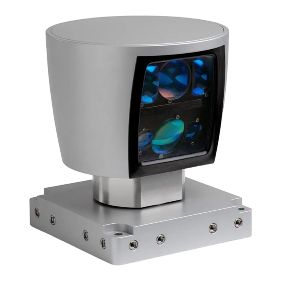
Page 5: Principles Of Operation
Housing Figure 1. HDL-64E design overview. The HDL-64E employs a direct drive motor system — there are no belts or chains in the drive train. w w w . v e l o d y n e . c o m... -
Page 6: Installation Overview
F r o n t / B a c k M o u n t i n g The HDL-64E base provides two mounting options: side mount and top mount. See Figure 2 for front/back mounting options, Figure 3 for side/side mounting, and Figure 4 for top mounting instructions. - Page 7 S i d e M o u n t i n g Mounting Base Figure 3. Side/side HDL mounting illustration. w w w . v e l o d y n e . c o m HDL-64E User’s Manual...
- Page 8 G-forces. The HDL-64E is weatherproofed to withstand wind, rain, and other adverse weather conditions. The spinning nature of the HDL-64E helps the unit shed excess water from the front window that could hamper performance. w w w . v e l o d y n e . c o m...
-
Page 9: Wiring
Power. Connect the red and black wires to vehicle power. Be sure red is positive polarity. THE HDL-64E IS RATED ONLY FOR 12 VOLTS. Any voltage applied over 16 volts could damage the unit. Expect the unit to draw 4-6 amps during normal usage. -
Page 10: Correction Angles
C o r r e c t i o n A n g l e s Each HDL-64E laser is fixed with respect to vertical angle and offset to the rotational index data provided in each packet. For each data point issued by the HDL-64E, rotational and horizontal correction factors must be applied to determine the point’s location in 3-D space referred to by... -
Page 11: Controlling The Spin Rate
C o n t r o l l i n g t h e S p i n R a t e The HDL-64E can spin at rates ranging from 300 RPM (5 Hz) to 900 RPM (15 Hz). The default is 600 RPM (10 Hz). -
Page 12: Troubleshooting
S e r v i c e a n d M a i n t e n a n c e There are no user service or maintenance requirements or procedures for the Velodyne HDL-64E. For service or maintenance, please contact Velodyne at (408) 465-2800, or log on to our website at www.velodyne.com/lidar. -
Page 13: Specifications
• 10" tall cylinder of 8" OD radius • 300 RPM - 900 RPM spin rate (user selectable) • 100 MBPS UDP Ethernet packets Output: w w w . v e l o d y n e . c o m HDL-64E User’s Manual... -
Page 14: Appendix A - Connector Wiring Diagram
A p p e n d i x A - C o n n e c t o r W i r i n g D i a g r a m w w w . v e l o d y n e . c o m HDL-64E User’s Manual... -
Page 15: Appendix B - Angular Resolution
0.1728 0.3456 N o t e s : The HDL-64E generates 1 million points per second • The lower block reports 250,000 points • The upper block reports 750,000 points There are three upper block packets then one lower block packet reported, then the pattern repeats. -
Page 16: Appendix C - Digital Sensor Recorder (Dsr)
L i v e P l a y b a c k : For live playback, first secure and power up the HDL-64E sensor so that it is spinning. Connect the RJ45 Ethernet connector to your host computer’s network connection. You may wish to utilize auto DNS settings for your computers network configuration. - Page 17 10 meter increments from the sensor, which is depicted on the screen by a white circle. w w w . v e l o d y n e . c o m HDL-64E User’s Manual...
- Page 18 This data should also be used in any other program using the data generated by the HDL-64E. To i n t e g r a t e t h e d b . X M L f i l e i n t o t h e D S R p r o g r a m , —...
- Page 19 Figure 6. Calibration values as seen in DSR/File/Properties w w w . v e l o d y n e . c o m HDL-64E User’s Manual...
- Page 20 D S R M o u s e C o n t r o l s Rotational: Left Button/Move Slide: Right Button/Move Zoom: Scroll forward = Zoom In Scroll backward = Zoom Out w w w . v e l o d y n e . c o m HDL-64E User’s Manual...
- Page 21 Service E-mail: service@velodyne.com Product E-mail: help@velodyne.com Technical E-mail: techhelp@velodyne.com Sales E-mail: lidar@velodyne.com 63-HDL-64E Rev D MAR08 Trademarks are property of their respective owners. w w w . v e l o d y n e . c o m HDL-64E User’s Manual...
Need help?
Do you have a question about the HDL-64E and is the answer not in the manual?
Questions and answers