Table of Contents
Advertisement
Quick Links
Advertisement
Table of Contents

Related Manuals for Velodyne HDL-64E S3


Summary of Contents for Velodyne HDL-64E S3
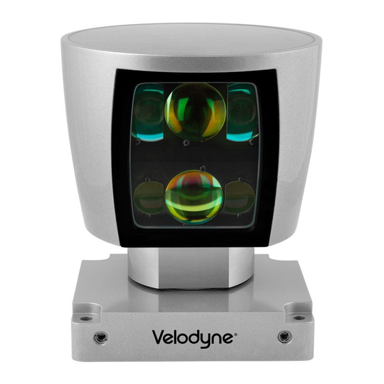
- Page 1 USER’S MANUAL AND PROGRAMMING GUIDE HDL-64E S3 High Definition LiDAR Sensor...
-
Page 2: Table Of Contents
2. Develop Your Own Application-Specific Point-Cloud Viewer ........... 9 Change Run-Time Parameters....................12 Sample Batch File (.bat)......................12 Sample SERCMD.txt file ......................12 Available Serial Commands HDL-64E S3 .................13 Control the Spin Rate........................14 Change Spin Rate in Flash Memory ..................14 Change Spin Rate in RAM Only.....................14 Limit Horizontal FOV Data Collected ..................14... - Page 3 HDL-64E S3 High Definition LiDAR Sensor Page 3 Appendix D: MATLAB Sample Code ..................29 Calibration and Sensor Parameter Data..................30 Appendix E: Data Packet Format ..................31 Data Packet Overview.......................31 Status Type Rotation.........................32 Status Value Example for Status Types of H, M, S, D, N, Y, G, T and V: .......32 GPS Status Values ........................33...
-
Page 4: Safety Notices
4. Follow Instructions — All operating and use instructions should be followed. 5. Servicing — The user should not attempt to service the product beyond what is described in the operating instructions. All other servicing should be referred to Velodyne. 63-HDL64ES3 REV K Velodyne LiDAR, Inc. -
Page 5: Introduction
NOTE: The HDL-64E S3 High Definition LiDAR sensor is referred to for brevity as “the sensor” throughout this manual. This manual and programming guide covers:... -
Page 6: Principles Of Operation
120 meters. The sensor employs a direct drive motor system with no belts or chains in the drive train. See the specifications at the end of this manual for more information about sensor operating conditions. Figure 1: HDL-64E S3 Design Overview 63-HDL64ES3 REV K Velodyne LiDAR, Inc. - Page 7 HDL-64E S3 High Definition LiDAR Sensor Page 7 360° Spinning Lidar Sensor 26.8° Valid Data Range 0.9 m to 120 m (3’ to 394’) Uncalibrated Point Cloud Data Packets Calibrated Point Cloud Data as 3D image Digital Sensor XML Laser...
-
Page 8: Installation
RPM. Ethernet M12 D-CODED connector is provided on the unit. Velodyne recommends using a category 6 cable (shielded, twisted pair) for the Ethernet cable. NOTE: The sensor is only compatible with network cards that have either MDI or AUTO MDIX capability. -
Page 9: View Image
The quickest way to view the data collected as a live image is to use the included Digital Sensor Recorder (DSR) application. DSR is Velodyne’s point-cloud processing data viewer software. DSR reads in the packets from the sensor over Ethernet, performs the necessary calculations to determine point locations and then plots the points in 3D on your PC monitor. - Page 10 HDL-64E S3 High Definition LiDAR Sensor Page 10 .xml Calibration Parameters Parameter Unit Description Values The rotational correction angle for Positive factors rotate to the rotCorrection degree each laser, as viewed from the back left. Negative values rotate to of the sensor.
- Page 11 3D space referred to by the return. Intensity and distance offsets must also be applied. Each sensor comes from Velodyne’s factory calibrated using a dual-point calibration methodology, explained further in Appendix F.
-
Page 12: Change Run-Time Parameters
HDL-64E S3 High Definition LiDAR Sensor Page 12 Change Run-Time Parameters The sensor has several run-time parameters that can be changed using the RS-232 serial port. For all commands, use the following serial parameters: Baud 9600 Parity: None Data bits: 8 Stop bits: 1 NOTE: All serial commands, except one version of the spin rate command, store data in the sensor’s... -
Page 13: Available Serial Commands Hdl-64E S3
HDL-64E S3 High Definition LiDAR Sensor Page 13 Available Serial Commands HDL-64E S3 More information about these commands is on the pages following the table below. Command Description Parameters Set spin rate from 0300 to 1200 RPM in flash •... -
Page 14: Control The Spin Rate
HDL-64E S3 High Definition LiDAR Sensor Page 14 Control the Spin Rate Change Spin Rate in Flash Memory The sensor can spin at rates ranging from 0300 RPM (5 Hz) to 1200 RPM (20 Hz). The default is 0600 RPM (10 Hz). Changing the spin rate does not change the data rate - the unit sends out the same number of packets (at a rate of 1.3 million data points per second) regardless of its spin rate. -
Page 15: Define Sensor Memory Ip Source And Destination Addresses
HDL-64E S3 High Definition LiDAR Sensor Page 15 The following diagram shows the HFOV from the top view of the sensor. Examples of HFOV Command Settings Case 1: FOV 0° to 360° FOV command: #HDLFOV000360$ Case 2: FOV 0° to 90°... - Page 16 HDL-64E S3 High Definition LiDAR Sensor Page 16 To activate dual returns and set the return priority, issue a serial command of the case sensitive format: #HDLRETS$ Strongest return only, this is the default setting. #HDLRETL$ Last return only. #HDLRETB$ Both strongest and last returns. If the strongest return is equal to the last return, the next strongest return is reported.
-
Page 17: Laser Output Power Level Management And Reporting
HDL-64E S3 High Definition LiDAR Sensor Page 17 Laser Output Power Level Management and Reporting Under poor visibility conditions, such as fog and dust, setting the laser output to full power can be beneficial. You can toggle the output power between AUTO (the default setting), or set a fixed value for all lasers from 0 and 7 (with 7 being full power). -
Page 18: Upload Calibration Data
HDL-64E S3 High Definition LiDAR Sensor Page 18 Upload Calibration Data Sensors used the .xml file exclusively for calibration data. The calibration data found in the .xml file can be uploaded and saved to the unit’s flash memory by following the steps outlined below. -
Page 19: Packet Format And Status Byte For Gps Time Stamping
HDL-64E S3 High Definition LiDAR Sensor Page 19 Packet Format and Status Byte for GPS Time Stamping The 6 bytes at the end of the data packet report GPS timing and synchronization data. For every packet, the last 6 bytes are formatted as follows:... -
Page 20: Laser Firing Sequence And Timing
HDL-64E S3 High Definition LiDAR Sensor Page 20 Laser Firing Sequence and Timing If the GPS timestamp feature is used, it can be useful to determine the exact firing time for each laser so as to properly time-align with the other data sources. -
Page 21: Firmware Updates
From time to time Velodyne issues firmware updates. To update the sensor’s firmware: NOTE: Because the sensor has no physical indication that a firmware update was successful, Velodyne recommends that you monitor the data packet during the update process. During the update process, the data packets will drop suddenly to zero. -
Page 22: Appendix A: Mechanical Drawings
HDL-64E S3 High Definition LiDAR Sensor Page 22 Appendix A: Mechanical Drawings Figure 4: Top View Figure 5: Rear Unit View Velodyne LiDAR, Inc. 2019 © 63-HDL64ES3 REV K... - Page 23 HDL-64E S3 High Definition LiDAR Sensor Page 23 Figure 6: Side and Front Unit View Figure 7: Bottom Unit View Velodyne LiDAR, Inc. 2019 © 63-HDL64ES3 REV K...
- Page 24 HDL-64E S3 High Definition LiDAR Sensor Page 24 Figure 8: Mounting Surface Example Velodyne LiDAR, Inc. 2019 © 63-HDL64ES3 REV K...
-
Page 25: Appendix B: Connector Pin Outs
HDL-64E S3 High Definition LiDAR Sensor Page 25 Appendix B: Connector Pin outs Power, Serial & GPS Connector Power, Serial & GPS Connector J1 Cable Mating Color Description Connector Supply voltage (+12 to +32 VDC Input) Black Ground Green PPS Input (Optional - from GPS) -
Page 26: Appendix C: Digital Sensor Recorder (Dsr)
HDL-64E S3 High Definition LiDAR Sensor Page 26 Appendix C: Digital Sensor Recorder (DSR) DSR is a 3D point-cloud visualization software program designed for use with the sensor. This software is an “out of the box” tool for the rendering and recording of point cloud data from the HDL unit. -
Page 27: Record Data
HDL-64E S3 High Definition LiDAR Sensor Page 27 Record Data 1. Confirm the input of streaming data through the live playback feature. 2. Click the Record button. RECORD button = 3. Enter the name and location for the pcap file to be created. -
Page 28: Dsr Key Controls
HDL-64E S3 High Definition LiDAR Sensor Page 28 DSR Key Controls You can use the following keyboard shortcuts and mouse controls with the DSR Viewer. Keyboard Shortcuts X Shift: Zoom: L = Left Z = Zoom in H = Right... -
Page 29: Appendix D: Matlab Sample Code
HDL-64E S3 High Definition LiDAR Sensor Page 29 Appendix D: MATLAB Sample Code Matlab sample code to read calibration data from sensor output. fileFilter = ‘*.pcap‘; [File^name,Directory]=uigetfile(fileFilter,‘Open a .pcap file‘) ; Filename=[Directory File^name]; tic; fid=fopen(Filename); ttc=fread(fid,40); ttc=fread(fid,42); ttc=fread(fid,inf,‘1206*uint8=>uint8‘,58); %ttch=dec2hex(ttc); % Determine how many data packets. -
Page 30: Calibration And Sensor Parameter Data
HDL-64E S3 High Definition LiDAR Sensor Page 30 FocalDist(i)=FocalDist(i)—65536; end FocalDist(i)=FocalDist(i)/10; FocalSlope(i)=temp2(5)*256+temp2(4); if FocalSlope(i)>32768 FocalSlope(i)=FocalSlope(i)—65536; end FocalSlope(i)=FocalSlope(i)/10; % Maximum and Minimum Intensity only 1 Byte each. MinIntensity(i)=temp2(6); MaxIntensity(i)=temp2(7); End % Done with correction factors. % Get Unit Parameter Data s=Ind(1) char(status(s—80:s+6)) value(s—80:s+6) Version=dec2hex(value(s—1)) Temperature=value(s—2) GPS=value(s—3) -
Page 31: Appendix E: Data Packet Format
HDL-64E S3 High Definition LiDAR Sensor Page 31 Appendix E: Data Packet Format The sensor outputs UDP Ethernet packets. Each packet contains a header, a data payload of firing data and status data. Data packets are assembled with the collection of all firing data for six upper block sequences and six lower block sequences. -
Page 32: Status Type Rotation
HDL-64E S3 High Definition LiDAR Sensor Page 32 Status Type Rotation Status Type Rotates Through ASCII String Description Hours Minutes Seconds Date Month Year Temperature °C Firmware Version Status Type Calibration & Unit Parameters (refer to table later in this... -
Page 33: Gps Status Values
HDL-64E S3 High Definition LiDAR Sensor Page 33 GPS Status Values GPS Status Values ASCII String and Definition A= GPS receiving both sync signal and NMEA time command record V = GPS receiving NMEA time command record only P = GPS receiving sync signal only... - Page 34 HDL-64E S3 High Definition LiDAR Sensor Page 34 Status Value Types Cycle # String Parameter ASCII Value Interpretation Hours Minutes Seconds Date Month Year GPS Status Temperature Firmware Version “U” 85 = 0x55= U “N” 76 = 0x4E = N “I”...
- Page 35 HDL-64E S3 High Definition LiDAR Sensor Page 35 Status Value Types Cycle # String Parameter ASCII Value Interpretation Warning Warning Bits Reserved Reserved Reserved Reserved Reserved Reserved Integer Laser 1 Vertical Correction Low Byte ÷ 2 Byte Signed Integer 100 to Scale...
- Page 36 HDL-64E S3 High Definition LiDAR Sensor Page 36 Status Value Types Cycle # String Parameter ASCII Value Interpretation Integer Laser 63 Vertical Correction Low Byte ÷ 2 Byte Signed Integer 100 to Scale Vertical Correction High Byte Rotational Correction Low Byte ÷...
- Page 37 HDL-64E S3 High Definition LiDAR Sensor Page 37 Motor Speed Low Byte 2 Byte Signed Integer (RPM) Motor Speed High Byte FOV Start Angle Low Byte ÷ 2 Byte Integer 100 to Scale FOV Start Angle High Byte FOVE End Angle Low Byte ÷...
-
Page 38: Warning Status Bits
HDL-64E S3 High Definition LiDAR Sensor Page 38 Total Bytes for All Laser Calibration & Parameter Data 1820 = 1792 + 28 = (4 x 7 s 64) + (4 x7) Only one set of the Parameter Data Is Required... -
Page 39: Crc Checksum Algorithm
HDL-64E S3 High Definition LiDAR Sensor Page 39 CRC Checksum Algorithm The following is an example of the CRC checksum algorithm for calibration data. #include <stdio.h> #define POLYNOMIAL 0x8005 //Standard CRC-16 polynomial // CRC = A542 unsigned char TestDATA[]= 0xfe,0x7b,0xfd,0x27,0x05,0x0e,0x05,0x53,0x05,0x36,0x00,0xC5,0x00,0x19,0x36,0xb0,0x00,0x0a... - Page 40 HDL-64E S3 High Definition LiDAR Sensor Page 40 Velodyne LiDAR, Inc. 2019 © 63-HDL64ES3 REV K...
- Page 41 HDL-64E S3 High Definition LiDAR Sensor Page 41 Velodyne LiDAR, Inc. 2019 © 63-HDL64ES3 REV K...
- Page 42 HDL-64E S3 High Definition LiDAR Sensor Page 42 Velodyne LiDAR, Inc. 2019 © 63-HDL64ES3 REV K...
-
Page 43: Appendix F: Dual Two Point Calibration Methodology & Code Samples
Appendix F: Dual Two Point Calibration Methodology & Code Samples Velodyne uses a dual point calibration methodology to calculate the values in the .xml file. This section describes this calibration methodology. The steps for the calibration are as follows: 1. Perform far point calibration at 25.04m 2. - Page 44 HDL-64E S3 High Definition LiDAR Sensor Page 44 float xyDistance = distance * cosVertAngle;// — vOffsetCorr * sinVertAngle; float xx = xyDistance * sinRotAngle;// — hOffsetCorr * cosRotAngle + pos.getX(); float yy = xyDistance * cosRotAngle;// + hOffsetCorr * sinRotAngle + pos.getY();...
-
Page 45: Intensity Compensation Vs Distance
HDL-64E S3 High Definition LiDAR Sensor Page 45 Intensity Compensation vs Distance Intensity compensation is done in the software for different channels by changing a parameter in the calibration window until the measurement Here K is slope getting from cal data. Intensity gets to max at focaldistance for different channel and it’s from cal data too. -
Page 46: Intensity Value Corrected By Distance
HDL-64E S3 High Definition LiDAR Sensor Page 46 Intensity Value Corrected by Distance for (guint i=0; i< VLS_LASER_PER_FIRING; i++) { guit laser = i + base; if (!db->getEnabled(laser)) continue; bool intensity =db->getIntensity(laser); if (!intensity: { glColor3fv(db->getDisplayColor(laser).rgb); } else { guchar minIntensity = 0, maxIntensity = 0;... -
Page 47: Appendix G: Ethernet Timing Tables
HDL-64E S3 High Definition LiDAR Sensor Page 47 Appendix G: Ethernet Timing Tables The sensor Ethernet timing tables show how much time elapses between the actual capturing of a point’s data event and when that point is an event output from the sensor. By registering the event of the Ethernet data capture, you can calculate back in time the exact time at which any particular distance point was captured. - Page 48 HDL-64E S3 High Definition LiDAR Sensor Page 48 Laser Firing Time Table for HDL64 S3 Firmware F2 Dual Return Laser Number 0—15 and 32—47 (Upper, Lower) Data Laser Block Block 0, 32 1, 33 2, 34 3, 35 4, 36...
-
Page 49: Laser And Detector Arrangement
HDL-64E S3 High Definition LiDAR Sensor Page 49 Laser and Detector Arrangement The images below show the arrangement of the lasers and detectors in the unit. Lasers as Seen from the Back of the Unit Laser as Seen on the Wall 63-HDL64ES3 REV K Velodyne LiDAR, Inc. -
Page 50: Appendix I: Angular Resolution
HDL-64E S3 High Definition LiDAR Sensor Page 50 Appendix I: Angular Resolution Total Laser Points per Points Per Angular Revolution Laser per Resolution (Hz) Revolution (degrees) 0300 266,627 4167 0.0864 0600 133,333 2083 0.1728 0900 88,889 1389 0.2592 1200 66,657 1042 0.3456... -
Page 51: Appendix J: Troubleshoot
HDL-64E S3 High Definition LiDAR Sensor Page 51 Appendix J: Troubleshoot Use the chart below to troubleshoot common problems with the sensor. Problem Resolution Unit doesn’t spin Verify power connection and polarity. Verify proper voltage — should be 24 volts drawing about 3.5 to 4 amps. -
Page 52: Appendix K: Service And Maintenance
Appendix K: Service and Maintenance No service or maintenance requirements or procedures exist for the sensors. However, Velodyne does offer a preventative maintenance service for a fee. For service maintenance, please contact Velodyne at (408) 465-2800, or log on to our website at www.velodynelidar.com. -
Page 53: Appendix L: Specifications
High Definition LiDAR Sensor Page 53 Appendix L: Specifications Sensor specifications (including environmental and regulatory Specifications) have been moved to product data sheets section of the Velodyne LiDAR website at this address: www.velodynelidar.com For additional information, contact Velodyne LiDAR Sales at www.velododynelidar.com/contacts.php 63-HDL64ES3 REV K Velodyne LiDAR, Inc. - Page 54 Service E mail: lidarservice@velodyne.com Product E mail: help@velodyne.com Technical E mail: lidarhelp@velodyne.com Sales E mail: lidar@velodyne.com All Velodyne products are made in the U.S.A. Specifications subject to change without notice. Other trademarks or registered trademarks are property of their respective owner. 63-HDL64ES3...
Need help?
Do you have a question about the HDL-64E S3 and is the answer not in the manual?
Questions and answers