Sign In
Upload
Manuals
Brands
Velodyne Manuals
Accessories
VLP-32C
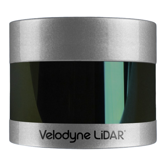
Velodyne VLP-32C 360-degree Lidar Sensor Manuals
Manuals and User Guides for Velodyne VLP-32C 360-degree Lidar Sensor. We have
2
Velodyne VLP-32C 360-degree Lidar Sensor manuals available for free PDF download: User Manual
Velodyne VLP-32C User Manual (138 pages)
Brand:
Velodyne
| Category:
Accessories
| Size: 20 MB
Table of Contents
Limited Warranty
2
Revision History
3
Table of Contents
4
Chapter 1 • about this Manual
16
Manual Scope
16
Prerequisite Knowledge
16
Audience
16
Document Conventions
16
Table 1-1 Document Conventions
16
Figure 2-1 Example 3D Sensing System
18
Overview
18
Chapter 2 • VLP-16 Overview
19
Product Models
19
Time of Flight
19
Data Interpretation Requirements
19
Table 2-1 3D Sensing System Components
19
Chapter 3 • Safety Precautions
20
Warning and Caution Definitions
20
Caution Hazard Alerts
20
Safety Overview
20
Electrical Safety
20
Mechanical Safety
20
Laser Safety
21
Figure 3-1 Class 1 Laser
21
Chapter 4 • Unboxing & Verification
22
What's in the Box
22
Variants
22
Verification Procedure
22
Network Setup in Isolation
23
Access Sensor's Web Interface
24
Figure 4-1 Sensor Network Settings
24
Figure 4-2 Interface Box (Power and Data Connections)
25
Visualize Live Sensor Data with Veloview
26
Figure 4-3 Sample Web Interface Main Configuration Screen
26
Figure 4-4 Veloview Open Sensor Stream
27
Figure 4-5 Veloview Select Sensor Calibration
27
Veloview Operation
27
Figure 4-6 Veloview Sensor Stream Display
28
Chapter 5 • Installation & Integration
29
Overview
29
Mounting
29
Encapsulation, Solar Hats, and Ventilation
30
Connections
30
Figure 5-1 Mounting Details
30
Integrated Cable and Interface Box
31
Operation Without an Interface Box
31
Power
31
Chapter 6 • Key Features
32
Calibrated Reflectivity
32
Laser Return Modes
32
Single Return Modes: Strongest, Last
32
Multiple Returns
33
Dual Return Mode
33
Figure 6-1 a Single Return
33
Figure 6-2 Dual Return with Last and Strongest Returns
34
Figure 6-3 Dual Return with Second Strongest Return
35
Figure 6-4 Dual Return with Far Retro-Reflector
36
Phase Locking Multiple Sensors
37
Figure 6-5 Forestry Application Multiple Returns
37
Figure 6-6 Phase Locking Example
38
Chapter 7 • Sensor Inputs
39
Power Requirements
39
Interface Box Signals
40
Table 7-1 Interface Box Signals
40
Figure 7-1 Interface Box (Sensor Power and Data Connections)
40
Ethernet Interface
41
GPS, Pulse Per Second (PPS) and NMEA GPRMC Message
41
GPS Input Signals
41
Electrical Requirements
41
Timing and Polarity Requirements
41
Figure 7-2 Synchronizing PPS with NMEA GPRMC Message
42
Figure 7-3 PPS Signal Closely Followed by NMEA GPRMC Message
42
Figure 7-4 PPS Signal Followed 600 Ms Later by NMEA GPRMC Message
43
GPS Connection Scenarios
44
Connecting a Garmin 18X LVC GPS Receiver
44
Connecting to a Computer's Serial Port
44
Figure 7-5 RS-232 Example Transmission
44
Figure 7-6 Garmin GPRMC Message
44
Connecting to a Microcomputer's UART
45
Figure 7-7 DB9 Pin-Outs (DTE) and USB-To-Serial Adapter
45
NMEA Message Formats
46
Figure 7-8 Signal Directly from UART (Incorrect Polarity)
46
Figure 7-9 Inverted Signal from UART (Correct Polarity)
46
Pre-NMEA Version 2.3 Message Format
46
NMEA Version 2.3 Message Format
47
Table 7-2 Pre-NMEA Version 2.3 Message Format
47
Table 7-3 Post-NMEA Version 2.3 Message Format
47
Accepting NMEA Messages Via Ethernet
48
Chapter 8 • Sensor Operation
49
Firing Sequence
49
Throughput Calculations
49
Data Packet Rate
49
Figure 8-1 Firing Sequence Timing
49
Position Packet Rate
50
Total Packet Rate
50
Laser Measurements Per Second
50
Dual Return Mode
50
Single Return Mode (Strongest, Last)
50
Rotation Speed (RPM)
50
Horizontal Angular (Azimuth) Resolution
50
Rotation Speed Fluctuation and Point Density
51
Table 8-1 Rotation Speed Vs Resolution
51
Figure 8-2 Point Density Example
51
Chapter 9 • Sensor Data
52
Sensor Origin and Frame of Reference
52
Calculating X,Y,Z Coordinates from Collected Spherical Data
52
Table 9-1 Vertical Angles (Ω) by Laser ID and Model
53
Figure 9-1 VLP-16 Sensor Coordinate System
53
Packet Types and Definitions
54
Definitions
54
Azimuth
55
Data Block
55
Data Point
55
Firing Sequence
55
Laser Channel
55
Time Stamp
55
Factory Bytes
56
Data Packet Structure
56
Table 9-2 Factory Byte Values
56
Figure 9-2 VLP-16 Single Return Mode Data Structure
57
Figure 9-3 VLP-16 Dual Return Mode Data Structure
58
Figure 9-4 Single Return Mode Packet Data Trace (Packet Start)
59
Figure 9-5 Single Return Mode Packet Data Trace (Ending)
59
Position Packet Structure
60
Table 9-3 Position Packet Structure Field Offsets
60
Table 9-4 PPS Status Byte Values
60
Discreet Point Timing Calculation
61
Figure 9-6 Wireshark Position Packet Trace
61
Figure 9-7 Firing Sequence Timing
62
Figure 9-8 Example Data Point Timing Calculation
63
Figure 9-9 Single Return Mode Timing Offsets (in Μs)
64
Precision Azimuth Calculation
65
Figure 9-10 Dual Return Mode Timing Offsets (in Μs)
65
Converting PCAP Files to Point Cloud Formats
66
Chapter 10 • Sensor Communication
68
Web Interface
68
Configuration Screen
69
Figure 10-1 VLP-16 Configuration Screen
69
Table 10-1 Configuration Screen Functionality and Features
69
Correctly Reset MAC Address to Factory MAC Address
71
MAC Address
71
System Screen
72
Table 10-2 System Screen Functionality and Features
72
Figure 10-2 VLP-16 System Screen
72
Info Screen
73
Table 10-3 Info Screen Functionality and Features
73
Figure 10-3 VLP-16 Info Screen
73
Diagnostics Screen
75
Table 10-4 System Screen Functionality and Features
75
Figure 10-4 VLP-16 Diagnostics Screen
75
Sensor Control with Curl
76
Using Curl with Velodyne Lidar Sensors
76
Curl Command Parameters
76
Command Line Curl Examples
77
Get Diagnostic Data
77
Conversion Formulas
78
Interpret Diagnostic Data
78
Top:hv
78
Top:lm20_Temp
79
Bot:i_Out
80
Bot:lm20_Temp
80
Bot:pwr_1_2V
80
Top:pwr_Vccint
80
Bot:pwr_1_25V
81
Get Sensor Status
82
Get Snapshot
82
Set Motor RPM
82
Network Configuration
83
Reset System
83
Save Configuration
83
Set Field of View
83
Set Host (Destination) IP Address
83
Set Return Type (Strongest, Last, Dual)
83
Set Data Port
84
Set DHCP
84
Set Gateway
84
Set Netmask
84
Set Network (Sensor) IP Address
84
Set Telemetry Port
84
Curl Example Using Python
84
Chapter 11 • Troubleshooting
87
Troubleshooting Process
87
Table 11-1 Common Problems and Resolutions
87
Turned DHCP On, Lost Contact with Sensor
88
Service and Maintenance
89
Fuse Replacement
89
Technical Support
90
Purchased through a Distributor
90
Factory Support
90
Support Desk
90
Return Merchandise Authorization (RMA)
90
Appendix A • Sensor Specifications
91
Appendix B • Firmware Update
92
Firmware Update Procedure
92
Figure B-1 Velodyne Downloads Page
92
Figure B-2 Compare Firmware Versions
93
Figure B-3 Select New Firmware Image
94
Figure B-4 Upload New Firmware Image
95
Figure B-5 Firmware Update Complete Page
96
Figure B-6 Finalize Firmware Update
97
Figure B-7 Verify Firmware Versions
98
Special Procedure to Update Firmware
98
If an Error Occurs
99
Appendix C • Mechanical Diagrams
100
Interface Box Mechanical Drawing
101
Figure C-1 Interface Box Mechanical Drawing 50-6001 Rev a
101
And Puck LITE Mechanical Drawing
102
Figure C-2 VLP-16 and Puck LITE Mechanical Drawing 86-0101 Rev B1
102
And Puck LITE Optical Drawing
103
Figure C-3 VLP-16 and Puck LITE Optical Drawing 86-0101 Rev B1
103
And Puck LITE Optical Keep out Zone
104
Figure C-4 VLP-16 and Puck LITE Optical Keep out Zone 86-0101 Rev B1
104
Puck Hi-Res Mechanical Drawing
105
Figure C-5 Puck Hi-Res Mechanical Drawing 86-0129 Rev a
105
Puck Hi-Res Optical Drawing
106
Figure C-6 Puck Hi-Res Optical Drawing 86-0129 Rev a
106
Puck Hi-Res Optical Keep out Zone
107
Figure C-7 Puck Hi-Res Optical Keep out Zone 86-0129 Rev a
107
Appendix D • Wiring Diagrams
108
Interface Box Wiring Diagram
109
Figure D-1 Interface Box Wiring Diagram 86-0107A
109
Interface Box Schematic
110
Figure D-2 Interface Box Schematic 69-8230A
110
Appendix E • Veloview
111
Features
111
Install Veloview
112
Visualize Streaming Sensor Data
112
Figure E-1 Veloview Open Sensor Stream
112
Figure E-2 Veloview Select Sensor Calibration
113
Figure E-3 Veloview Sensor Stream Display
113
Capture Streaming Sensor Data to PCAP File
114
Replay Captured Sensor Data from PCAP File
114
Figure E-4 Veloview Record Button
114
Figure E-5 Veloview Open Capture File
115
Figure E-6 Veloview Play Button
115
Figure E-7 Veloview Spreadsheet Tool
116
Figure E-8 Veloview Data Point Table
116
Figure E-9 Veloview Show Only Selected Elements
117
Figure E-10 Veloview Select All Points
117
Figure E-11 Veloview List Selected Points
118
Appendix F • Laser Pulse
119
The Semiconductor Laser Diode
119
Figure F-1 Laser Diode Concept
119
Laser Patterns
120
Laser Spot Pattern
120
Laser Scan Pattern
120
Figure F-2 Laser Spot Shape
120
Beam Divergence
121
Figure F-3 Laser Spots on a Wall
121
Table F-1 VLP-16 Beam Divergence
122
Table F-2 Dimensions of VLP-16 Laser Spots at Distance
122
Appendix G • Time Synchronization
123
Introduction
123
Background
123
Figure G-1 Web Interface PPS and GPS Qualifier Option Selections
123
PPS Qualifier
124
Require GPS Receiver Valid
124
Require PPS Lock
124
Figure G-2 Top of Hour Counters
124
Delay
125
GPS Qualifier
125
Application
125
Logic Tables
125
Figure G-3 Sub-Second Counter Behavior
125
Figure G-4 Minutes and Seconds Counter Behavior
126
Appendix H • Phase Lock
127
Phase Lock
127
Setting the Phase Lock
127
Figure H-1 Direction of Laser Firing
127
Application Scenarios
128
Figure H-2 Configuration Screen - Phase Lock
128
Figure H-3 Right and Left Sensor Phase Offset
129
Figure H-4 Fore and Aft Sensor Phase Offset
129
Field of View
130
Figure H-5 Sensor Data Shadows
130
Appendix I • Sensor Care
131
Cleaning the Sensor
131
Required Materials
131
Determine Method of Cleaning
132
Method One
132
Method Two
132
Method Three
132
Method Four
133
Appendix J • Network Configuration
134
Ethernet and Network Setup
134
Defaults
134
Establishing Communication Via Ethernet
134
Network Considerations
135
Throughput Requirements
135
Figure J-1 Sensor Network Settings
135
Single Sensor Transmitting to a Broadcast Address
136
Multiple Sensors in the same Network
136
Figure J-2 Single Sensor Broadcasting on a Simple Network
136
Multiple Sensors Transmitting to a Broadcast Address
136
Figure J-3 Multiple Sensors - Improper Network Setup
137
Figure J-4 Multiple Sensors - Proper Network Setup
137
Multiple Sensors Transmitting to a Specific Address
137
Advertisement
Velodyne VLP-32C User Manual (136 pages)
Brand:
Velodyne
| Category:
Accessories
| Size: 14 MB
Table of Contents
Method
2
Method
3
Table of Contents
4
Chapter 1 • about this Manual
16
Manual Scope
16
Prerequisite Knowledge
16
Audience
16
Document Conventions
16
Table 1-1 Document Conventions
16
Figure 2-1 Example 3D Sensing System
18
Chapter 2 • VLP-32C Overview 2.1 Overview
19
Product Models
19
Time of Flight
19
Data Interpretation Requirements
19
Table 2-1 3D Sensing System Components
19
Chapter 3 • Safety Precautions
20
Warning and Caution Definitions
20
Caution Hazard Alerts
20
Safety Overview
20
Electrical Safety
20
Mechanical Safety
20
Laser Safety
20
Figure 3-1 Class 1 Laser
21
Chapter 4 • Unboxing & Verification
22
What's in the Box
22
Variants
22
Verification Procedure
22
Network Setup in Isolation
23
Figure 4-1 Sensor Network Settings
23
Access Sensor's Web Interface
24
Figure 4-2 Interface Box (Power and Data Connections)
24
Figure 4-3 Sample Web Interface Main Configuration Screen
25
Visualize Live Sensor Data with Veloview
26
Veloview Operation
27
Figure 4-4 Veloview Open Sensor Stream
27
Figure 4-5 Veloview Select Sensor Calibration
27
Figure 4-6 Veloview Sensor Stream Display
28
Chapter 5 • Installation & Integration
29
Overview
29
Mounting
29
Figure 5-1 Mounting Details
29
Encapsulation, Solar Hats, and Ventilation
30
Connections
30
Interface Box and Cable
31
Operation Without an Interface Box
31
Power
31
Chapter 6 • Key Features
32
Calibrated Reflectivity
32
Laser Return Modes
32
Single Return Modes: Strongest, Last
32
Multiple Returns
33
Dual Return Mode
33
Figure 6-1 a Single Return
33
Figure 6-2 Dual Return with Last and Strongest Returns
34
Figure 6-3 Dual Return with Second Strongest Return
35
Figure 6-4 Dual Return with Far Retro-Reflector
36
Phase Locking Multiple Sensors
37
Figure 6-5 Forestry Application Multiple Returns
37
Figure 6-6 Phase Locking Example
38
Chapter 7 • Sensor Inputs
39
Power Requirements
39
Interface Box Signals
40
Table 7-1 Interface Box Signals
40
Figure 7-1 Interface Box
40
Ethernet Interface
41
GPS, Pulse Per Second (PPS) and NMEA Sentence
41
GPS Input Signals
41
Electrical Requirements
41
Timing and Polarity Requirements
41
Figure 7-2 Synchronizing PPS with NMEA GPRMC Message
41
Figure 7-3 PPS Signal Closely Followed by NMEA GPRMC Message
42
Figure 7-4 PPS Signal Followed 600 Ms Later by NMEA GPRMC Message
42
Figure 7-5 RS-232 Example Transmission
43
GPS Connection Scenarios
44
Connecting a Garmin 18X LVC GPS Receiver
44
Figure 7-6 Garmin 18X LVC Configuration
44
Figure 7-7 Garmin GPRMC Message
45
Connecting to a Computer's Serial Port
46
Connecting to a Microcomputer's UART
46
Figure 7-8 DB9 Pin-Outs (DTE) and USB-To-Serial Adapter
46
Figure 7-9 Signal Directly from UART (Incorrect Polarity)
46
NMEA Message Formats
47
Pre-NMEA Version 2.3 Message Format
47
Figure 7-10 Inverted Signal from UART (Correct Polarity)
47
NMEA Version 2.3 Message Format
48
Table 7-2 Pre-NMEA Version 2.3 Message Format
48
Table 7-3 Post-NMEA Version 2.3 Message Format
48
Accepting NMEA Messages Via Ethernet
49
Chapter 8 • Sensor Operation
50
Firing Sequence
50
Throughput Calculations
50
Data Packet Rate
50
Figure 8-1 Firing Sequence Timing
50
Position Packet Rate
51
Total Packet Rate
51
Laser Measurements Per Second
51
Single Return Mode (Strongest, Last)
51
Dual Return Mode
51
Rotation Speed (RPM)
51
Horizontal Angular (Azimuth) Resolution
51
Rotation Speed Fluctuation and Point Density
52
Table 8-1 Rotation Speed Vs Resolution
52
Figure 8-2 Point Density Example
52
Chapter 9 • Sensor Data
53
Sensor Origin and Frame of Reference
53
Calculating X,Y,Z Coordinates from Collected Spherical Data
53
Packet Types and Definitions
54
Definitions
54
Figure 9-1 VLP-32C Sensor Coordinate System
54
Firing Sequence
55
Laser Channel
55
Data Point
55
Azimuth
55
Data Block
55
Time Stamp
55
Factory Bytes
56
Data Packet Structure
56
Table 9-1 Factory Byte Values
56
Figure 9-2 VLP-32 Single Return Mode Data Structure
57
Table 9-2 VLP-32C Data Order in Data Block
58
Figure 9-3 VLP-32 Dual Return Mode Data Structure
58
Position Packet Structure
59
Table 9-3 Position Packet Structure Field Offsets
59
Table 9-4 PPS Status Byte Values
61
Figure 9-4 Wireshark Position Packet Trace
61
Discreet Point Timing Calculation
62
Table 9-5 VLP-32C's Lasers Fire in Pairs
62
Figure 9-5 Firing Sequence Timing
62
Figure 9-6 Example Data Point Timing Calculation
64
Figure 9-7 Single Return Mode Timing Offsets (in Μs)
65
Precision Azimuth Calculation
66
Table 9-6 VLP-32C Azimuth Offsets by Elevation
66
Figure 9-8 Dual Return Mode Timing Offsets (in Μs)
66
Converting PCAP Files to Point Cloud Formats
69
Chapter 10 • Sensor Communication
70
Web Interface
70
Configuration Screen
71
Table 10-1 Configuration Screen Functionality and Features
71
Figure 10-1 VLP-32C Configuration Screen
71
MAC Address
73
Correctly Reset MAC Address to Factory MAC Address
73
System Screen
74
Table 10-2 System Screen Functionality and Features
74
Figure 10-2 VLP-32C System Screen
74
Info Screen
75
Table 10-3 Info Screen Functionality and Features
75
Figure 10-3 VLP-32C Info Screen
75
Diagnostics Screen
77
Table 10-4 System Screen Functionality and Features
77
Figure 10-4 VLP-32C Diagnostics Screen
77
Sensor Control with Curl
78
Using Curl with Velodyne Lidar Sensors
78
Curl Command Parameters
78
Command Line Curl Examples
79
Get Diagnostic Data
79
Conversion Formulas
80
Interpret Diagnostic Data
80
Top:hv
80
Top:lm20_Temp
81
Top:pwr_5V
81
Top:pwr_2_5V
81
Top:pwr_3_3V
81
Top:pwr_Raw
82
Top:pwr_Vccint
82
Bot:i_Out
82
Bot:lm20_Temp
82
Bot:pwr_V_In
84
Get Snapshot
84
Get Sensor Status
84
Set Motor RPM
84
Set Field of View
85
Set Return Type (Strongest, Last, Dual)
85
Save Configuration
85
Reset System
85
Network Configuration
86
Set Host (Destination) IP Address
86
Set Data Port
86
Set Telemetry Port
86
Set Network (Sensor) IP Address
86
Set Netmask
86
Set Gateway
86
Set DHCP
86
Curl Example Using Python
87
Chapter 11 • Troubleshooting
89
Troubleshooting Process
89
Table 11-1 Common Problems and Resolutions
89
Turned DHCP On, Lost Contact with Sensor
90
Service and Maintenance
91
Fuse Replacement
91
Technical Support
92
Purchased through a Distributor
92
Factory Support
92
Support Desk
92
Return Merchandise Authorization (RMA)
92
Appendix A • Sensor Specifications
93
Appendix B • Firmware Update
94
Firmware Update Procedure
94
Figure B-1 Velodyne Downloads Page
94
Figure B-2 Compare Firmware Versions
95
Figure B-3 Select New Firmware Image
96
Figure B-4 Upload New Firmware Image
97
Figure B-5 Firmware Update Complete Page
98
Figure B-6 Finalize Firmware Update
99
Special Procedure to Update Firmware
100
Figure B-7 Verify Firmware Versions
100
If an Error Occurs
101
Appendix C • Mechanical Diagrams
102
Interface Box Mechanical Drawing
103
Figure C-1 Interface Box Mechanical Drawing 50-6001 Rev a
103
VLP-32C Mechanical Drawing
104
Figure C-2 VLP-32C Mechanical Drawing 86-0130 Rev 1
104
Appendix D • Wiring Diagrams
105
Interface Box Wiring Diagram
106
Figure D-1 Interface Box Wiring Diagram 86-0107A
106
Interface Box Schematic
107
Figure D-2 Interface Box Schematic 69-8230A
107
Appendix E • Veloview
108
Features
108
Install Veloview
109
Visualize Streaming Sensor Data
109
Figure E-1 Veloview Open Sensor Stream
109
Figure E-2 Veloview Select Sensor Calibration
110
Capture Streaming Sensor Data to PCAP File
111
Figure E-3 Veloview Sensor Stream Display
111
Replay Captured Sensor Data from PCAP File
112
Figure E-4 Veloview Record Button
112
Figure E-5 Veloview Open Capture File
113
Figure E-6 Veloview Play Button
113
Figure E-7 Veloview Spreadsheet Tool
114
Figure E-8 Veloview Data Point Table
114
Figure E-9 Veloview Show Only Selected Elements
115
Figure E-10 Veloview Select All Points
115
Figure E-11 Veloview List Selected Points
116
Appendix F • Laser Pulse
117
The Semiconductor Laser Diode
117
Figure F-1 Laser Diode Concept
117
Laser Patterns
118
Laser Spot Pattern
118
Laser Scan Pattern
118
Figure F-2 Laser Spot Shape
118
Beam Divergence
119
Figure F-3 Laser Spots on a Wall
119
Table F-1 VLP-32C Beam Divergence
120
Appendix G • Time Synchronization
121
Introduction
121
Background
121
Figure G-1 Web Interface PPS and GPS Qualifier Option Selections
121
PPS Qualifier
122
Require GPS Receiver Valid
122
Require PPS Lock
122
Figure G-2 Top of Hour Counters
122
Delay
123
GPS Qualifier
123
Application
123
Logic Tables
123
Figure G-3 Sub-Second Counter Behavior
123
Figure G-4 Minutes and Seconds Counter Behavior
124
Appendix H • Phase Lock
125
Phase Lock
125
Setting the Phase Lock
125
Figure H-1 Direction of Laser Firing
125
Application Scenarios
126
Figure H-2 Configuration Screen - Phase Lock
126
Figure H-3 Right and Left Sensor Phase Offset
127
Figure H-4 Fore and Aft Sensor Phase Offset
127
Field of View
128
Figure H-5 Sensor Data Shadows
128
Appendix I • Sensor Care
129
Cleaning the Sensor
129
Required Materials
129
Determine Method of Cleaning the Ring Lens
129
Cleaning Tips
130
Method
130
Cleaning Non-Optical Sensor Surfaces
131
Appendix J • Network Configuration
132
Ethernet and Network Setup
132
Defaults
132
Establishing Communication Via Ethernet
132
Network Considerations
133
Throughput Requirements
133
Figure J-1 Sensor Network Settings
133
Single Sensor Transmitting to a Broadcast Address
134
Multiple Sensors in the same Network
134
Multiple Sensors Transmitting to a Broadcast Address
134
Figure J-2 Single Sensor Broadcasting on a Simple Network
134
Multiple Sensors Transmitting to a Specific Address
135
Figure J-3 Multiple Sensors - Improper Network Setup
135
Figure J-4 Multiple Sensors - Proper Network Setup
135
Advertisement
Related Products
Velodyne VLP-16
Velodyne VLS-128
Velodyne vLeve
Velodyne VMS-8
Velodyne VDR-10BV
Velodyne VA-1250X
Velodyne VRP-1200
Velodyne VDR-12 - REV A
Velodyne vQuiet
Velodyne VDR-12BV
Velodyne Categories
Subwoofer
Headphone
Accessories
Speakers
Amplifier
More Velodyne Manuals
Login
Sign In
OR
Sign in with Facebook
Sign in with Google
Upload manual
Upload from disk
Upload from URL