
Subscribe to Our Youtube Channel
Related Manuals for Stanley 0063AU5289


Summary of Contents for Stanley 0063AU5289
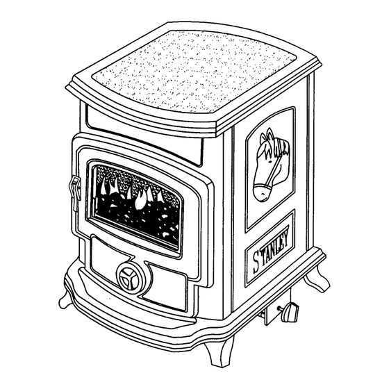
- Page 1 Shire Balanced Flue Gas Stove REMOTE CONTROL INSTALLATION AND OPERATION INSTRUCTIONS To ensure safety, satisfaction and reliable service this stove should be installed by a suitably qualified and competent person.
-
Page 2: Table Of Contents
TABLE OF CONTENTS PAGE Technical Data............3 General . -
Page 3: Technical Data
Appliance Category: may result in property damage or injury. Country of Designation: I.E., G.B., F.R., P.T.,I.T. Thank you for buying a Stanley Shire Balanced Flue E.S., N.L.,& B.E. Gas Stove. This room heater and special flue sys- Gas Type tem should be inspected before use and at least N.G.:... -
Page 4: Pre-Installation Assembly
MINIMUM CLEARANCES TO COMBUSTIBLE BS 5440: Parts 1 & 2, Installation of flues and MATERIALS (see figs 3- 6 Inclusive) ventilation for gas appliances of rated input not exceeding 60kw (1st, 2nd & 3rd family Back wall 6” (150mm) gases) Left side wall looking from front 5”... -
Page 5: Connection Of Wall Mounted Control Unit & Electrical Supply
HEARTH FITTING Fig.6 This stove MUST be installed on a concrete con- When installing the stove against a non- combustible wall leave a 2” space between structional hearth, or on a fire proof/non-combustible the back of the stove and the wall for air circulation (see fig. -
Page 6: Flue Connection
The telescopic section of the flue can vary in length FLUE CONNECTION from 400mm (16”) to 600mm (24”). When installing the stove do not use a flue length greater than The Shire Balanced Flue Stove is approved to be 600mm (24”) . The maximum allowable distance vented to the outdoors through an adjacent exterior between the stove and its flue terminal is 600mm wall. -
Page 7: Timber Framed Dwellings
TABLE 1 DIMENSION TERMINAL POSITION MINIMUM DISTANCE (MM) Directly below an opening window or other opening e.g. air brick Below gutters, soil pipes or drain pipes Below eaves Below balconies or car port roofs From vertical drain pipes and soil pipes From internal or external corners Above ground, roof or balcony level From a surface facing a terminal... -
Page 8: Gas Soundness Testing
CAUTION: Fig.11 The appliance must be isolated from gas supply system during any gas soundness testing at pres- sures in excess of 50 mbar. After testing gas supply pipe work, open isolation valve to stove and carry out gas soundness testing at normal working pressure 20 mbar for natural gas. -
Page 9: Lighting
Fig.15 Fig.19 7. Place 2 medium coals each two thirds on top of `4. Place 4 medium coals on each spar of the the large coals and on third of the small coals, matrix with their corners touching. (see fig. 16 & with their edges touching. -
Page 10: Remote Control Stove
Fig.22 drying and curing. It is advisable to open a window or door to give extra ventilation to the room until the odour has gone. REMOTE CONTROL STOVE This stove can either be operated using the wall mounted control unit or the remote control handset. If the pilot light is extinguished either intentionally or unintentionally no attempt should be made to light the gas until at least 4 minutes have elapsed. -
Page 11: Pilot Flame
PILOT FLAME NOTE: The door must be shut correctly before use of this appliance and its flue system must be ser- NOTE: The pilot flame should be a steady blue viced at least annually by a suitable qualified and flame which has contact with the upper ”... - Page 12 Fig.30 Fig.26 Fig.27 Fig.31 Changing of Burner Injector Orifice Fig.28 With the complete burner assembly removed as per fig. 28, 29, 30. 1. Disconnect the 8mm gas feed pipe from the control to injector. (see fig. 31) 2. Slacken the 8mm gas feed pipe to the injector at the control.
-
Page 13: Enamel Cleaning
ENAMEL CLEANING General cleaning must be carried out when the stove is cool. If this stove is finished in a high gloss vitreous enam- el, to keep the enamel in the best condition observe the following tips: Wipe over daily with a soapy damp cloth, followed by a polish with a clean dry duster. -
Page 14: Trouble Shooting Guide
Clogged burner orifice Call your qualified service technician Semi clogged gas supply line Call your qualified service technician Excessively low gas pressure Call your qualified service technician Waterford Stanley Bilberry, Waterford, Ireland. Telephone: (051) 302300 Facsimile: (051) 302375 Rev:001 DP990621...
Need help?
Do you have a question about the 0063AU5289 and is the answer not in the manual?
Questions and answers