
Related Manuals for MTP MTP-3100


Summary of Contents for MTP MTP-3100
- Page 1 INSTRUCTION MANUAL Wireless Electricity Monitor Model MTP-3100 MTP Instruments Inc.
-
Page 2: Table Of Contents
Table of Content Introduction Page 1 Safety and Maintenance Information Page 1 Features / Specifications Page 2 Package Content Page 2 Product Layout Page 3 Display Screen Information and Clearing Data Page 4 Installation / Set-up Page 5 Installation of Sensor Clamp Page 5 Linking the Transmitter with the Display Page 9... -
Page 3: Introduction
For installation, it is recommended that you contact a qualified electrician. In some countries, the electrical panel can only be accessed by qualified electricians. Contact MTP Instruments Inc. to find out if it’s mandatory in the country you live in. -
Page 4: Features / Specifications
3. Features / Specifications 1. Model Name / Number: MTP-3100 2. Frequency: 433MHz 3. Transmission Time: 10s, 15s, 20s (settable) 4. Transmission Range: ≤70m 5. Voltage Range: 90V to 600V 6. Measuring Current: 100A (max) 7. Accuracy: 0.15A-1A ± 30% / 1A-100A ± 7% 8. -
Page 5: Product Layout
5. Product Layout... -
Page 6: Display Screen Information And Clearing Data
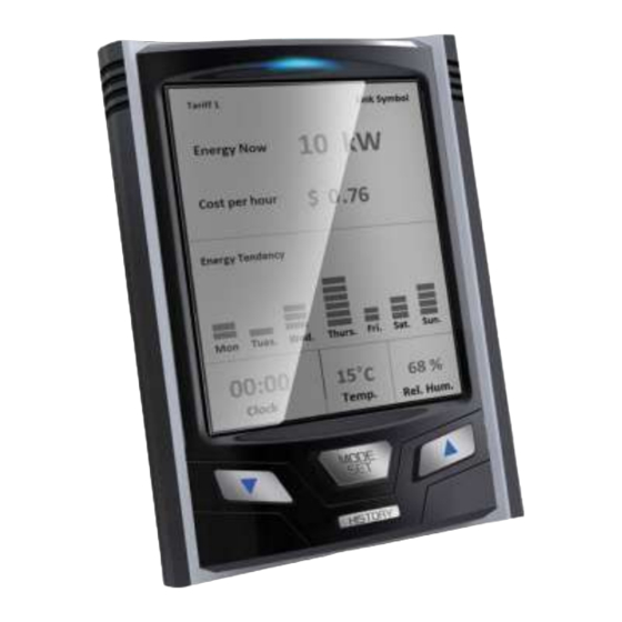
6. Display Screen Information and Clearing Data Soon after successfully pairing the monitor and transmitter, the LCD screen will automatically return to the default display. Furthermore, when there is no button operation (for a period of time), the LCD screen will automatically return to the default screen. Below is an example of the default LCD screen. -
Page 7: Installation / Set-Up
(Please contact a qualified electrician). Regarding three phase supply, a third sensor clamp is needed (sold separately). Please contact MTP Instruments for additional sensors. Installing the sensor clamp to the live wire. First, push the release cap. Second, place it on the correct live wire. - Page 8 Note: It is normal when installing the (detachable) sensor clamp on a live wire, that the sensor emits a vibrating sound when it is not plugged into the transmitter. Once the sensor is connected to the live wire and plugged to the transmitter, the vibrating sound will cease. Note: Detachable sensor clamp can be plugged into any of the two inputs of the transmitter, when making connection.
- Page 9 IMPORTANT NOTICE: Please contact a qualified electrician to carry out the installation. We will not be held responsible for damage as a result of a wrong connection. Please note that monitor displays the Apparent Power (VA) and not the Active Power (watts). Installation on standard 200A panel Unscrew the four corners to remove the electrical panel protection cover.
- Page 10 Installation on a 3 phase 3 wire system Install the two enclosed sensors (100A), as indicated on diagram 1 (phase 1 and phase 3). Connect the two heavy duty sensors to the transmitter. Insert each jack on the end of the white wire into any of the input sockets of the transmitter.
-
Page 11: Linking The Transmitter With The Display
7.2 Linking the Transmitter with the Display 1. Remove the clear plastic tab located on the back of the transmitter (marked: REMOVE BEFORE USING). Removing the plastic tab will power the transmitter and the light on the transmitter will begin to flash. Note : During the linking process, keep the transmitter and monitor as close as possible to each other. -
Page 12: Display Screen Set-Up Instructions
Fig. 7 Fig. 8 Fig. 9 7.3 Display Screen Set-up Instructions While the default screen is displayed (See Fig. 7), press and hold down the SET/MODE key for 3 seconds. Then the red LED light flashes twice, release the SET/MODE key. At this point, the monitor will enter in Setting Mode (See Fig. - Page 13 Currency Setting While in Setting Mode, use the UP or DOWN key to scroll through the options and select the flashing Kr symbol. To access the currency interface, press the SET/MODE key (See Fig. 10). Press the UP or DOWN key to select the desired currency and press the SET/MODE key to confirm and return to the Setting Mode.
- Page 14 Setting a single tariff: While in the Setting Mode, use the UP or DOWN key to scroll through the options and select the flashing TARIFF symbol. Press the SET/MODE key to access the TARIFF selection interface (See Fig. 11). In the TARIFF selection interface, select TARIFF 1 by pressing the SET/MODE key (See Fig.
- Page 15 hour (00-23) and minute (00-59). The confirmation of the minute value will return to the tariff value setting for the second tariff (See Fig. 18). Repeat the same steps to set the tariff value and starting time for the second and third tariff periods.
- Page 16 Time (Clock) Setting While in the Setting Mode, use the UP or DOWN key and scroll to the flashing symbol. To access the clock setting interface, press the SET/MODE key (See Fig. 21). Once in the clock setting interface, the hour value (00-23) will begin flashing and can be adjusted by pressing the UP or DOWN key.
-
Page 17: Operation
Buzzer ON/OFF While in Setting Mode, use the UP or DOWN key to scroll to the flashing symbol. To access the buzzer setting interface, press the SET/MODE key (See Fig. 24). Use the UP or DOWN key to switch between the ON and OFF status. When the buzzer is set to ON, the bell icon will appear on the top right corner of the display screen (See Fig. - Page 18 Fig. 26 Fig. 27 Fig. 28 Switching Data Type (History) When viewing the History (up to now) – See Fig. 26, 27 and 28 – press the SET/MODE key to change the type of data history displayed amongst any of the following options: Energy consumption (kWh) Currency ($) and CO emission (kg CO ).
- Page 19 To view the history data of yesterday, press the DOWN key once. For the history data of before yesterday, press the DOWN key twice and so on. The DOWN key can be pressed up to 7 times, this allows to view the data history of the past 7 days. The date on the display will change to be in accordance with the history data date.
- Page 20 Fig. 34 Fig. 35 Fig. 36 Viewing the history data of the last 24 months From the default screen, click on the HISTORY key three times and notice that "Monthly" will be displayed on the screen (See Fig. 28 – Monthly). The Monthly function stores the past 24 months of data, as well as the accumulated data up to now from 00:00 of the 1 of current month.
- Page 21 Antenna Icon and Sensor Clamp Icon on the display When the monitor successfully receives signals from the transmitter, the antenna icon appears on the top left corner of the display screen. Located beside the antenna icon on the display, is the sensor clamp icon which indicates the number of sensor clamps connected to the transmitter (See Fig.
- Page 22 Only when the total battery power for the transmitter / Sender is below 2.3V will the low battery warning icon appear. The low battery indicator for the transmitter is represented by a battery icon with an "T". The warning icon will flash once every second to remind the user to replace the batteries (See Fig.
-
Page 23: Frequently Asked Questions
Limited Warranty and Limitations of Liability MTP Instruments warrants this instrument to be free of defects in parts and workmanship for one (1) year from date of shipment. This warranty does not apply to defects resulting from action of the user such as misuse, improper wiring, operation outside of specification, improper maintenance or repair, or unauthorized modification. - Page 24 Les Instruments Instruments Head Office 4409 Charleroi street Montreal-North, Quebec H1H 1T6 Telephone: (514) 326-7167 Fax: (514) 326-7835 Toll Free Number: 1-888-326-7167 Web Site : www.mtpinc.com E-mail : info@mtpinc.com Distributed by :...
Need help?
Do you have a question about the MTP-3100 and is the answer not in the manual?
Questions and answers