Sign In
Upload
Download
Table of Contents
Contents
Add to my manuals
Delete from my manuals
Share
URL of this page:
HTML Link:
Bookmark this page
Add
Manual will be automatically added to "My Manuals"
Print this page
×
Bookmark added
×
Added to my manuals
Manuals
Brands
Miele Manuals
Hob
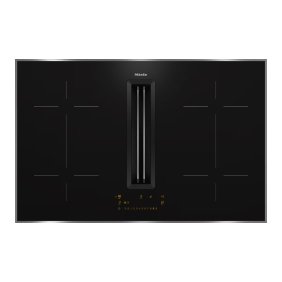
KMDA 7473 FR-A
Operating and installation instructions
Miele KMDA 7473 FR-A Operating And Installation Instructions
Hide thumbs
1
2
Table Of Contents
3
4
5
6
7
8
9
10
11
12
13
14
15
16
17
18
19
20
21
22
23
24
25
26
27
28
29
30
31
32
33
34
35
36
37
38
39
40
41
42
43
44
45
46
47
48
49
50
51
52
53
54
55
56
57
58
59
60
61
62
63
64
65
66
67
68
69
70
71
72
73
74
75
76
77
78
79
80
81
82
83
84
85
86
87
88
89
90
91
92
93
94
95
96
97
98
99
100
101
102
103
104
105
106
107
108
109
110
111
112
page
of
112
Go
/
112
Contents
Table of Contents
Bookmarks
Table of Contents
Table of Contents
Warning and Safety Instructions
Caring for the Environment
Guide to the Appliance
Hob
Controls and Display
Cooking Zones
Accessories Supplied
Before Using for the First Time
Cleaning the Hob for the First Time
Switching on the Hob for the First Time
Using the Vapour Extraction for the First Time
Miele@Home
How It Works
Cooking Zones
Noises
Power Management
Vapour Extraction
Pans
Tips on Saving Energy
Setting Ranges
Operation
Using the Appliance
Switching on the Hob
Setting the Power Level
Changing the Power Level
Switching off a Cooking Zone/The Hob
Residual Heat Indicator
Setting the Power Level - Extended Setting Range
Flex Cooking Area
Auto Heat-Up
Booster Function
Keeping Warm
Vapour Extraction
Timer
Minute Minder
Auto Switch off
Using both Timer Functions at the same Time
Additional Functions
Stop & Go
Recall
Wipe Protection
Demo Mode
Displaying Hob Data
Safety Features
System Lock/Safety Lock
Safety Switch-Off
Overheating Protection
Programming
Note for Test Institutes
Cleaning and Care
Cover Grille/Grease Filter/Charcoal Filter
Removing the Cover Grille
Cleaning the Grease Filter
Replacing the Charcoal Filter (Only KMDA 7473 FR-U, KMDA 7473 FL-U)
Cleaning the Vapour Extraction Drip Tray
Cleaning the Inside of the Fan Unit
Resetting the Grease Filter Operating Hours Counter
Resetting the Charcoal Filter Operating Hours Counter (Only KMDA 7473 FR-U, KMDA 7473 FL-U)
Problem Solving Guide
Messages in the Display
Unexpected Behaviour
Unsatisfactory Results
General Problems or Technical Faults
Optional Accessories
Installation
Safety Instructions for Installation
Safety Distances
Operating Options
Installation Examples
Installation Notes - Surface-Mounted
Installation Dimensions - Surface-Mounted
Kmda 7473 Fr-A, Kmda 7473 Fr-U
Kmda 7473 Fl-A, Kmda 7473 Fl-U
Extraction and Guided Recirculation Mode
Plug&Play Mode
Connection to Window Contact, if Required
Surface-Mounted Installation
Installation Notes - Flush-Fit
Installation Dimensions - Flush-Fit
Kmda 7473 Fl-A, Kmda 7473 Fl-U
Extraction and Guided Recirculation Mode
Plug&Play Mode
Connection to Window Contact, if Required
Flush-Fit Installation
Rear Wall Cut-Out - Without Drilling Template
Ducting
Electrical Connection
After Sales Service
Contact in the Event of a Fault
Data Plate
Warranty
Product Data Sheets
UK Conformity Declaration
Advertisement
Quick Links
1
Guide to the Appliance
2
Installation
3
Installation Examples
4
Electrical Connection
Download this manual
Operating and installation
instructions
Induction hobs
To avoid the risk of accidents or damage to the appliance it is essen-
tial to read these instructions before it is installed and used for the
first time.
en-GB
M.-Nr. 12 294 640
Table of
Contents
Previous
Page
Next
Page
1
2
3
4
5
Advertisement
Table of Contents
Need help?
Do you have a question about the KMDA 7473 FR-A and is the answer not in the manual?
Ask a question
Questions and answers
Related Manuals for Miele KMDA 7473 FR-A
Hob Miele KMDA 7774 Operating And Installation Instructions
Ceramic cooktops with induction (88 pages)
Hob Miele KMDA 7774 Operating And Installation Instructions
Ceramic hobs with induction (92 pages)
Hob Miele KMDA 7774 FL User Manual
Ceramic hobs with inductio (93 pages)
Hob Miele KMDA 7774 FR User Manual
Ceramic hobs with inductio (93 pages)
Hob Miele KMDA 7774-1 Operating And Installation
Ceramic hobs with induction (96 pages)
Hob Miele KMDA 7633 FR Operating And Installation Instructions
(100 pages)
Hob Miele KMDA 7476 FR Operating And Installation Instructions
(100 pages)
Hob Miele KMDA 7272 FR-A Operating And Installation Instructions
(108 pages)
Hob Miele KMDA 7272 FR-U Operating And Installation Instructions
(108 pages)
Hob Miele KMDA 7272 FL-A Operating And Installation Instructions
(108 pages)
Hob Miele KMDA 7272 FL-U Operating And Installation Instructions
(108 pages)
Hob Miele KMDA 7473 FR-U Operating And Installation Instructions
(112 pages)
Hob Miele KMDA 7473 FL-A Operating And Installation Instructions
(112 pages)
Hob Miele KMDA 7473 FL-U Operating And Installation Instructions
(112 pages)
Hob Miele KMDA 7676 Operating And Installation Instructions
(116 pages)
Hob Miele KM 6350 Operating And Installation Instructions
Ceramic hobs with induction (84 pages)
This manual is also suitable for:
Kmda 7473 fr-u
Kmda 7473 fl-a
Kmda 7473 fl-u
Table of Contents
Print
Rename the bookmark
Delete bookmark?
Delete from my manuals?
Login
Sign In
OR
Sign in with Facebook
Sign in with Google
Upload manual
Upload from disk
Upload from URL


Need help?
Do you have a question about the KMDA 7473 FR-A and is the answer not in the manual?
Questions and answers