Miele KMDA 7633 FR Operating And Installation Instructions
Hide thumbs
Also See for KMDA 7633 FR:
- Installation instructions manual (30 pages) ,
- Operating and installation instructions (20 pages)

Related Manuals for Miele KMDA 7633 FR


Summary of Contents for Miele KMDA 7633 FR
- Page 1 Operating and installation instructions Induction hobs To avoid the risk of accidents or damage to the appliance it is essential to read these instructions before it is installed and used for the first time. en-AE, SA M.-Nr. 11 516 840...
-
Page 3: Table Of Contents
Cooking zones..................... 23 Before using for the first time ................24 Cleaning the hob for the first time............... 24 Switching on the hob for the first time ..............24 Miele@home ......................25 Induction ......................28 How it works......................28 Pans........................28 Power management .................... - Page 4 Contents Wipe protection ....................47 Demonstration mode................... 47 Displaying hob data..................... 47 Safety features....................48 System lock / Safety lock..................48 Safety switch-off ....................50 Overheating protection..................51 Programming ..................... 52 Cleaning and care ..................... 56 Grease filter/extraction grille................58 Cooker hood drip tray ..................
- Page 5 Contents Flush-fit installation ..................... 91 Ducting ........................ 92 Electrical connection ................... 93 After sales service..................... 96 Contact in case of malfunction ................96 Data plate ......................96 Guarantee......................96...
-
Page 6: Warning And Safety Instructions
Miele cannot be held liable for injury or damage caused by non- compliance with these instructions. Keep these instructions in a safe place and pass them on to any... - Page 7 Warning and Safety instructions Correct application This hob is intended for domestic use and use in other similar environments. This hob is not intended for outdoor use. It is intended for domestic use only to cook food and keep it warm.
- Page 8 Warning and Safety instructions Safety with children Children under 8 years of age must be kept away from the hob unless they are constantly supervised. Children over 8 years of age may use the hob without supervision if its operation has been clearly explained to them and they are able to use it safely.
- Page 9 Unauthorised installation, maintenance and repairs can cause considerable danger for the user. Installation, maintenance and repairs must only be carried out by a Miele authorised technician. Damage to the hob can compromise your safety. Check the hob for visible signs of damage. Do not use the hob if it is damaged.
- Page 10 Miele authorised technician. Otherwise the warranty is invalidated. Miele can only guarantee the safety of the appliance when genuine original Miele replacement parts are used. Faulty components must only be replaced by Miele spare parts. ...
- Page 11 Warning and Safety instructions In areas which may be subject to infestation by cockroaches or other vermin, pay particular attention to keeping the appliance and its surroundings clean at all times. Any damage caused by cockroaches or other vermin will not be covered by the warranty.
- Page 12 Warning and Safety instructions Using at the same time as other heating appliances that depend on the air from the room Danger of toxic fumes! Great care should be taken when using the cooker hood in the same room or the same area of the house as another heating appliance that depends on the air from the room.
- Page 13 Warning and Safety instructions In order to ensure safe operation and to prevent gases given off by the heating appliance from being drawn back into the room, when the cooker hood and the heater are both operated simultaneously, an underpressure in the room of 0.04 mbar (4 Pa) is the maximum permissible.
- Page 14 Warning and Safety instructions Correct use The hob gets hot when in use and remains hot for a while after being switched off. There is a danger of burning until the residual heat indicators go out. Oil and fat can overheat and catch fire. Do not leave the hob unattended when cooking with oil and fat.
- Page 15 Warning and Safety instructions You could burn yourself on the hot hob. Protect your hands with heat-resistant pot holders or gloves when handling hot pots and pans. Do not let them get wet or damp, as this causes heat to transfer through the material more quickly with the risk of scalding or burning yourself.
- Page 16 Warning and Safety instructions Only use pots and pans with smooth bases. Rough bases will scratch the ceramic glass. Lift pans into position on the hob. Sliding them into place can cause scuffs and scratches. Because induction heating works so quickly, the base of the pan could, under certain circumstances, heat up to the temperature at which oil or fat self-ignites within a very short time.
- Page 17 Warning and Safety instructions If the cookware only partially covers a cooking or extended zone, the handle could become very hot. Always place cookware in the middle of a cooking or extended zone! Deposits of grease and dirt will prevent the cooker hood from working properly.
- Page 18 (see relevant section). Accessories Only use genuine original Miele accessories and spare parts with this appliance. Using accessories or spare parts from other manufacturers will invalidate the guarantee, and Miele cannot accept liability.
-
Page 19: Caring For The Environment
Please dispose of it at your local community waste collection / recycling centre or contact your Miele dealer for advice. Ensure that it presents no danger to children while being stored for disposal. -
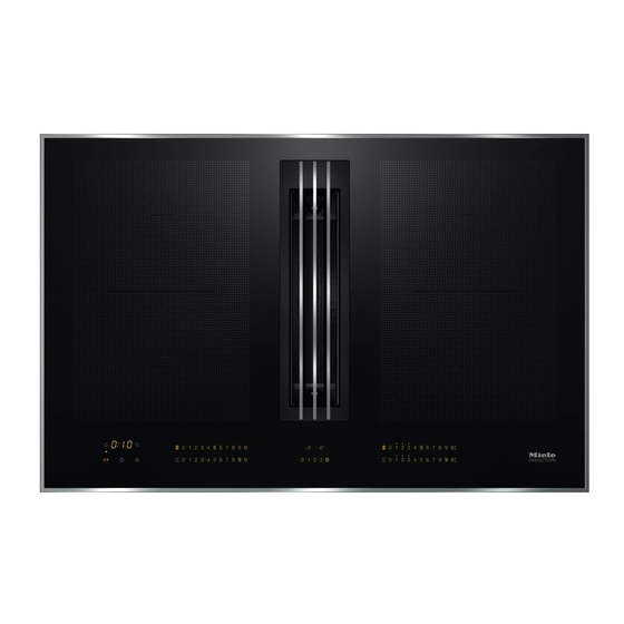
Page 20: Guide To The Appliance
Guide to the appliance a PowerFlex cooking zone cd Can be combined to form a PowerFlex cooking area b PowerFlex cooking zone e Control elements/Indicators ab Can be combined to form a f Cover grille PowerFlex cooking area c PowerFlex cooking zone g Grease filter d PowerFlex cooking zone h Removable drip tray... -
Page 21: Controls And Display
Guide to the appliance Controls and display Cooking zones/Timer Sensor controls a For switching the hob on and off b Stop & Go c Wipe protection d For switching PowerFlex cooking zones on together/separately. e For activating/deactivating the keeping warm function f Numerical keybank For setting power levels/minute minder and switch-off times g Automatic switch-off selector for cooking zones... - Page 22 Guide to the appliance Cooker hood a Numerical keybank for setting the power level b Touch control for the 5 minute run-on option c Touch control for the 15 minute run-on option d Clean grease filter indicator e Reactivate charcoal filter indicator...
-
Page 23: Cooking Zones
Guide to the appliance Cooking zones Cooking Size in cm Max. rating Linked zone cooking in watts for 230 V Ø zone 15–23 19 x 23 Normal 2100 TwinBooster, level 1 3000 TwinBooster, level 2 3650 15–23 19 x 23 Normal 2100 TwinBooster, level 1 3000 TwinBooster, level 2... -
Page 24: Before Using For The First Time
Before using for the first time Please stick the extra data plate for Switching on the hob for the the appliance supplied with this first time documentation in the space provided The metal components have a in the “After sales service” section of protective coating which may give off a this booklet. -
Page 25: Miele@Home
Before using for the first time Miele@home availability Miele@home The ability to use the Miele app Prerequisite: home WiFi network depends on the availability of the Miele@home service in your country. Your hob is equipped with an integrated WiFi module. The hob can be The Miele@home service is not connected to your home WiFi network. - Page 26 Connecting via WPS Prerequisite: you must have a WPS Connecting via the app (WiFi protected setup) compatible The Miele app can be used to connect router. to your network. Switch the hob on. Install the Miele app on your mobile device.
- Page 27 Before using for the first time Cancelling the process Touch any sensor control. Resetting settings Resetting is not required when replacing the router. Switch the hob on. Touch the 0 sensor control on any of the numerical displays. ...
-
Page 28: Induction
Induction How it works Pans An induction coil is located under each Suitable pans induction cooking zone. The coil - stainless steel pans with a magnetic creates a magnetic field that reacts base directly with the base of the pan and heats it up. - Page 29 Induction No pan/unsuitable pan display Tips The set power level flashes in the - To make optimum use of the cooking numerical keybank for the cooking zone zones, choose cookware with a suitable base diameter (see - if the zone has been switched on “Overview –...
-
Page 30: Power Management
Induction If the new cooking zone requires more Power management power than the first cooking zone can The hob has a maximum total permitted provide, this may result in the following power consumption which cannot be consequences for the first cooking exceeded for safety reasons. -
Page 31: Noises
Induction Noises When using an induction hob, the following noises can occur in the pan, depending on what it is made of and how it has been constructed. Buzzing on the higher power settings. This will decrease or cease altogether when the power setting is reduced. -
Page 32: How The Vapour Extraction Works
The necessary This is not necessary here. accessories are available from Miele. The charcoal filter system also appears when the appliance is operated using extraction mode. -
Page 33: Tips On Saving Energy
Tips on saving energy - Use a lid whenever possible to - Clean or replace the filters at regular minimise heat loss. intervals. Heavily soiled filters reduce performance, increase the risk of fire - Select a smaller pan when cooking and are unhygienic. -
Page 34: Setting Range
Setting range The hob is programmed with 9 power levels at the factory. If you wish to fine-tune a setting, you can extend the power setting range to 17 power levels (see “Programming”). Setting range Default Extended setting settings (9 power (17 power levels) levels) -
Page 35: Operation
Operation Using the appliance Malfunction due to dirty and/or covered sensor controls. This ceramic hob is equipped with electronic sensor controls which react If the sensor controls are dirty or covered this could cause them to fail to finger contact. For safety reasons, in order to switch the appliance on, the to react, to activate a function or On/Off ... -
Page 36: Switching On The Hob
Operation Switching off a cooking zone Risk of fire with overheated food. Unattended food can overheat and To switch off a cooking zone, touch catch alight. the 0 sensor for that cooking zone. Do not leave the hob unattended ... -
Page 37: Power Level Setting - Extended Setting Range
Operation Power level setting - Extended setting range Touch the numerical keybank in between two number sensors. The numbers to the left and right of the interim level light up brighter than the others. Example: If you have set power level 7. the numbers 7 and 8 will be brighter than the other numbers. -
Page 38: Powerflex Cooking Area
Operation PowerFlex cooking area (pot) PowerFlex cooking area The PowerFlex cooking zones combine automatically to form a PowerFlex cooking area when you place sufficiently large items of cookware on them (see “Guide to the appliance – Hob”). Settings for the linked cooking area are controlled by the numerical display of the front or left PowerFlex cooking zone (depending on model). -
Page 39: Auto Heat-Up
Operation Auto heat-up Continued Heat-up time cooking setting* [min : sec] When Auto heat-up has been activated, the cooking zone switches on Approx. 0:15 automatically at the highest setting and Approx. 0:15 then switches to the continued cooking setting which you have previously Approx. -
Page 40: Booster Function
Operation Activating the TwinBooster Booster function The cooking zones are equipped with a Level 1 TwinBooster. Place the cookware on the cooking When the Booster function is activated, zone you want to use. the power is boosted so that large ... -
Page 41: Keeping Warm
Operation Activating/deactivating the keeping Keeping warm warm function This function is for keeping food warm Touch the sensor for the cooking which has just been cooked and is still zone you wish to use. hot. It is not for reheating food that has gone cold. -
Page 42: Extractor
Operation Power level setting / Switching off Extractor To switch the fan on touch the The extractor will switch itself on appropriate sensor for the power automatically if a there is a pan on a level you want. cooking zone and a power level has been set for that zone (Con@ctivity). - Page 43 Operation Run-on time It is advisable to run the fan for a few minutes after cooking has finished. This helps to neutralise any lingering vapours and odours in the air. The following two options are available: (5 minutes) and (15 minutes). The run-on duration will be carried out using the power level set during activation.
-
Page 44: Timer
Timer The hob has to be switched on if you The functions can be used at the same want to use the timer. time. The shortest time is always displayed and the sensor control A duration of between 1 minute (:) and 9 hours 59 minutes (:) can be (minute minder) or the indicator light of set. -
Page 45: Switching Off A Cooking Zone Automatically
Timer sensor control repeatedly until the Switching off a cooking zone indicator light for the zone you require automatically flashes. You can set a time after which a Changing the switch-off time cooking zone will switch off automatically. This function can be ... -
Page 46: Additional Functions
Additional functions Stop & Go Recall When Stop & Go is activated, the power If the hob is switched off in error during of all cooking zones in use is reduced to operation, this function can be used to power level 1. The power level of the reset all settings. -
Page 47: Wipe Protection
Additional functions Wipe protection Displaying hob data The model number and software The hob sensors can be locked for version of the hob can be displayed. 20 s in order, for example, to remove There must not be any pots or pans on soiling. -
Page 48: Safety Features
Safety features The safety lock is activated when the System lock / Safety lock hob is switched on. When the safety The lock function is deactivated if lock is activated, the hob can be there is a break in the mains supply. operated only under certain conditions: - The cooking zones, the cooker hood Your hob is equipped with a system... - Page 49 Safety features Activating the safety lock Touch and hold the and sensors at the same time for 6 seconds. The seconds can be seen counting down in the timer display. When this time has elapsed will appear in the timer display.
-
Page 50: Safety Switch-Off
Safety features Safety switch-off Power level* Maximum operating time [h:min] Sensor controls are covered Safety setting Your hob will turn off automatically if one or several of the sensors remain 10:00 8:00 5:00 covered for longer than 10 seconds, for example, by finger contact, food boiling 10:00 7:00... -
Page 51: Overheating Protection
If, despite removing the cause, the - The set power level will be reduced. overheating protection mechanism triggers again, contact your Miele - The cooking zone switches off dealer. automatically. flashes in the timer display alternating with . -
Page 52: Programming
Programming You can adapt the programming of the To save the settings hob to your personal needs. Several While the programme is showing in settings can be altered in succession. the display (e. g. :) touch the sensor until the indicators go out. After accessing programming mode, the symbol appears and ... - Page 53 Programming Settings Programme Code P:01 Demo mode C:00 Demo mode off C:01 Demo mode on P:03 Factory default setting C:00 Do not restore factory default settings C:01 Restore factory default settings P:04 Number of cooking zone power C:00 9 power levels + Booster levels C:01 17 power levels + Booster...
- Page 54 C:03 Connection possible via WPS push button C:04 WiFi reset to default (C:00) Direct WiFi connection of hob and C:05 external cooker hood without Miele app (Con@ctivity 3.0) P:12 Sensor controls reaction speed C:00 Slow C:01 Normal C:02...
- Page 55 Programming Settings Programme Code P:25 Keeping warm temperature C:00 50 °C 55 °C C:01 C:02 60 °C 65 °C C:03 C:04 70 °C 75 °C C:05 C:06 80 °C 85 °C C:07 C:08 90 °C Unlisted programmes are not assigned. The factory-set code is shown in bold. After the hob has been switched on appears in the timer display for a few seconds. In the text and charts, the extended power levels are shown with a dot after the number for better understanding.
-
Page 56: Cleaning And Care
Cleaning and care Clean the hob after every use. Risk of burning due to hot cooking zones. Dry the hob thoroughly after cleaning with water to avoid limescale residue. The cooking zones will be hot after use. Unsuitable cleaning agents Switch the hob off. - Page 57 Then carefully scrape off these residues immediately whilst they are Then clean the ceramic glass surface still hot, using a scraper blade with the Miele ceramic and stainless suitable for use on glass. steel hob cleaner (see “optional accessories”) or with a proprietary ...
-
Page 58: Grease Filter/Extraction Grille
Cleaning and care Removing the grease filter Grease filter/extraction grille Lift up the extraction grille. The extraction grille and the reusable metal grease filter in the vapour Remove the grease filter carefully. Do extraction fan collect solid matter from not let the grease filter tip over. -
Page 59: Cooker Hood Drip Tray
Cleaning and care Cleaning the extraction grille and the Cooker hood drip tray grease filter by hand Clean the drip tray if liquid from food Clean the extraction grille and the being spilled or boiling over has got into grease filter with a soft nylon brush in the cooker hood. -
Page 60: Resetting The Grease Filter Operating Hours Counter
Cleaning and care Resetting the grease filter operating hours counter After cleaning the grease filter, the operating hours counter needs to be reset. Touch the sensor for 3 seconds. The sensor will go out. Reactivating charcoal filter The charcoal filter needs to be reactivated after 120 operating hours. -
Page 61: Problem Solving Guide
There is no power to the hob. zones will not switch Check if the mains fuse has tripped. Contact a qualified electrician or your Miele dealer (for the minimum fuse rating, see data plate). There may be a technical fault. - Page 62 Problem solving guide Issue Cause and remedy The hob has switched One or more of the sensor controls are covered, e.g. off automatically. When by finger contact, food boiling over or an object. the element is switched Clean off any dirt and/or remove the object (see back on, ...
- Page 63 Disconnect the hob from the mains electricity timer display and the supply. buzzer is sounding. Contact your Miele dealer. The hob must be connected to the mains according to the wiring diagram. “E” and a number, Cooking zone fault e.g. 1–0, is flashing...
- Page 64 Problem solving guide Issue Cause and remedy Liquid has got into the Due to boiling over or spillage, liquid has made its cooker hood. way through the extraction grille into the cooker hood. The base of the grease filter can hold approx. 250 ml of liquid.
-
Page 65: Optional Accessories
Ceramic and stainless steel hob and conditioning products for your cleaner 250 ml Miele appliances. These can be ordered from your Miele dealer (see end of this booklet for contact details). Removes heavy soiling, limescale Pans deposits and aluminium residues Miele offer a wide range of cookware. -
Page 66: Installation
(e.g. a drawer) or be subject to mechanical obstruction which could damage it. Observe carefully the safety clearances listed on the following pages. Exhaust ducting must be of non-inflammable material. Suitable material is available from your Miele dealer. - Page 67 *INSTALLATION* Installation The appliance must not be connected to a chimney or flue which is in use. Neither should it be connected to ducting which ventilates rooms with fireplaces. If exhaust air is to be extracted into a chimney or ventilation duct no longer used for other purposes, seek professional advice.
-
Page 68: Safety Distances
*INSTALLATION* Installation Safety distances Safety distance above the hob The safety distance specified by the manufacturer of the cooker hood must be maintained between the hob and the cooker hood above it. If combustible objects are installed above the hob (e.g., cabinets, utensil rail, etc.), a minimum safety distance of 600 mm must be maintained. - Page 69 *INSTALLATION* Installation Safety distances to the sides and back of the appliance It is advisable to install the hob with plenty of space either side of it. The minimum distance shown below must be maintained between the back of the hob and a tall unit or wall. The minimum distance , ...
- Page 70 *INSTALLATION* Installation Safety distance when installing the appliance near a wall with additional niche cladding A minimum safety distance must be maintained between the worktop cut-out and any niche cladding to protect it from heat damage. If the niche cladding is made from a combustible material (e.g. wood) a minimum safety distance ...
-
Page 71: Installation Notes
*INSTALLATION* Installation Tiled worktops Installation notes All dimensions are given in mm. Surface-mounted installation Seal between the hob and the worktop Grout lines and the hatched area underneath the hob frame must be smooth and even. If they are not the hob will not sit flush with the worktop and the sealing strip underneath the hob will not provide a good seal... -
Page 72: Flush-Fit Installation
*INSTALLATION* Installation Flush-fit installation Natural stone worktops The hob is set directly in the cut-out. Flush-fit installation is only possible in natural stone (granite, marble), solid Solid wood worktops, tiled worktops, wood and tiled worktops. Certain glass worktops models are suitable for building into The hob is secured inside the cut-out glass worktops –... -
Page 73: Installation Examples
*INSTALLATION* Installation Installation examples Recirculation mode Extraction mode... -
Page 74: Installation Dimensions - Surface-Mounted
*INSTALLATION* Installation a Front Installation dimensions – Surface-mounted b Removable drip tray c Mains connection box with mains KMDA 7633 FR, KMDA 7634 FR connection cable, L = 1440 mm d Air duct connection – at the back (ex-works) e Air duct connection – on the right (conversion required) f Air duct connection –... - Page 75 *INSTALLATION* Installation KMDA 7633 FL, KMDA 7634 FL a Front b Removable drip tray c Mains connection box with mains connection cable, L = 1440 mm d Air duct connection – at the back (ex-works) e Air duct connection – on the right (conversion required) f Air duct connection –...
-
Page 76: Worktop Depth 600 Mm
*INSTALLATION* Installation Worktop depth 600 mm KMDA 7633 FL, KMDA 7634 FL KMDA 7633 FR, KMDA 7634 FR a Housing unit back panel The housing unit back panel must be a Housing unit back panel removable for service work. The The housing unit back panel must be housing unit wall and an adjoining removable for service work. - Page 77 *INSTALLATION* Installation Extraction to the rear (standard) Extraction to the right Extraction to the left...
-
Page 78: Worktop Depth Greater Than 600 Mm
*INSTALLATION* Installation Worktop depth greater than 600 mm KMDA 7633 FL, KMDA 7634 FL KMDA 7633 FR, KMDA 7634 FR a Housing unit back panel The housing unit back panel must be a Housing unit back panel removable for service work. The The housing unit back panel must be housing unit wall and an adjoining removable for service work. - Page 79 *INSTALLATION* Installation Extraction to the rear (standard) Extraction to the right Extraction to the left...
-
Page 80: Installation Dimensions - Flush-Mounted
*INSTALLATION* Installation a Front Installation dimensions – Flush-mounted b Removable drip tray c Mains connection box with mains KMDA 7633 FL, KMDA 7634 FL connection cable, L = 1440 mm d Stepped cut-out e Wooden frame (to be provided on site) f Air duct connection – at the back (ex-works) g Air duct connection –... -
Page 81: Worktop Depth 600 Mm
*INSTALLATION* Installation Worktop depth 600 mm KMDA 7633 FL, KMDA 7634 FL a Housing unit back panel The housing unit back panel must be removable for service work. The housing unit wall and an adjoining room wall or a piece of furniture must be at least 110 mm apart to ensure sufficient room for the ducting. - Page 82 *INSTALLATION* Installation Extraction to the rear (standard) Extraction to the right Extraction to the left...
-
Page 83: Worktop Depth Greater Than 600 Mm
*INSTALLATION* Installation Worktop depth greater than 600 mm KMDA 7633 FL, KMDA 7634 FL a Housing unit back panel The housing unit back panel must be removable for service work. The housing unit wall and an adjoining room wall or a piece of furniture must be at least 110 mm apart to ensure sufficient room for the ducting. - Page 84 *INSTALLATION* Installation Extraction to the rear (standard) Extraction to the right Extraction to the left...
-
Page 85: Extraction Direction Modification
*INSTALLATION* Installation Extraction direction modification If you modify the extraction direction, the original brackets will no longer be required. Use the bracket provided separately with the cooker hood once the Undo the fixing bracket. extraction direction has been modified. -
Page 86: Turning The Extraction Ducting Connection Anticlockwise
*INSTALLATION* Installation Turning the extraction ducting connection anticlockwise Place the hob on its ceramic surface on a soft underlay. Rotate the fan by 90°. Secure the fan again (you only need 4 screws). Make sure that the plastic edge is on the left. - Page 87 *INSTALLATION* Installation Use the bracket supplied separately to secure the fan. Place the cooker hood onto the drip Lift the frame and the fan and turn it tray again and secure the tray using 180°. the 4 catches. ...
-
Page 88: Connection To Window Contact, If Required
*INSTALLATION* Installation Connection to window contact, if required The window contact connection is live! Danger of electric shock! Disconnect the hob from the mains electricity supply before connecting the switching mechanism. The connection cable for the switching system must only be connected by a suitably qualified and competent electrician. - Page 89 *INSTALLATION* Installation Exchange the bridge for the connection cable of the switching system. Close the casing. Tighten the strain relief screw. Reinsert the plug.
-
Page 90: Surface-Mounted Installation
*INSTALLATION* Installation Surface-mounted installation Create the worktop cut-out. Remember to maintain the minimum safety distances (see “Installation – Safety distances”). Seal any cut surfaces on wooden worktops with a special varnish, silicone sealant or resin to prevent the wood from swelling as a result of moisture ingress. -
Page 91: Flush-Fit Installation
*INSTALLATION* Installation Flush-fit installation Create the worktop cut-out. Remember to maintain the minimum safety distances (see “Safety distances”). Solid wood, tiled and glass worktops: Fix a wooden frame 5.5 mm below the top edge of the worktop (see building-in diagram for “Flush-fit installation”). -
Page 92: Ducting
*INSTALLATION* Installation Ducting If the cooker hood is used at the same time as a heating appliance that relies on oxygen from the same room, there is a risk of toxic fumes. It is essential that the “Warning and safety instructions”... -
Page 93: Electrical Connection
The connection data is quoted on the maintenance and repairs can cause data plate. Please ensure these match considerable danger for the user. the household mains supply. Miele cannot be held liable for Please see wiring diagrams for damage or injury caused by connection. unauthorised installation,... - Page 94 A suitable Switch the lever from 1 (on) to 0 (off). connection cable is available from your Residual current device (RCD) Miele dealer. Switch the main switch from 1 (on) to 0 (off) or press the test button.
- Page 95 *INSTALLATION* Installation Wiring diagram a b c d e 200-240 V~ 200-240 V~ 200-240 V~ (L3) 200-240 V~ 200-240 V~ b c d (L2) 200-240 V~...
-
Page 96: After Sales Service
In the event of any faults which you cannot remedy yourself, please contact your Miele dealer. Contact details for your Miele dealer are given at the end of this document. Please note that telephone calls may be monitored and recorded for training purposes and that a call-out charge will be applied to service visits where the problem could have been resolved as described in this booklet. - Page 99 Tel. +966 11 2013501, Fax. +966 11 2013502 Taif Hadiya Street Tel. +966 12 7327001, Fax. +966 12 7369596 Khobar Al Zahran Road Tel. +966 13 8646150, Fax. +966 13 8646190 Manufacturer: Miele & Cie. KG, Carl-Miele-Straße 29, 33332 Gütersloh, Germany...
- Page 100 KMDA 7633 FR, KMDA 7633 FL, KMDA 7634 FR, KMDA 7634 FL en-AE, SA M.-Nr. 11 516 840 / 01...
Need help?
Do you have a question about the KMDA 7633 FR and is the answer not in the manual?
Questions and answers