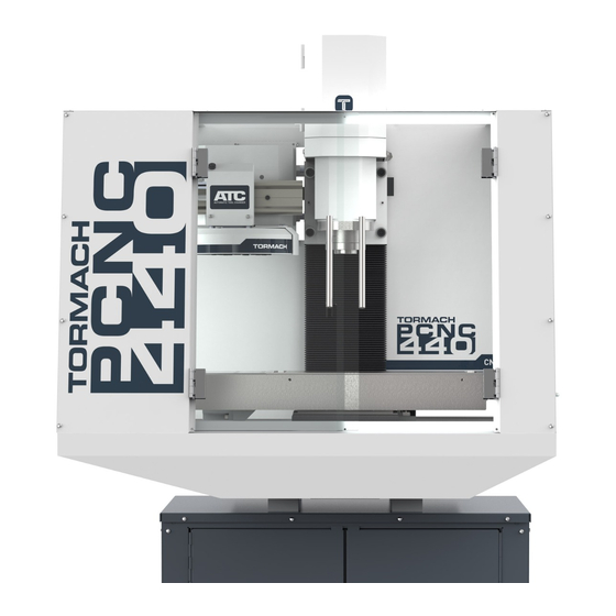
Tormach PCNC 440 Installation Manual
Hide thumbs
Also See for PCNC 440:
- Operator's manual (183 pages) ,
- Technical document (29 pages) ,
- Installation manual (21 pages)
Advertisement
Quick Links
Advertisement

Related Manuals for Tormach PCNC 440


Summary of Contents for Tormach PCNC 440
- Page 1 TECHNICAL DOCUMENT Version 0123A INSTALLATION GUIDE PCNC 440 STAND Page 1...
-
Page 2: Product Information
PCNC 440 Machine Stand, Door Hinge Assembly (PN 51496) Screw, Button Head Cap, Flanged M05× 0.8 × 010, 18-8 Stainless (PN 38205) Note: If any items are missing, we can help. Create a support ticket with Tormach Technical Support at tormach.atlassian.net/servicedesk for guidance on how to proceed. - Page 3 Figure 1: Attaching the legs to the two side panels. Page 3 ©Tormach® 2023 tormach.com Specifications subject to change without notice. TD10809: Installation Guide: PCNC 440 Stand (0123A)
- Page 4 3. Use eight M5 × 0.8 - 10 screws to attach the lower shelf to the two side panels and the back panel. Figure 3: Lower shelf attached to the two side panels and the back panel. Page 4 ©Tormach® 2023 tormach.com Specifications subject to change without notice. TD10809: Installation Guide: PCNC 440 Stand (0123A)
- Page 5 5. Use 10 M5 × 0.8 - 10 screws to attach the front panel to the two side panels and the lower shelf. Figure 5: Front panel attached to the two side panels and the lower shelf. Page 5 ©Tormach® 2023 tormach.com Specifications subject to change without notice. TD10809: Installation Guide: PCNC 440 Stand (0123A)
- Page 6 Figure 7: Attaching the door locks to the doors. 8. Put four mounting blocks on the top panel, aligning each with the pre-drilled holes on the top panel. Page 6 ©Tormach® 2023 tormach.com Specifications subject to change without notice. TD10809: Installation Guide: PCNC 440 Stand (0123A)
- Page 7 13. Use one M12 × 20 mm socket head cap screw and one M12 flat washer to secure the ends of the upper supports to each corner of the top panel. Page 7 ©Tormach® 2023 tormach.com Specifications subject to change without notice. TD10809: Installation Guide: PCNC 440 Stand (0123A)
- Page 8 Figure 9: Upper support and top panel corner assembly. 15. Use 12 M5 × 0.8 - 10 screws to attach the top panel. Figure 10: Top panel attached. Page 8 ©Tormach® 2023 tormach.com Specifications subject to change without notice. TD10809: Installation Guide: PCNC 440 Stand (0123A)
- Page 9 22. Set Machine Stand down on the cardboard that you put on the floor in Step 22. 23. Put one M12 nut on each of the four leveling feet. Page 9 ©Tormach® 2023 tormach.com Specifications subject to change without notice. TD10809: Installation Guide: PCNC 440 Stand (0123A)
- Page 10 25. Lift the Machine Stand off the floor, and set it down on its feet. 26. (Optional) Level the feet as needed. Page 10 ©Tormach® 2023 tormach.com Specifications subject to change without notice. TD10809: Installation Guide: PCNC 440 Stand (0123A)
-
Page 11: Exploded Views And Parts Lists
EXPLODED VIEWS AND PARTS LISTS EXPLODED VIEWS AND PARTS LISTS Complete the following steps in the order listed: Exploded View Parts List Exploded View Page 11 ©Tormach® 2023 tormach.com Specifications subject to change without notice. TD10809: Installation Guide: PCNC 440 Stand (0123A) - Page 12 Parts List Description Quantity PCNC 440 Machine Stand, Back Panel (PN 51484) PCNC 440 Machine Stand, Right Side Panel (PN 51483) PCNC 440 Machine Stand, Leg Weldment (PN 51493) PCNC 440 Machine Stand, Bottom Shelf (PN 51485) PCNC 440 Machine Stand, Upper Shelf (PN 51486) PCNC 440 Machine Stand, Bottom Stiffener (PN 51494)
Need help?
Do you have a question about the PCNC 440 and is the answer not in the manual?
Questions and answers