Table of Contents
Advertisement
Available languages
Available languages
Quick Links
Advertisement
Chapters
Table of Contents

Related Manuals for Lexor PRIVE PEDICURE SPA


Summary of Contents for Lexor PRIVE PEDICURE SPA
-
Page 2: Table Of Contents
THE KEY TO SALON SUCCESS PRIVE PEDICURE SPA USER MANUAL RECEIVING AND INSPECTION: If missing parts or damages are found, please notify the carrier at once and insist on a notation of the damage on the bill of lading. DO NOT DISCARD THE SHIPPING BOX. If you give the carrier a clear receipt for goods that have been damaged in transit, you do so at your own risk and expense. -
Page 3: Identifying Parts For Prive® Model
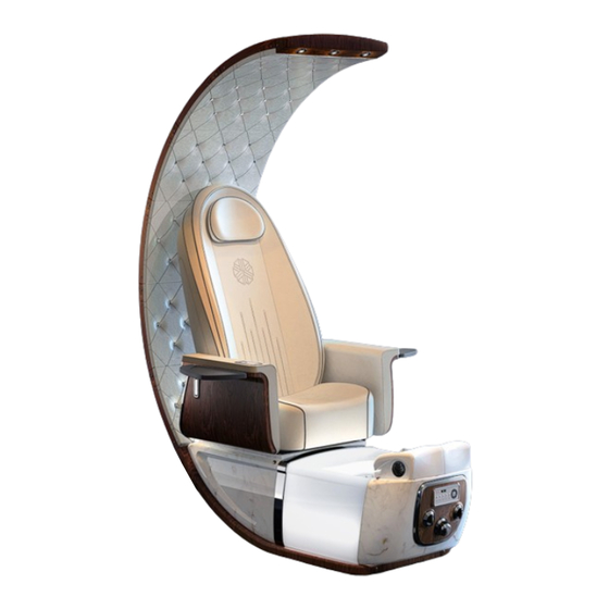
IDENTIFYING PARTS Identifying Parts for PRIVE® Model Pedicure Spa with Massage System 1. Dome spotlight 11. Hot/Cold water mixer valve 2. Dome 12. Auto-fill/Jet knob 3. Pillow 13. Aurora bowl 4. Back cushion with massage 14. Handbag (purse) hook 5. Massage remote control 15. -
Page 4: Wall Clearance & Spa To Spa Recommended Clearance
INSTALLATION WALL CLEARANCE & SPA TO SPA RECOMMENDED CLEARANCE VERY IMPORTANT:The wall clearance for dome-to-wall 0.5 inch / 1.25cm and base-to-wall 10 inch / 25.4cm are mandatory to give enough space for the unobstructed chair recline and plumbing system connections. Failure to follow may result in serious damage to the spa component and void the warranty. -
Page 5: Installation Of Pedicure Spa Dome
INSTALLATION INSTALLATION OF PEDICURE SPA DOME 1. LOWER DOME ASSEMBLY 2 M8 x 45 bolts Step 1: Install lower-dome by inserting 2 mounting rods from lower dome into spa base frame then secure 2 M8 x 45 bolts (attached on base). Locate and connect both ends of spotlight power cables. -
Page 6: Installation Of Pedicure Spa Seat
INSTALLATION INSTALLATION OF PEDICURE SPA SEAT 1. FOLD & UNFOLD BACK-REST MASSAGE “CLICK” Raise the backrest until a “click” is heard. Make sure the lever is locked before operating. To fold down the backrest: Lift up lever handle and push the backrest downward. - Page 7 INSTALLATION 2. BACK CUSHION ASSEMBLY Install the back cushion by engaging the 2 bottom hooks of cushion onto the shaft of massage frame. Position the top of back cushion, then snap the fit joint of back cushion to the crossbar of massage frame, press the back cushion firmly on the massage frame to secure it.
- Page 8 INSTALLATION 4. ARMRESTS ASSEMBLY A. Armrests Assembly Position and line up both markers of the armrest and seat frame connectors. Engage both sides into guide joints. Horizontally rotate armrest counter clockwise (clockwise with right armrest) to lock it in place. Connect 2 connector labeled “1”...
-
Page 9: Installation Of Plumbing System
PLUMBING SYSTEM INSTALLATION OF PLUMBING SYSTEM NOTE: The drainage and water supply system installation require a licensed plumber. Detailed instructions can be found in the manual book. Instructions and local plumbing codes need to be carefully complied to pass the city inspections. 1. - Page 10 PLUMBING SYSTEM 2. POWER DRAIN ¾” PVC drain ½” ID cold water ½” ID hot water ¾” drain pipe ¾” coupling Check valve The power drainage installation should comply with SECTION 807.1, 2018 UPC. P-trap, vent, and connectors should comply with SECTION 1001.1 and 1001.2 UPC. An alternative code needs to be complied with by the states not adopting UPC.
- Page 11 PLUMBING SYSTEM 3. DRAIN SYSTEM RECOMMENDATION Wall ¾” to 1-½” T-connector Connect to main drain Height needs to be adjusted Based on your salon setup 1-½” drain pipe Check valve Detail A 4. HOT/COLD WATER SUPPLY SYSTEM NOTE: The drainage and water supply system installation require a licensed plumber. Instructions and local plumbing codes need to be carefully complied to pass the city inspections.
-
Page 12: Installation Of Ventilation System (Optional)
HỆ THỐNG THÔNG KHÍ VENTILATION SYSTEM INSTALLATION OF VENTILATION SYSTEM (OPTIONAL) (The spa comes with a preinstalled ventilation system.Please contact your state department for the requirements and regulations). 1-1/2” Vent pipe kit supplied. 1-1/2” Vent pipe (pre-installed in spa base). Connect the 2 vent pipes as needed. -
Page 13: Electrical And Pedicure Spa Component Specifications
SPECIFICATIONS ELECTRICAL AND PEDICURE SPA COMPONENT SPECIFICATIONS All electrical connections MUST be made by a licensed electrician following Local & National Electrical and Building Codes. SPECIFICATIONS LIST FOR PRIVE SPA CHAIR Spa : L=71”(180cm) W=31”(79cm) w/ Tray =49”(126cm) H=84”(214cm) Net Weight: ~ 310 lbs. -
Page 14: Pre-Operational Setup
OPERATION & CARE PRE-OPERATIONAL SETUP 1. STEAMER SET UP Installing Air Tube to Air Ring Turn safety cap cover clockwise to open the safety device, next Insert the Air Tube into the safety device. Air Ring Air Tube Select 1 of the 2 applications below as needed: 1. - Page 15 OPERATION & CARE PRE-OPERATIONAL SETUP Drain Stopper Air-Ring Liner Eco-Jet Silicon Pipe Safety Device For Steamer The system should be set as the picture above before each service section. Note: To assure the safety for the operator; if the silicon pipe is not connected or accidentally popped out from the safety connector.
-
Page 16: Operate Auto-Fill /Jet Switch
OPERATION & CARE OPERATE AUTO-FILL /JET SWITCH Digital Control Panel Control Panel Locate the control panel at the front of the spa base. Drain Hot/Cold Auto Fill / Knob Follow the instructions below to operate the pedicure spa. Water Knob Jet switch On/Off Push Button... -
Page 17: Operate Digital Control Panel
OPERATION & CARE OPERATE DIGITAL CONTROL PANEL On/Off Water temp in basin Seat Movement Steam Heat System status Control Up/Down Backward/Forward Recline/Incline On/Off Eco-Jet On/Off Massage Bowl Light Spot Light - Turn on: Click by hand (or by Autofill On) - 1st click: Comfortable light - Select color: Click unit satisfied - 2nd click: Bright light... -
Page 18: Reset Water Sensor And Water Level
OPERATION & CARE RESET WATER SENSOR AND WATER LEVEL 1. RESET WATER SENSOR (EMPTY BASIN BEFORE ACTIVATING THIS MODE) 1. Press & Hold 2. Status screen 3. Click to confirm: “Whirlpool” button for will display will blink if the 3 sec reset is successful - No blink if failed A reset water sensor is required when the water level is out of range. - Page 19 OPERATION & CARE 3. ADJUST THE STEAMER TIMEOUT (Turn off all system functions for configuration) 1. Press & Hold for 3 sec. The LED will display Click until appears on the screen 2. LED screen will display 4. Click to confirm: the current setting - Display will blink if successful - No blink if fail...
-
Page 20: Massage System & Remote Controller
OPERATION & CARE MASSAGE SYSTEM & CONTROLLER 1. Press Auto Button to start Auto mode.Within 10 seconds from start-up there will be 2 options (relax/vigor) by pressing the 'AUTO' button one more time. 2. Press any button (Rolling/Spot, Kneading, Tapping,Combine) to enter Manual mode 3. -
Page 21: Dome Spotlight Replacement
REPLACEMENT DOME SPOTLIGHT REPLACEMENT Remove the 2 mounting screws on Disconnect Spotlight cable connector as both sides of the top dome cover. needed. Remove the Spotlight by lifting the springs holder and push down the Spotlight housing. Reverse the above steps to reinstall the Spotlight. -
Page 22: Steamer Replacement
REPLACEMENT STEAMER REPLACEMENT 1. REMOVE THE LEFT SIDE PANEL Swing up the left armrest Unscrew the 2 thumbscrews as indicated in the above figure Remove the side panel by lift the panel out of the holder then pull out the panel. 2. -
Page 23: Af-Control Box Replacement
REPLACEMENT AF-CONTROL BOX REPLACEMENT 1. REMOVE THE RIGHT SIDE PANEL Swing up the right armrest. Unscrew the 2 thumbscrews as indicated in the above figure. Remove the side panel by lift the panel out of the holder then pull out the panel. 2. - Page 24 REPLACEMENT 3. WIRING DIAGRAM AF-CONTROL BOX Power plug 3 prong Steamer (WHITE) Power plug 2 prong Air Pump (BLACK) Power socket Steamer Out Power socket Air Pump (WHITE) (BLACK) Female power plug (BLACK) AUTO-FILL3 Power socket Whirlpool (BLACK) Power socket Drain Pump (BLUE) Power plug 2 prong Drain...
-
Page 25: Drain Knob & Auto-Fill /Jet Knob
REMOVAL INSTRUCTIONS REMOVING THE DRAIN KNOB & THE AUTO-FILL/JET KNOB 1. REMOVING THE DRAIN KNOB. Step 1. Pull out part 1. Step 2. Loosen(do not remove) 3 black screws (note: there are 3 black screws interspersed with 3 white screws).Then, remove part 2 from the front panel. Step 3. -
Page 26: Removing The Front Panel
REMOVAL INSTRUCTIONS REMOVING THE FRONT PANEL Step 1: Remove the digital control panel by hand.Then, remove all the signal wire connectors at the digital control panel. Digital control panel Step 2: Remove the 2 mounting screws of the front panel. Front panel... -
Page 27: Faucet Assembly Instruction
FAUCET ASSEMBLY INSTRUCTION Faucet Assembly Instruction Cartridge Cartridge arm Step 4: Remove 3 screws and remove cartridge ( Fig.4) Faucet handle Plastic nut Fig .4 Step 2: Remove mounting screw Step 3: Insert socket tool into faucet body Step 1: To open cap cover , use a pointed object and remove push button ( Fig.2). -
Page 28: Removing The Footrest
REMOVAL INSTRUCTIONS REMOVING THE FOOTREST. STEP 1. 1. Pull out & remove the spout and do not let the hose drop into the bottom base. 2. Raise the calf suport. 3. Remove the screw on font of footrest. STEP 2. Lift up the footrest &... -
Page 29: Warning
MISCELLANEOUS WARNING: YOU MUST ALWAYS REFER TO YOUR STATE OR LOCAL GUIDELINES FOR CLEANING REQUIREMENTS, OVERNIGHT SOAKING WITH OVERDOSED CHLORINE MAY DAMAGE RUBBER PART IN BASIN Operation and C CLEANING PROCEDURE IS REQUIRED BY STATE BOARDS Note: *** A cleaning log should be kept with each pedicure spa *** Each State will have slight differences in cleaning policies, please check with your state’s Bureau of Barbering and Cosmetology or Regulatory Authority for specific details. - Page 30 Customers must inspect the shipment to make sure there are no damages prior to signing the Bill of Lading ( BOL - provided by the trucking company). If there is any damage to the shipment, please notate it on the BOL before signing it and contact Lexor’s Customer Support immediately for making a damage report.
- Page 31 UL US & CANADA CERTIFICATIONS ,Prive...
- Page 32 THE KEY TO SALON SUCCESS HƯỚNG DẪN SỬ DỤNG GHẾ PRIVE PEDI SPA NHẬN VÀ KIỂM TRA: Nếu phát hiện thấy các bộ phận bị thiếu hoặc hư hỏng, vui lòng thông báo cho người vận chuyển ngay lập tức và yêu cầu ghi rõ về thiệt hại trên vận đơn. KHÔNG VỨT BỎ THÙNG HÀNG. Nếu bạn giao biên nhận của hàng bị...
-
Page 33: Các Bộ Phận Chính Của Dòng Ghế Prive
CÁC BỘ PHẬN CHÍNH Các bộ phận chính của dòng ghế PRIVE® Ghế Pedicure Spa với hệ thống Massage 1. Đèn spotlight mái vòm 11. Nắm vặn nước nóng/lạnh 2. Mái vòm 12. Nắm vặn Auto-fill/Jet 3. Gối đầu 13. Chậu Aurora 4. -
Page 34: Hướng Dẫn Khoảng Cách Đặt Ghế
HƯỚNG DẪN LẮP ĐẶT HƯỚNG DẪN KHOẢNG CÁCH ĐẶT GHẾ RẤT QUAN TRỌNG: Khoảng cách tối thiểu giữa mái vòm đến vách tường là 0,5 inch / 1,25cm và từ đế Spa đến tường là 10 inch / 25,4cm cần phải được tuân thủ để đủ khoảng cách cho mái vòm và hệ... -
Page 35: Hướng Dẫn Lắp Đặt Mái Vòm
HƯỚNG DẪN LẮP ĐẶT LẮP ĐẶT MÁI VÒM 1. LẮP MÁI VÒM DƯỚI 2 ốc M8 x 45 Bước 1: Lắp đặt mái vòm dưới bằng cách cắm 2 chốt của mái vòm dưới (có tem’’Lower Dome’’) vào khung đế Spa, sau đó cố định 2 bu lông M8x45 (được gắn sẵn trên đế). Xác định vị trí và kết nối hai đầu cắm của dây đèn Spotlight. -
Page 36: Hướng Dẫn Lắp Đặt Nệm Ghế
HƯỚNG DẪN LẮP ĐẶT LẮP ĐẶT PHẦN NỆM GHẾ 1. GẬP MỞ LƯNG GHẾ MASSAGE “CLICK” Nhấc lưng ghế lên cho đến khi nghe thấy tiếng "tách". Phải đảm bảo chốt khóa đã được khóa lại trước khi vận hành. Để... - Page 37 HƯỚNG DẪN LẮP ĐẶT 2. LẮP NỆM LƯNG Lắp nệm lưng bằng cách gắn 2 móc dưới của nệm vào trục trên khung massage. Định vị phía trên của nệm lưng, sau đó gắn ngàm nhựa của nệm lưng vào thanh ngang của khung massage, ấn chặt nệm lưng vào khung massage để...
- Page 38 HƯỚNG DẪN LẮP ĐẶT 4. LẮP RÁP TAY GHẾ A. Lắp tay ghế Định vị và đặt thẳng hàng vạch đánh dấu trên khớp nối tay ghế và khung ghế. Gắn cả hai bên vào khớp dẫn hướng. Xoay ngang tay ghế ngược chiều kim đồng hồ...
-
Page 39: Hướng Dẫn Lắp Đặt Hệ Thống Thoát Nước
HỆ THỐNG THOÁT NƯỚC LẮP ĐẶT HỆ THỐNG THOÁT NƯỚC LƯU Ý: Việc lắp đặt hệ thống thoát nước và cấp nước phải được thi công với thợ ống nước có bằng hành nghề. Chi tiết hướng dẫn có thể được tìm thấy trong sách hướng dẫn. Hướng dẫn và mã hệ thống ống nước cần phải được tuân thủ... - Page 40 HỆ THỐNG THOÁT NƯỚC 2. HỆ THỐNG THOÁT NƯỚC BẰNG BƠM Ống xả PVC ¾” Dây nước nóng đường kính Dây nước lạnh đường trong 1/2” kính trong ½” Ống xả PVC ¾” Ống nối PVC ¾” Van một chiều Việc lắp đặt hệ...
- Page 41 HỆ THỐNG THOÁT NƯỚC 3. KHUYẾN NGHỊ HỆ THỐNG THOÁT NƯỚC Tường Ống nối T ¾” ra 1-½” Ống nối tới hệ thống xả Chiều cao cần được điều chỉnh nước chính dựa trên thiết kế salon của bạn Ống xả đường kính trong 1-½”...
-
Page 42: Hướng Dẫn Lắp Đặt Hệ Thống Thông Khí (Tùy Chọn)
HỆ THỐNG THÔNG KHÍ LẮP ĐẶT HỆ THỐNG THÔNG KHÍ (TÙY CHỌN) (Ghế spa đi kèm với một hệ thống thông gió được lắp đặt sẵn theo một số quy định của tiểu bang. Mỗi tiểu bang có thể có một số quy định khác nhau. Vui lòng liên hệ với các cơ quan ở tiểu bang của bạn để biết thêm về... -
Page 43: Thông Số Về Điện Và Linh Kiện Ghế Pedi Spa
THÔNG SỐ KỸ THUẬT THÔNG SỐ VỀ ĐIỆN VÀ LINH KIỆN GHẾ SPA Tất cả các mối nối điện PHẢI do kỹ thuật viên về điện thực hiện theo các quy định về điện và xây dựng ở địa phương. CẢNH BÁO: ĐIỀU NÀY VÔ... -
Page 44: Thiết Lập Trước Khi Vận Hành
VẬN HÀNH & BẢO DƯỠNG THIẾT LẬP TRƯỚC KHI VẬN HÀNH 1. THIẾT LẬP HỆ THỐNG XÔNG HƠI Lắp đặt ống dẫn khí vào Air-ring Xoay nắp đậy thiết bị an toàn theo chiều kim đồng hồ để mở thiết bị an toàn, tiếp theo lắp ống dẫn khí... - Page 45 VẬN HÀNH & BẢO DƯỠNG THIẾT LẬP TRƯỚC KHI VẬN HÀNH Nắp chụp (Lọc rác) Air-Ring Liner Eco-Jet Ống hơi silicon Thiết bị an toàn cho hệ thống xông hơi Hệ thống nên được thiết lập như hình trên trước mỗi lần sử dụng dịch vụ. Lưu ý: Để...
-
Page 46: Vận Hành Auto-Fill / Jet Switch
VẬN HÀNH & BẢO DƯỠNG VẬN HÀNH AUTO-FILL / JET SWITCH Bảng điều khiển kỹ thuật số Bảng điều khiển Xem bảng điều khiển ở phía trước đế Spa Nắm Nắm vặn nước Nắm vặn Làm theo hướng dẫn bên dưới để vận hành ghế Spa vặn bộ... -
Page 47: Vận Hành Bảng Điều Khiển Kỹ Thuật Số
VẬN HÀNH & BẢO DƯỠNG VẬN HÀNH BẢNG ĐIỀU KHIỂN KỸ THUẬT SỐ Trạng thái của hệ thống spa Nhiệt độ nước trong chậu On/Off Điều khiển ghế Steam Heat Lên/Xuống Tiến/Lùi Ngả lưng ghế Lên/Xuống On/Off Eco-Jet Bật/Tắt Massage Đèn Chậu Đèn Mái Vòm - On: Nhấp bằng tay (hoặc bằng cách On Auto-Fill) -
Page 48: Thiết Lập Lại Cảm Biến Nước Và Mực Nước
VẬN HÀNH & BẢO DƯỠNG THIẾT LẬP CẢM BIẾN NƯỚC VÀ MỰC NƯỚC 1. THIẾT LẬP LẠI CẢM BIẾN NƯỚC ( xả hết nước trong chậu trước khi kích hoạt chế độ này) 3. Nhấp để xác nhận: 2. Màn hình trạng thái 1.Nhấn và... - Page 49 VẬN HÀNH & BẢO DƯỠNG 3. ĐIỀU CHỈNH THỜI GIAN VẬN HÀNH STEAMER (tắt tất cả các chức năng của hệ thống để cấu hình) 1. Nhấn và giữ trong 3 giây. Đèn LED sẽ hiện thị Nhấn tới khi xuất hiện trên màn hình 2.
-
Page 50: Hệ Thống Massage Và Bộ Điều Khiển Từ Xa
VẬN HÀNH & BẢO DƯỠNG HỆ THỐNG MASSAGE & BỘ ĐIỀU KHIỂN 1. Nhấn nút “AUTO” để bắt đầu chế độ tự động massage. Trong 10 giây kể từ lúc khởi động sẽ có 2 lựa chọn. (Relax/Vigor) bằng cách nhấn nút ‘’AUTO’’ thêm 1 lần nữa. 2. -
Page 51: Hướng Dẫn Thay Thế Đèn Spotlight Mái Vòm
HƯỚNG DẪN THAY THẾ THAY THẾ ĐÈN SPOTLIGHT MÁI VÒM Tháo 2 vít gắn 2 bên hông Ngắt kết nối đầu nối cáp Spotlight nếu cần. của mái vòm trên cùng. Tháo đèn Spotlight bằng cách nâng giá đỡ lò xo và đẩy vỏ đèn Spotlight xuống. Làm ngược lại các bước trên để... -
Page 52: Hướng Dẫn Thay Thế Thiết Bị Steamer
HƯỚNG DẪN THAY THẾ THAY THẾ STEAMER 1. THÁO ỐP HÔNG BÊN TRÁI Xoay tay ghế bên trái lên. Vặn 2 nút vặn như được hướng dẫn trong hình trên. Tháo ốp hông bên bằng cách nhấc ốp hông ra khỏi giá đỡ sau đó kéo ốp hông ra. 2. -
Page 53: Hướng Dẫn Thay Thế Hộp Điều Khiển Auto-Fill
HƯỚNG DẪN THAY THẾ THAY THẾ HỘP ĐIỀU KHIỂN AUTO-FILL 1. THÁO ỐP HÔNG BÊN PHẢI Xoay tay ghế bên phải. Vặn 2 nút vặn như được hướng dẫn trong hình trên. Tháo ốp hông bên bằng cách nhấc bảng ra khỏi giá đỡ sau đó kéo bảng ra. 2. - Page 54 HƯỚNG DẪN THAY THẾ 3. SƠ ĐỒ DÂY HỘP ĐIỀU KHIỂN AUTO-FILL Đầu cắm 3 chấu Steamer (TRẮNG) Đầu cắm 2 chấu Air Pump (ĐEN) Ổ cắm Steamer Out (TRẮNG) Ổ cắm Air Pump (ĐEN) Đầu cắm âm (ĐEN) AUTO-FILL3 Ổ...
-
Page 55: Hướng Dẫn Tháo Nắm Vặn Xả Drain Và Nắm Vặn Auto-Fill
HƯỚNG DẪN THÁO THÁO NẮM VẶN BỘ XẢ NƯỚC VÀ NẮM VẶN AUTO-FILL/JET. 1. THÁO NẮM VẶN BỘ XẢ NƯỚC. - Bước 1. Kéo chi tiết 1 ra. - Bước 2. Nới lỏng (không tháo rời) 3 con vít màu đen (chú ý: có 3 con vít màu đen nằm xen kẽ với 3 con vít màu trắng). -
Page 56: Hướng Dẫn Tháo Bảng Điều Khiển
HƯỚNG DẪN THÁO THÁO BẢNG ĐIỀU KHIỂN Bước 1. Dùng tay gỡ bảng điều khiển kỹ thuật số ra . Sau đó rút toàn bộ dây kết nối tín hiệu ở phía sau bảng điều khiển kỹ thuật số. Bảng điều khiển Kỹ... -
Page 57: Hướng Dẫn Lắp Ráp Faucet
HƯỚNG DẪN LẮP RÁP FAUCET Hướng Dẫn Lắp Ráp Faucet Cartridge Trục Cartridge Bước 4: Tháo 3 con vít và tháo Cartridge (hình 4). Nắm vặn Tán nhựa Hình 4 Bước 2:Tháo vít và tháo nút nhấn Bước 3: Đưa dụng cụ vào thân Faucet để Bước 1: Để... -
Page 58: Hướng Dẫn Tháo Gối Chân
HƯỚNG DẪN THÁO THÁO GỐI CHÂN BƯỚC 1. 1. Rút vòi nước lên và tháo vòi nước. Lưu ý tránh không để ống nước rơi vào trong bồn. 2. Nâng gối chân lên. 3. Tháo vít ở phía trước. BƯỚC 2. Nhấc toàn bộ... - Page 59 ĐIỀU KHOẢN KHÁC CẢNH BÁO: BẠN PHẢI THAM KHẢO CÁC QUY ĐỊNH CỦA ĐỊA PHƯƠNG VÀ TIỂU BANG VỀ NGUYÊN LIỆU VỆ SINH TẨY RỬA. VIỆC NGÂM CHẬU QUA ĐÊM TRONG MỘT LƯỢNG LỚN DUNG DỊCH CHLORINE CÓ THỂ LÀM HƯ HẠI PHẦN NHỰA CỦA CHẬU Operation and C QUY TRÌNH VỆ...
- Page 60 (BOL - do công ty vận tải đường bộ cung cấp). Nếu có bất kỳ thiệt hại nào đối với lô hàng, vui lòng ghi rõ trên BOL trước khi ký tên và liên hệ ngay với bộ phận hỗ trợ khách hàng của Lexor để báo cáo thiệt hại.
Need help?
Do you have a question about the PRIVE PEDICURE SPA and is the answer not in the manual?
Questions and answers