
Related Manuals for highmore Rocko HM-WB001-001


Summary of Contents for highmore Rocko HM-WB001-001
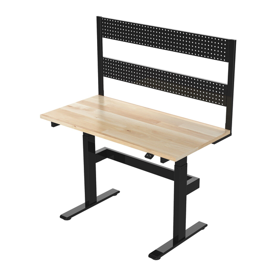
- Page 1 Rocko Motorized Height Adjustable Workbench With Pegboard User Manual Product Ref-HM-WB001-001 Imported By: Forward Industries, 33401. U.S.A Issue 1 - 09/09/21...
-
Page 2: Important Safety Instruc�Ons
507lbs. Power Supply: AC adapter, 100-240V~ 50/60Hz Service Environment: 32-104°F Important Safety Instruc�ons When using an electrical furnishing, basic precau�ons should always be followed, including the following: Read all instruc�ons before using (this furnishing). DANGER – To reduce the risk of electric shock: 1. - Page 3 13. Unplug from outlet before pu�ng on or taking off parts. 14. Use this furnishing only for its intended use as described in these instruc�ons. Do not use a�achments not recommended by the manufacturer. 15. Never operate this furnishing if it has a damaged cord or plug, if it is not working properly, if it has been dropped or damaged, or dropped into water.
- Page 4 Table Top Qty 1 (47.2*23.6*1.0") Leg(Motor) Qty 1 Leg Qty 1 Foot Qty 2 (27.4*2.0*3.1") (27.4*2.0*3.1") (23.6*2.8*1.2") Controller Qty 1 Leg Support Qty 1 (2.0*2.5*0.5") (34.8*5.9*3.0") Transmission Cover Qty 1 Transmission Connector Qty 1 (28.1*2.7*1.2") (φ0.6*4.9") Transmission rod Qty 1 (23.6")
- Page 5 Power cable Qty 1 Pegboard Support Pegboard Support (le�) Qty 1 (right) Qty 1 (122") (25.6*7.9*0.8") (25.6*7.9*0.8") Peg board Qty 2 (43.9*5.9*0.8")
- Page 6 M5 Screw Qty 2 (M5*0.24") M6 Screw Qty 4 (M6*0.31") M6 Screw Qty 20 (M6*0.63") 3M Cable Clip Qty 4 M8 Screw Qty 4 (M8*0.63") Spring Washer φ0.24" Qty 12 (0.69*2.56”) 2.5x2.5 Spanner (0.1*0.1*2.01”) (5.12*0.98*0.28”) (0.16*0.16*2.44”) M6 Screw Qty 8 (M6*1.18") Allen key Qty 1 Not Supplied Spanner(not supplied)
- Page 7 STEP 1 Assemble legs to the underside of table top using screws Back Front M6 Screw Qty 8 IMPORTANT During assembly, ensure the height of the legs remains the same on both sides! SHOWN UPSIDE DOWN 4x4 Qty 1 STEP 2 Assemble feet legs using...
- Page 8 STEP 3 a. Slide transmission connector onto one end of transmission b. Locate the other end of transmission rod into the hole in the side of c. Slide transmission connector back, un�l it Back is equally located between transmission rod the short transmission rod in leg d.
- Page 9 STEP 4 Assemble transmission cover in between legs using screws Back M6 Screw Qty 4 Front SHOWN UPSIDE DOWN 4x4 Qty 1 STEP 5 Small hole up a. Remove the caps on each end of leg support b. Ensuring the small holes are facing up as shown.
- Page 10 STEP 6 Assembly controller to the underside of the table top (front) using the screws supplied with the controller. Back Front Not Supplied SHOWN UPSIDE DOWN Spanner(not supplied) STEP 7 Power Complete all cable connec�ons as shown. Power port Cable �dy clips be used to route and Port for cable secure cables as...
- Page 11 STEP 8 With help, stand the desk upright. Warning the desk is heavy, li� with care. Assemble pegboard supports Back the underside of table using screws and spring washers Front M6 Screw Qty 4 Washer φ0.24" Qty 4 STEP 9 With help, locate pegboards between supports...
- Page 12 STEP 10 Assembly is complete Height Adjustment/Controls Controller Down key Up key Up and DOWN Func�on Press the “▲”or “▼” keys to raise or lower the desk top. Reset Func�on (1) Reset: press “▼” key un�l the desk reaches its lowest height and rebounds to stop, it means the reset has been completed.
-
Page 13: Troubleshooting
Troubleshooting The following �ps will help you detected and eliminate the comman faults and errors. If the fault you met is not listed below, please contact our a�er sales team. Only the manufacturer can inves�gate or resolve faults or errors not listed below.
Need help?
Do you have a question about the Rocko HM-WB001-001 and is the answer not in the manual?
Questions and answers