Advertisement
Quick Links
Advertisement

Related Manuals for PrimeWeld MIG285


Summary of Contents for PrimeWeld MIG285
- Page 1 MIG285...
- Page 5 MIG285...
- Page 10 MIG285...
- Page 12 MIG285 .025"-.030" V-groove Drive Roll 2pcs .035"-.045" Knurled-groove Drive Roll 2pcs Wing Nut Hand-hold Welding Reference Lamination Paper...
- Page 13 MIG285 120V 240V 50/60 MIG:34.2 MIG:57.5 Rated Input Current (A) MMA:34.2 MMA:53.5 TIG:25.3 TIG:35.7 MIG:40-120 MIG:40-285 MMA:20-100 MMA:20-250 TIG:10-120 TIG:10-250 MIG:16-20 MIG:16-28.3 MMA:20.8-24 MMA:20.8-30 TIG:10.4-14.8 TIG:10.4-20 MIG:25% MMA/TIG:30% 80-708 MIG:.024-.045 Flux-cored:.035-.045 57.2 25.7*11.0*18.1...
- Page 15 Screw the Spool Knob into the Spool Adapter. Spool Knob...
- Page 18 Knobs Knobs Rollers. Rollers they are Rollers Knobs Rollers...
- Page 21 120VAC 240VAC 240V to 120V...
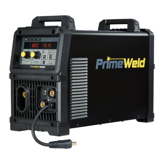
- Page 26 Fault indicator VRD indicator Right Multifunctional Data Display Left Multifunctional Data Display 2T/4T Selector Wire feed/ Current Adjustment Knob MIG/LIFT TIG /STICK Selector Advanced Features Selector Volts/Inductance Adjustment Knob MIG Gun/Spool Wire Feed Gun Cable Socket Control Socket Negative Output Terminal Positive Output Terminal...
-
Page 27: Mig Mode
VRD Indicator A VRD (voltage reduction device) is designed to reduce electric shock hazards present on the output of welding power source when operating in STICK mode. Note that the presence of VRD should not be used as a substitute for the use of appropriate safety practices as indicated in section one of this manual. - Page 28 Right Multifunctional Data Display MIG Mode This digital meter is used to display the pre-set (preview) Voltage in MIG mode and actual welding voltage of the power source when welding. At times of non-welding, the digital meter will display a pre-set (preview) value of Voltage. This value can be adjusted by varying the Right Knob.
- Page 29 Wire feed/Current Adjustment Knob The Wire feed/current adjusting knob adjusts the amount of welding current delivered by the power source. In STICK and LIFT TIG modes, the amperage control knob directly adjusts the power inverter to deliver the desired level of output current. In MIG mode, the amperage knob adjusts the speed of the wire feed motor (which in turn adjusts the output current by varying the amount of MIG wire delivered to the welding arc).
- Page 30 See chart1. STICK STICK STICK STICK (See Chart 2) Chart 2: The preset current under STICK mode Current Knob Left...
- Page 31 selector (Chart 3, Chart 4, Chart 5, Chart 6, Chart 7 and Chart 8) Chart 3 Chart 4 Chart 5 Chart 6 Chart 7 Chart 8...
- Page 32 (Chart 9 and Chart 10) Chart 9 Chart 10 VRD Function Setting: When machine is under STICK mode, press advanced features selector for 3 seconds to enter into menu mode, press advanced features selector to choose VRD function, rotate volts knob to turn on or off VRD function.(See Chart 11 and Chart 12) Chart 11 Chart 12...
- Page 33 STICK Chart 13). Chart 13 Left Chart 14 Chart 14...
- Page 34 STICK Chart 15) Chart 15...
- Page 35 Chart 16_1 Chart 16_2 Chart 16_1 Chart 16_2 Choose the Spool Gun / MIG Gun switch to Spool Gun, when machine is under MIG mode, long press advanced feature selector for 3 seconds to enter into menu mode, press advanced feature selector to choose Process function, rotate volts knob to choose ALUM.
- Page 36 Chart 20 Chart 19_1 Chart 19_2 Chart 19 Chart 20_1 Chart 20_2 Chart 20...
-
Page 37: Advanced Features Details
Advanced Features Details Select the weld process you wish to view Advanced Features for. Then long press the Advanced Features button for 3S to enter or exit from the Advanced Features programming function of the welder, then press and release the Advanced Features button to move forward through the list. -
Page 38: Right Display
MIG/MAG/FLUX Mode Advanced Features Menu map Left Display Right Display Advanced Menu-MIG Advanced Menu-MIG Mode Options or Range PROC / ESS C25/C100/FLUX/ALUX WIRE / DIAM 0.024/0.030/0.035/0.045 PRE- / FLOW 0.0-2.0 S POST / FLOW 0.0-10.0 S Run / IN 30-150% BURN / BACK 0.00-1.00 S WIRE / SHRP... - Page 39 Right Left Display Limits Comments Display Function (Factory Default Values) Burn Back BURN/BACK 0.10 0.00-1.00S The time difference between turning the wire feed OFF and the voltage is turned OFF. Wire Sharp WIRE/SHRP ON-OFF Wire Sharp adds a burst of current at the end of a weld to remove the ball at the end of the wire.
- Page 40 STICK Mode Advanced Features Menu map Left Display Right Display Advanced Menu-STICK Advanced Menu-STICK Mode Options or Range HOT / STRT ON OFF HS / TIME 0.0-2.0 S HS / AMPS 0-200% ARC- / FRCE OFF-200% ON OFF FACT / DFLT NO YES 0.0-9999.9 Press Advanced Button for 3s...
- Page 41 Chart 21 Chart 21 Chart 22 Chart 22 Chart 23 Chart 24 Chart 23 Chart 24...
- Page 42 Double Feed Rollers...
- Page 44 Err-01.
- Page 47 240V to 120V...
- Page 49 Err-01...
- Page 60 240V to 120V...
- Page 62 STICK STICK STICK STICK...
- Page 66 60 100 100 160 160 200 200 300...
- Page 73 Back Plastic Cover Torch Copper Connetor Kit Right Panel Wire Feeder Handle Reactor Panel Protective Cover Wire Feeder Bracket Main Board Support MIG/Spool Switch Front Panel Baseboard Digital Panel Spool Holder Knob Main Control Board Front Panel Hinge Insulated Seat for Control Socket Door Panel 4 pin Control Socket Latch...
Need help?
Do you have a question about the MIG285 and is the answer not in the manual?
Questions and answers