Advertisement
-
1
SAFETY
- 1.1 WARNING
- 1.2 CAUTION
- 1.3 Maintenance
- 1.4 Trouble shooting
- 1.5 Air plasma cutting technology
- 1.6 How the unit works
- 1.7 Operation
- 1.8 What kinds of materials can the plasma cut
- 1.9 How Does Plasma Cutting Compare to Oxy-fuel (gas) cutting
- 1.10 What are the limitations to Plasma Cutting and Where is Oxyfuel preferred?
- 1.11 Plasma Introduction
- 2 PARAMETER
- 3 LAYOUT
-
4
OPERATION
- 4.1 Start Cutting
- 4.2 Hand Torch cutting technique
- 4.3 Piercing
- 4.4 How to use air regulator
- 4.5 Machine Dimensions
- 4.6 Amperage
- 4.7 Speed
- 4.8 Direction
- 4.9 Torch tip height & position
- 4.10 Tip size and condition
- 4.11 Electrode condition
- 4.12 Air pressure and volume
- 4.13 Air Quality
- 4.14 Technique Tips
- 4.15 Torch Connector cover
- 5 TROUBLE SHOOTTING
- 6 ACCESSORIES
- 7 Documents / Resources
SAFETY
WARNING
Welding and cutting is dangerous to the operator، people in or near the working and surrounding areas, if the equipment is not operated correctly. Therefore the performance of welding/cutting must only be under the strict and comprehensive observance of all relevant safety regulations.
| Symbol | Descripiton |
 | Electric Shock: Maybe fetal
|
 | Smoke and gas generated while welding or cutting: Harmful to health of people
|
 | Fire Hazard
|
 | ARC light-emission: Harmful to the eyes & skin of people
|
 | CYLINDER may explode if damaged.
|
 | Engine fan can hurt the hands
|
 | ELECTRIC SHOCK can kill.
|
CAUTION
- Working Environment
- The environment in which this welding equipment is installed must be free of grinding dust. corrosive chemicals, flammable gas or materials etc, and at no more than maximum of 80% humidity.
- When using the machine outdoors protect the machine from direct sun light. rain water and snow etc: the temperature of working environment should be maintained within -14'F to + 104°F.
- Keep this equipment distant from the wall.
- Ensure the working environment is well ventilated.
- Safety Tips.
- Ventilation
This equipment is small-sized, compact in structure, and of excellent performance in amperage output.
The fan is used to dissipate heat generated by this equipment during the welding operation.
![]()
Maintain good ventilation of the louvers of this equipment.
The minimum distance between this equipment and any other objects in or near the working area should be 1ft. Good ventilation is of critical importance for the normal performance and service life of this equipment. - Thermal Overload protection.
Should the machine be used to an excessive level. or in high temperature environment, poorly ventilated area or if the fan malfunctions the Thermal Overload Switch will be activated and the machine will cease to operate. Under this circumstance, leave the machine switched on to keep the built-in fan working to bring down the temperature inside the equipment. The machine will be ready for use again when the internal temperature reaches safe level. - Over-Voltage Supply
Regarding the power supply voltage range of the machine, please refer to ' Main parameter table.
This equipment is of automatic voltage compensation, which enables the maintaining of the voltage range within the given range. In case that the voltage of input power supply amperage exceeds the stipulated value. it is possible to cause damage to the components of this equipment. Please ensure your primary power supply is correct. ![shock hazard]() Do not come into contact with the output terminals while the machine is in operation. An electric shock may possibly occur.
Do not come into contact with the output terminals while the machine is in operation. An electric shock may possibly occur.
- Ventilation

 Do not come into contact with the output terminals while the machine is in operation. An electric shock may possibly occur.
Maintenance
Exposure to extremely dusty, damp, or corrosive air is damaging to the welding machine. In order to prevent any possible failure or fault of this welding equipment, clean the dust at regular intervals with clean and dry compressed air of required pressure.
Please note that: lack of maintenance can result in the cancellation of the guarantee: the guarantee of this welding equipment will be void if the machine has been modified. attempt to take apart the machine or open the factory-made sealing of the machine without the consent of an authorized representative of the manufacturer.
Trouble shooting

Only qualified technicians are authorized to undertake the repair of this Plasma cutter equipment. For your safety and to avoid Electrical Shock. please observe all safety notes and precautions detailed in this manual.
Note:
- Our equipment as described in this manual conforms to all applicable rules and regulations of the 'Low Voltage Directive' (European Council Directive 73/23/EEC) as set out and amended by Council Directive 93/68/EEC) and to the National legislation for the enforcement of this Directive.
- Our equipment as described in this manual conforms to all applicable rules and regulations of the European Council Directive 89/336/EEC. (EMC Directive) and to the National legislation for he enforcement of this Directive.
Air plasma cutting technology
Plasma cutters work by passing an electric arc through a air/gas that is passing through a constricted opening. The gas can be air, nitrogen, argon, oxygen. etc. The electric arc elevates the temperature of the gas to the point that it enters a 4th state of matter. We all are familiar with the first three: i.e.,Solid, liquid, and gas. Scientists call this additional state plasma. As the metal being cut is part of the cireuit, the electrical conductivity of the plasma causes the arc to transfer to the work. The restricted opening (nozzle) the gas passes through causes it to squeeze by at a high speed, like air passing through a venturi in a carburettor.
This high speed gas cuts through the molten metal.
Plasma cutting was invented as the result of trying to develop a better welding process. Many improvements then led to making this technology what it is today. Plasma cutters provide the best combination of accuracy, speed, and afford ability for producing a variety of flat metal shapes. They can cut much finer, and faster than oxy-acetylene torches.
How the unit works
Basic plasma cutters use electricity to superheat air into plasma (the 4th state of matter), which is then blown through the metal to be cut. Plasma cutters require a compressed air supply and AC power to operate.
Operation

- When the trigger is squeezed, DC current flows through the torch lead into the nozzle.
- Next, compressed air flows through the torch head, through the air diffuser that spirals the air flow around the electrode and through the hole of the cutting nozzle.
- A fixed gap is established between the electrode and the nozzle. (The power supply increases voltage in order to maintain a constant current through the joint.) Electrons arc across the gap. ionizing and super heating the air creating a plasma stream.
- Finally, the regulated DC current is switched so that it no longer flows to the nozzle but instead flows from the electrode to the work piece. Current and airflow continue until cutting is stopped.
Notes:
The nozzle and electrode require periodic replacement. The electrode has an insert of tough high conductive material such as hafnium and cerium. This insert erodes with use, also the nozzle orifice will erode with use.
Quality of the air used is paramount to longer life of electrodes and nozzles, in short clean dry air gives longer parts life, the cleaner and dryer the better. We recommend use of a Plasma Air Filter.
What kinds of materials can the plasma cut
Virtually any metal can be plasma cut including steel, stainless steel, aluminium, brass, copper, etc. Any thickness from 30 gauge through 13116" can be cut, depending on the power of the plasma cutter used.
How Does Plasma Cutting Compare to Oxy-fuel (gas) cutting
Plasma cutting can be performed on any type of conductive metal - mild steel, aluminium and stainless are some examples. With mild steel, operators will experience faster, thicker cuts than with alloys. Oxy-fuel cuts by burning, or oxidizing the metal it is severing. It is therefore limited to steel and other ferrous metals which support the oxidizing process. Metals like aluminium and stainless steel form an oxide that inhibits further oxidization, making conventional oxy-fuel cutting impossible. Plasma cutting however does not rely on oxidation to work and thus it can cut aluminium, stainless and any other conductive material. While different gasses can be used for plasma cutting, most people today use compressed air for the plasma gas. In most shops, compressed air is readily available, and thus plasma does not require fuel gas and compressed oxygen for operation. Plasma cutting is typically easier for the novice to master, and on thinner materials, plasma cutting is much faster than oxy-fuel cutting. However, for heavy sections of steel (1" and greater), oxy-fuel is still preferred since oxy-fuel is typically faster and, for heavier plate applications high powered plasma machines are required for plasma cutting applications.
What are the limitations to Plasma Cutting and Where is Oxyfuel preferred?
The plasma cutting machines are typically more expensive than oxy/acetylene. Also. oxy/acetylene does not require access to electrical power or compressed air which may make it a more convenient method for some users. Oxyfuel can generally cut thicker sections (>63164 inch) of steel more quickly than plasma.
Plasma Introduction
The plasma Cutting process involves creating and electrical channel of super¬heated. electrically ionized gas i.e. plasma from the plasma cutter itself, through the work piece to be cut, thus forming a completed electric circuit back to the plasma cutter via a grounding clamp. This is accomplished by a compressed gas (Oxygen, air, inert and others depending on material being cut ) which is blown through a focused nozzle at high speed toward the work piece. An electrical arc is the formed within the gas. between an electrode near or integrated into the gas nozzle and the work piece itself. The electrical arc ionizes some of gas. thereby creating and electrically conductive channel of plasma. As electricity from the cutter torch travels down this plasma it delivers sufficient heat to melt through the work piece. At the same time, much of the high velocity plasma and compressed gas blow the hot molten metal away. thereby separating i.e. cutting through the work piece.
NOTE: This machine is designed to use only compressed air as gas.
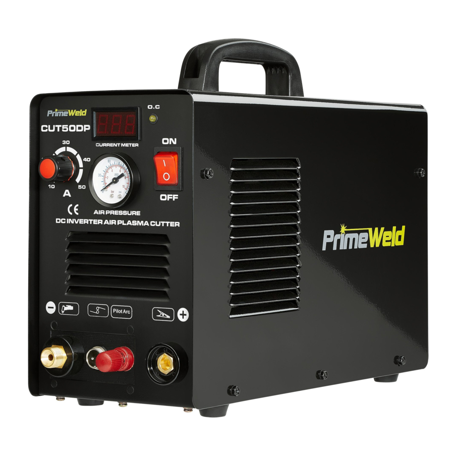
PARAMETER
Cut50dp with 50 Amps cutting current.
15mm Max Cutting thickness on Steel.
Inverter with Industrial Rated, Lightweight and Portable.

Amperage
- Latest IGBT Inverter Technology
- Safe torch connection
- High quality cutting torch with quality cable
- Industrial application
- Tolerant to variable power supply
- Quality Air regulator with preset air pressure
- Suitable to cut all electrically conductive materials
- Light weight and compact
- Strong metal housing
| Cut5ODP (110/220V) | ||
| Model | 220V | 110V |
| Power Supply / Phases (V-Ph) | 220V +/-15% | 110V +/-15% |
| Duty Cycle @ 78°F ( 25 C) | 60%@ 50Amps | 60%@ 40Amps |
| Rated Power (KVA) | 5.90 | 4.40 |
| Input Current Range (A) | 35-40 | 40-45 |
| Output Current Range (A) | 20-50 Amps | 20-40 Amps |
| Rated Output Voltage (V) | 100 | 96 |
| No-Load Voltage (Open Circuit(V)) | 260 | 260 |
| Efficiency (%) | 60 | 60 |
| Insulation Class | F | F |
| Protection Class | IP21S | IP21S |
| Plasma Arc Starting | HF Touch | HF Touch |
| Air Flow Pressure Range (PSI) | 40 - 65 psi | 40 - 65 psi |
| Air Flow Rate (CFM) | 5 L/min | 5 L/min |
| Clean Cutting Thickness (mm) | 12mm | 12mm |
| Cutting Thickness Severance (mm) | 16mm065psi | 12mm065psi |
| Cutting speed 10mm | 200mm/min(065 psi) | 150mm/min(065 psi) |
| Machine Dimenswns (inch) | 13 7 x 5 6" x 9 2" | 13 7 x 5 6" x 9 2" |
| Shipping Weight (kgs) | 8.9kgs | 8.9kgs |
Cutting Thickness chart
Need to adjust the current and air pressure properly under metal thickness to get best cutting surface
| 1 | Cut50dp -220V | 20Amps | 30Amps | 40Amps | 50Amps |
| Thickness (mm) | 5mm | 6mm | 10mm | 12mm | |
| Air Pressure (psi) | 40-50psi | 40-50psi | 50-60psi | 60-70psi | |
| 2 | Cut50dp -110V | 20Amps | 30Amps | 40Amps | |
| Thickness (mm) | 5mm | 6mm | 10mm | ||
| Air Pressure (psi) | 40-50psi | 40-50psi | 50-60psi |
SPECIFICATIONS
GENERAL DESCRIPTION
This unit is designed for light cutting project and weights only 11 kgs include accessories. This powerful unit is good enough to cut 12mm (75PSI air pressure) to 16mm severance thickness, making it an good idea for cost conscious DIY hobbyists.
- 50Amps inverter plasma cutter
- 120/220V automatic dual voltage and high frequency 50/60 Hz
- Suitable for stainless steel. Alloy steel, Mild steel. Copper and Aluminum, etc.

LAYOUT
How to install machine


Connection

Back Connection

Explosive View of Machine

OPERATION
Start Cutting

Hold the torch vertical at the odge Of he work piece

Pull the Trigger to start the arc, the cutting arc will initial when the Torch tip is close enough to the work Piece. Start Cutting on the edge until the Arc has cut completely through.

Then. Proceed with the cut.
Hand Torch cutting technique

When cutting make sure that sparks are exiting from the bottom of the work piece.

If sparks are spraying up from the work Piece, you are moving the torch too fast, or you don't have enough amps sel.

Hold the torch vertical and watch thearc as it cuts along the line.
Piercing

Hold the torch at an angle to the work piece, pull the trigger to start the arc and slowly rotate it to an upright position.

When sparks are exiting from the bottom of the work piece, the arc has pierced through the material

When the pierce is complete, proceed with cutting
How to use air regulator

Machine Dimensions

Amperage
Standard rule of thumb is the thicker the material the more amperage required. On thick material, set the machine to full output and vary your travel speed. On thinner material, you need to turn down the amperage and change to a lower-amperage tip to maintain a narrow kerf. The kerf is the width of the cut material that is removed during cutting.
Speed
Amperage and speed are critical to producing a good quality cut. The faster you move (especially on aluminium), the cleaner your cut will be. To determine if you're going too fast or too slow, visually follow the arc that is coming from the bottom of the cut. The arc should exit the material at a slight angle away from the direction of travel. If it's going straight down. that means you're going too slow. and you'll have an unnecessary buildup of dross or slag. If you go too fast, it will start spraying back onto the surface of the material without cutting all the way through. Because the arc trails at an angle, at the end of a cut, slow your cutting speed and angle the torch in to cut through the last bit of metal.
Direction
It is easier to pull the torch towards you than push it. The plasma stream swirls as it exits the tip, biting one side and finishing off on the other leaving a bevelled edge and a straight edge. The bevel cut effect is more noticeable on thicker material and needs to taken into consideration before starting your cut as you want the straight side of the eut to be on the finished piece you keep.
Torch tip height & position
The distance and postion of the plasma torch cutting tip has an affect on the quality of the cut and the extent of the bevel of the cut. The easiest way to reduce bevel is by cutting at the proper speed and height for the material and amperage that is being cut.

Correct torch height and Square to the material Minimum bevel & equal bevel Longest consumable life

Torch Angled to the material unequal bevel, one side may be excessively beveled.

Torch height too high excessive bevel; plasma Stream may not cut all the way through the material

Torch height too low Reverse bevel. Tip may contact the work piece and short out or damage the tip.
Tip size and condition
The tip orifices focus the plasma stream to the work piece. II is important to use the correct size tip for the amperage being used.for example a tip with a 3/64" orifice is good for 0-40 amps whereas a 1/16" orifice is better for 40-80 amps. The low-amp tip has a smaller orifice which maintains a narrow plasma stream at lower settings for use on thin-gauge material. Using a 25 amp tip at an 60 amp setting will blow out and distort the tip orifice and require replacement.
Conversely. using an 80-amp tip on the lower settings will not allow you to focus the plasma stream as well and creates a wide kerf. The condi Lion of the tip orifice is critical to the quality of the cut result. a worn or damaged tip orifice will produce a distorted plasma stream resulting in a poor cut quality.
Electrode condition
A fixed gap is established between the electrode and the inside of the cutting tip. Electrons arc across the gap, ionizing and super heating the air creating the plasma stream. The electrode contains an insert in the end made of a highly conductive material called hafnium. This insert erodes with use and develops a pit in the end of the electrode, when the pit becomes too much poor quality cuts will result and necessitate replacement of the electrode.
Air pressure and volume
Air pressure, flow rate and air quality are critical to quality plasma cutting and consumable life span. The required air pressure and volume can vary from model to model and the manufacturer will provide the specs. The primeweld cut50 air pressure is pre-set at 4.5 psi and requires a flow rate of 6.0 CF/M. The volume capacity of your compressor is important. if you have a small compressor with exactly the same l/min rating as the plasma, then the compressor will run continuously when you are plasma cutting. a compressor with a l/min rating slightly higher than the plasma would be more adequate. If you are doing a lot of cutting, cutting thick plate (same air consumption but slower cut speeds = longer cut time) then choose a compressor at 1.5 to 2 times the plasma system requirement.
Air Quality
Good air quality is essential to quality plasma cutting and consumable life span. Compressors take in air at atmospheric pressure and increase the pressure and store it in a tank. Humidity in the air is condensed in the tank and in the airlines producing water, more so in humid environments. Moisture that forms in air lines has a tendency to condense into larger drops when the air pressure decreases as it is entering the plasma torch. When these droplets enter into the high temperatures (as much as 19832°f) in the plenum of the torch, they immediately break down into oxygen and hydrogen, which alters the normal chemical content of air in the torch. These elements will then dramatically change the plasma arc which causes the torch consumable parts to wear very quickly, alters the shape of the nozzle orifice, dramatically affecting cut quality in terms of edge squareness, dross formation, and edge smoothness. Minimising the moisture in the air supply is absolutely critical to quality plasma cuts and longevity of consumable parts. As a minimum be sure to drain the receiver (tank) on the air compressor at least daily. Most air plasma systems from reputable manufacturers have an on board particulate filter and or a coalescing filter with an auto drain that will remove some moisture from the air supply. For home workshop and light industrial users the on board air filter is adequate. Most situations however will require additional filtration to prevent moisture from affecting the quality of the plasma cutter and in most cases it is recommended to install a sub micronic particulate filter that is designed to trap water through absorption. This style of filter has a replaceable filter cartridge that absorbs water and must be changed after it is near saturation, it should be installed close as possible to the air intake of the plasma cutter.
Technique Tips
- It is easier to pull the torch through the cut than to push it.
- To cut thin material reduce the amperage until you get the best quality cut.
- Use the correct size tip orifice for the amperage being used.
- For Straight cuts use a straight edge or cutting buggy as a guide. For circles, use a template or circle cutting attachment.
- Check that the front end consumable parts of the plasma cutting torch are in good condition.
Torch Connector cover

TROUBLE SHOOTTING
| Problems | Analysis | Solution |
|
|
|
|
|
|
|
|
|
|
|
|
|
|
|
|
|
|
|
|
|
|
|
|
|
|
|
|
|
|
|
|
|
|
|
|
ACCESSORIES

Connect your plasma cutting torch and ground cable to the front panel of the machine

Torch Consumables Model: AG-60P
Need Help
Please Call
856-537-4368
info@primeweld.com
www.primeweld.com
Documents / Resources
References

Download manual
Here you can download full pdf version of manual, it may contain additional safety instructions, warranty information, FCC rules, etc.
Advertisement


Need help?
Do you have a question about the CUT50DP and is the answer not in the manual?
Questions and answers