Advertisement
-
1
SAFETY
- 1.1 WARNING
- 1.2 CAUTION
- 1.3 Maintenance
- 1.4 Trouble shooting
- 1.5 Air plasma cutting technology
- 1.6 How the unit works
- 1.7 Operation
- 1.8 What kinds of materials can the plasma cut
- 1.9 How Does Plasma Cutting Compare to Oxy-fuel (gas) cutting
- 1.10 What are the limitations to Plasma Cutting and Where is Oxyfuel preferred?
- 2 INPUT/OUTPUT SPECIFICATIONS
- 3 LAYOUT
-
4
OPERATION
- 4.1 Amperage
- 4.2 Speed
- 4.3 Direction
- 4.4 Torch tip height & position
- 4.5 Tip size and condition
- 4.6 Electrode condition
- 4.7 Air pressure and volume
- 4.8 TUNGSTEN PREPARATION
- 4.9 HIGH FREQUENCY START TIG OPERATION
- 4.10 STICK OPERATION
- 4.11 FRONT PANEL FEATURES AND CONTROLS
- 4.12 Air quality
- 4.13 Technique Tips
- 4.14 Safety Trigger Operation
- 4.15 Power cable connection
- 5 ACCESSORIES
- 6 TROUBLE SHOOTTING
- 7 Documents / Resources
SAFETY
WARNING
Welding and cutting is dangerous to the operator, people in or near the working and surrounding areas, if the equipment is not operated correctly. Therefore the performance of welding/cutting must only be under the strict and comprehensive observance of all relevant safety regulations.
| Symbol | Description |
 | Electric Shock: Maybe fatal
|
 | Smoke and gas generated while welding or cutting: Harmful to health of people
|
 | Fire Hazard
|
 | ARC light-emission: Harmful to the eyes & skin of people
|
 | CYLINDER may explode if damaged.
|
 | Engine fan can hurt the hands
|
 | ELECTRIC SHOCK can kill.
|
CAUTION
- Working Environment.
- The environment in which this welding equipment is installed must be free of grinding dust, corrosive chemicals, flammable gas or materials etc, and at no more than maximum of 80% humidity.
- When using the machine outdoors protect the machine from direct sun light, rain water and snow etc; the temperature of working environment should be maintained within -14°F to +104°F.
- Keep this equipment distant from the wall.
- Ensure the working environment is well ventilated.
- Safety Tips.
- Ventilation
This equipment is small-sized, compact in structure, and of excellent performance in amperage output. The fan is used to dissipate heat generated by this equipment during the welding operation. Important: Maintain good ventilation of the louvers of this equipment. The minimum distance betweenthis equipment and any other objects in or near the working area should be 1ft. Good ventilation is of critical importance for the normal performance and service life of this equipment. - Thermal Overload protection.
Should the machine be used to an excessive level, or in high temperature environment, poorly ventilated area or if the fan malfunctions the Thermal Overload Switch will be activated and the machine will cease to operate. Under this circumstance, leave the machine switched on to keep the built-in fan working to bring down the temperature inside the equipment. The machine will be ready for use again when the internal temperature reaches safe level. - Over-Voltage Supply
Regarding the power supply voltage range of the machine, please refer to "Main parameter" table. This equipment is of automatic voltage compensation, which enables the maintaining of the voltage range within the given range. In case that the voltage of input power supply amperage exceeds the stipulated value, it is possible to cause damage to the components of this equipment. Please ensure your primary power supply is correct. ![shock hazard]() Do not come into contact with the output terminals while the machine is in operation. An electric shock may possibly occur.
Do not come into contact with the output terminals while the machine is in operation. An electric shock may possibly occur.
- Ventilation
 Do not come into contact with the output terminals while the machine is in operation. An electric shock may possibly occur.
Maintenance
Exposure to extremely dusty, damp, or corrosive air is damaging to the welding machine. In order to prevent any possible failure or fault of this welding equipment, clean the dust at regular intervals with clean and dry compressed air of required pressure.
Please note that: lack of maintenance can result in the cancellation of the guarantee; the guarantee of this welding equipment will be void if the machine has been modified, attempt to take apart the machine or open the factory-made sealing of the machine without the consent of an authorized representative of the manufacturer.
Trouble shooting

Only qualified technicians are authorized to undertake the repair of this Plasma cutter equipment. For your safety and to avoid Electrical Shock, please observe all safety notes and precautions detailed in this manual.
Note:
- Our equipment as described in this manual conforms to all applicable rules and regulations of the 'Low Voltage Directive' (European Council Directive 73/23/EEC) as set out and amended by Council Directive 93/68/EEC) and to the National legislation for the enforcement of this Directive.
- Our equipment as described in this manual conforms to all applicable rules and regulations of the European Council Directive 89/336/EEC, (EMC Directive) and to the National legislation for he enforcement of this Directive.
Air plasma cutting technology
Plasma cutters work by passing an electric arc through a gas that is passing through a constricted opening. The gas can be air, nitrogen, argon, oxygen. etc.
The electric arc elevates the temperature of the gas to the point that it enters a 4th state of matter. We all are familiar with the first three: i.e.,Solid, liquid, and gas. Scientists call this additional state plasma. As the metal being cut is part of the circuit, the electrical conductivity of the plasma causes the arc to transfer to the work. The restricted opening (nozzle) the gas passes through causes it to squeeze by at a high speed, like air passing through a venturi in a carburettor. This high speed gas cuts through the molten metal.
Plasma cutting was invented as the result of trying to develop a better welding process. Many improvements then led to making this technology what it is today. Plasma cutters provide the best combination of accuracy, speed, and afford ability for producing a variety of flat metal shapes. They can cut much finer, and faster than oxy-acetylene torches.
How the unit works
Basic plasma cutters use electricity to superheat air into plasma (the 4th state of matter), which is then blown through the metal to be cut. Plasma cutters require a compressed air supply and AC power to operate.
Operation

- When the trigger is squeezed, DC current flows through the torch lead into the nozzle.
- Next, compressed air flows through the torch head, through the air diffuser that spirals the air flow around the electrode and through the hole of the cutting nozzle.
- A fixed gap is established between the electrode and the nozzle. (The power supply increases voltage in order to maintain a constant current through the joint.) Electrons arc across the gap, ionizing and super heating the air creating a plasma stream.
- Finally, the regulated DC current is switched so that it no longer flows to the nozzle but instead flows from the electrode to the work piece. Current and airflow continue until cutting is stopped.
Notes:
The nozzle and electrode require periodic replacement. The electrode has an insert of tough high conductive material such as hafnium and cerium. This insert erodes with use, also the nozzle orifice will erode with use.
Quality of the air used is paramount to longer life of electrodes and nozzles, in short clean dry air gives longer parts life, the cleaner and dryer the better. We recommend use of a Plasma Air Filter.
What kinds of materials can the plasma cut
Virtually any metal can be plasma cut including steel, stainless steel, aluminium, brass, copper, etc. Any thickness from 30 gauge through 13/16" can be cut, depending on the power of the plasma cutter used.
How Does Plasma Cutting Compare to Oxy-fuel (gas) cutting
Plasma cutting can be performed on any type of conductive metal-mild steel, aluminium and stainless are some examples. With mild steel, operators will experience faster, thicker cuts than with alloys. Oxy-fuel cuts by burning, or oxidizing the metal it is severing. It is therefore limited to steel and other ferrous metals which support the oxidizing process. Metals like aluminium and stainless steel form an oxide that inhibits further oxidization, making conventional oxy-fuel cutting impossible. Plasma cutting however does not rely on oxidation to work and thus it can cut aluminium, stainless and any other conductive material. While different gasses can be used for plasma cutting, most people today use compressed air for the plasma gas. In most shops, compressed air is readily available, and thus plasma does not require fuel gas and compressed oxygen for operation. Plasma cutting is typically easier for the novice to master, and on thinner materials, plasma cutting is much faster than oxy-fuel cutting. However, for heavy sections of steel (1" and greater), oxy-fuel is still preferred since oxy-fuel is typically faster and, for heavier plate applications high powered plasma machines are required for plasma cutting applications
What are the limitations to Plasma Cutting and Where is Oxyfuel preferred?
The plasma cutting machines are typically more expensive than oxy/acetylene. Also, oxy/acetylene does not require access to electrical power or compressed air which may make it a more convenient method for some users. Oxyfuel can generally cut thicker sections (>63/64 inch) of steel more quickly than plasma.
INPUT/OUTPUT SPECIFICATIONS
| IGBT Inverter Type: | IGBT |
| Voltage/phase: | Dual Voltage 120/240 1 Phase |
| TIG output type: | DC only |
| TIG Start Type: | High Frequency Only |
| Pulse: | No |
| Plasma Cutter Arc Start Type: | High Frequency |
| PilotArc: | No |
| OK-to-Cut Indicator/Low Air pressure safety: | No |
| OCV: |
|
| Max Inrush ( I1MAX ) Amps: |
|
| Maximum Rated (I1EFF ) Input Amps: |
|
| TIG Output Amps/Volts @ Rated Duty Cycle: | 120V:
240V:
|
| Stick Output Amps/Volts @ Rated Duty Cycle: | F120V:
240V:
|
| Plasma Output Amps/Volts @ Rated Duty Cycle: | 120V:
240V:
|
| TIG DC Amp/Volt Range: |
|
| Stick Amp/Volt Range: |
|
| Plasma Amp/Volt Range: |
|
| Preflow time: | Fixed |
| Post Flow Time: | Fixed |
| OverCurrent Protection: | Yes |
| Duty Cycle Protection: | Yes |
| Air Pressure OK Safety Indicator: | No |
| Stick Arc Force Control: | Auto-Adaptive |
| Torch Type: | AG-60 High Frequency |
| Recommended Cutting Air Pressure: | 55-60 psi |
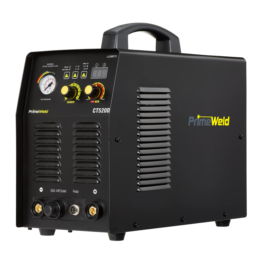
LAYOUT
Front & rear panel layout

| 1 |  | Overheating indicator, It illuminates when the working temperature of the IGBT is overly high. Meanwhile, The machine stop working. |
| 2 |  | It is current indicator, Lighting when machine power on |
| 3 | LED Current Display. | |
| 4 | Amperage Control Knob. | |
| 5 | Time adjument for post air | |
| 6 | Air Pressure Gauge. Suggest Air Range: 45-70PSI | |
| 7 |  | Machine indicator, Current knob can use in this selection, can not use pedal. |
 | Pedal: current knob on machine can not be used in this selection, Can use the pedal adjust the current | |
| 8 |  | 4T is selected press and release trigger Arc starts, press and release trigger Arc stops. |
 | 2T is selected press trigger Arc starts, release trigger Arc stops. | |
| 9 |  | TIG function please select it before using machine |
 | Cutting function please select it before using machine | |
 | Stick function please select it before using machine | |
| 10 | Stick connector | |
| 11 | TIG and Cutting torch connector | |
| 12 | Switch connector for TIG and Cutting torch | |
| 13 | Earth clamp connector | |
| 14 | Air regulator | |
| 15 | Power switch | |
| 16 | Quick air connector | |
| 17 | Power cable Input Voltage 110/220v, Voltage Automatic Identification, no need hand switch | |
| 18 | Argon Gas in | |
| 19 | Air in | |
| 20 | To Air Meter | |
Set up procedure for plasma cutting machine
- Connect the AG60/AG60P Plasma Torch to the machine. Insert the torch connection into the torch. Connection receptacle at the front of the machine and screw up hand tight. Caution: Be careful not to bend the pins located inside the torch connector.
- Connect the earth lead to the output terminal of the machine and tighten.
- Connect the air supply to the air connection located at the rear of the machine. Turn on the air supply.
- Connect the machine to the correct power supply and switch on the machine using the on/off switch located at the rear of the machine.
- Select 2T / 4T operation
Operating procedure using the 2T / 4T Function with AG60/AG60P torch. Set torch operation 2T / 4T.- When 2T operation is selected press trigger Arc starts, release trigger Arc stops.
- When 4T operation is selected press and release trigger Arc starts, press and release trigger Arc stops.
- Set amperage dial.
How to begin use this machine
Before use this machine, you need to read the blow information carefully, Put the accessories ready before operate this unit

CONNECTION


 Before use pedal, please switch function "Machine"to "Pedal " please connect torch and ground clamp well, leave torch switch free(do not plug it to TIG torch switch port), Connect foot pedal to panel of machine.
5 PIN CONNECTOR FOR FOOT PEDAL

How to use air regulator

Air Pressure range: 40-70 PSI
Function & Install instruction
HOW TO USE MMA(Stick)
Select MMA mode, Stick holder connect to left socket, same time connect earth clamp to the right socket.

HOW TO USE CUT
Before start use cutting function, need to select cut mode, then connect torch and switch and pilot arc wire also earth clamp to panel of machine. start cutting after all connectting.

HOW TO USE TIG
Select TIG mode, connect torch, switch and earth clamp to panel of machine. start TIG welding after finish all connectting.


- For connect stick holder
- GAS/AIR OUTLET
- PEAL/ Torch switch
- For connect earth clamp
How to connect wire for TIG welding

- Connect the TIG torch & switch to panel of machine
- connect the plug of earth clamp to the machine socket.
How to connect wire for cutting function

- connect the plasma torch & switch to socket of panel, ( also need to connect the pilot arc wire if machine with pilot arc function )
- connect the earth clamp to socket on panel of machine
How to connect wire for stick welding

- connect the plug on wire of stick holder to panel of machine ( there is symbol mark on machine )
- connect the plug on wire of earth clamp to panel of machine.
Cutting Thickness Chart
Need to adjust the current and air pressure properly under metal thickness to get best cutting surface
| 1 | CT520 (220V) | 20Amps | 30Amps | 40Amps | 50Amps |
| Thickness (mm) | 4mm | 6mm | 10mm | 14mm | |
| Air Pressure (psi) | 40psi | 50psi | 60psi | 70psi | |
| Tip size | φ0.8-φ0.9 | φ0.8-φ0.9 | φ0.9-φ1.0 | φ0.9-φ1.0 | |
| 2 | CT520 (110V) | 25Amps | 35Amps | ||
| Thickness (mm) | 4mm | 6mm | |||
| Air Pressure (psi) | 40psi | 50psi | |||
| Tip size | φ0.8-φ0.9 | φ0.8-φ0.9 | |||
Accessories
Following accessories come with machine


- machine x 1
- plasma cutting torch x 1
- earth clamp with cable x 1
- air hose x 1
- cutting torch tip x 2
- cutting torch electrode x 2
- Air regulator x 1
- Power plug wire adaptor x 1
- TIG torch * 1
- Arc holder with cable *1
OPERATION
- place and hold the torch vertical At the edge of the plate.
![]()
- Pull the trigger to energise the pilot arc. The cutting arc will start when the nozzle is moved closer to the edge of the work piece. When the cutting arc has cut through the edge of the plate start moving evenly in the direction you wish to cut.
![]()
- Correct amperage and travel speed arc importand and relevant to material thickness and are correct when sparks are exiting from the work piece. if sparks are spraying up from the work piece there is insufficient amps selected or the travel speed is too fast.
![]()
- To finish the cutting release the torch switch. The air flow will continue for 20 seconds to cool the torch head.
![]()


Cut Quality
A clean cut depend on several factors:
- amperage
- travel speed
- tip height & position
- tip and electrode quality
- air pressure and quality
- technique
The best quality cut will be produced when all these variables are set correctly for the material thickness and type of material being cut.

Amperage
Standard rule of thumb is the thicker the material the more amperage required. On thick material, set the machine to full output and vary your travel speed. On thinner material, you need to turn down the amperage and change to a lower-amperage tip to maintain a narrow kerf. The kerf is the width of the cut material that is removed during cutting.
Speed
Amperage and speed are critical to producing a good quality cut. The faster you move (especially on aluminium), the cleaner your cut will be. To determine if you're going too fast or too slow, visually follow the arc that is coming from the bottom of the cut. The arc should exit the material at a slight angle away from the direction of travel. If it's going straight down, that means you're going too slow, and you'll have an unnecessary buildup of dross or slag. If you go too fast, it will start spraying back onto the surface of the material without cutting all the way through. Because the arc trails at an angle, at the end of a cut, slow your cutting speed and angle the torch in to cut through the last bit of metal.
Direction
It is easier to pull the torch towards you than push it. The plasma stream swirls as it exits the tip, biting one side and finishing off on the other leaving a bevelled edge and a straight edge. The bevel cut effect is more noticeable on thicker material and needs to taken into consideration before starting your cut as you want the straight side of the cut to be on the finished piece you keep.
Torch tip height & position
The distance and postion of the plasma torch cutting tip has an affect on the quality of the cut and the extent of the bevel of the cut. The easiest way to reduce bevel is by cutting at the proper speed and height for the material and amperage that is being cut.

Correct torch height and Square to the material Minimum bevel & equal bevel Longest consumable life

Torch angled to the material unequal bevel, one side may be excessively beveled.

Torch height too high excessive bevel, plasma Stream may not cut all the way through the material

Torch height too low Reverse bevel. Tip may contact the work piece and short out or damage the tip.
Tip size and condition
The tip orifices focus the plasma stream to the work piece. It is important to use the correct size tip for the amperage being used, for example a tip with a 3/64" orifice is good for 0-40 amps whereas a 1/16" orifice is better for 40-80 amps.
The low-amp tip has a smaller orifice which maintains a narrow plasma stream at lower settings for use on thin-gauge material. Using a 25 amp tip at an 60 amp setting will blow out and distort the tip orifice and require replacement. Conversely, using an 80-amp tip on the lower settings will not allow you to focus the plasma stream as well and creates a wide kerf. The condi tion of the tip orifice is critical to the quality of the cut result, a worn or damaged tip orifice will produce a distorted plasma stream resulting in a poor cut quality.
Electrode condition
A fixed gap is established between the electrode and the inside of the cutting tip.
Electrons arc across the gap, ionizing and super heating the air creating the plasma stream. The electrode contains an insert in the end made of a highly conductive material called hafnium. This insert erodes with use and develops a pit in the end of the electrode, when the pit becomes too much poor quality cuts will result and necessitate replacement of the electrode.
Air pressure and volume
Air pressure, flow rate and air quality are critical to quality plasma cutting and consumable life span. The required air pressure and volume can vary from model to model and the manufacturer will provide the specs. The air pressure is pre-set at 4.5 psi and requires a flow rate of 6.0 CF/M. The volume capacity of your compressor is important, if you have a small compressor with exactly the same l/min rating as the plasma, then the compressor will run continuously when you are plasma cutting, a compressor with a l/min rating slightly higher than the plasma would be more adequate. If you are doing a lot of cutting, cutting thick plate (same air consumption but slower cut speeds = longer cut time) then choose a compressor at 1.5 to 2 times the plasma system requirement.
TIP: For longer consumable life do not use the pilot arc unnecessarily. Rapid wear will occur if the pilot arc stays engaged more than 3 seconds at a time.
NOTE: When stepping down amps to cut thinner material, or using on 120V, you must change to smaller orifice nozzle for the best cutting results. Too large of an orifice diameter will result in arc instability and a rough cut. Lowering the air pressure below 50 psi to try to get the torch to cut will only result in a lazy, wandering arc or an arc that sputters on and off continuously.


Check consumables regularly for wear and change them out before they are completely worn. Allowing the consumables to wear until they quit working may damage related torch components, creating a more costly repair.
Helpful Hint: If difficulty is observed in starting the arc, it may be time to readjust the point gap setting found inside. The HF points tend to wear and get dirty over time. This is a normal maintenance item and not something for warranty consideration. Proper point gap adjustment is.035 "to.045". Before attempting to adjust the point gap, be sure to unplug the unit for 15 minutes before removing the rear plastic panel, and the steel case to access the points located near the front of the unit. Do not remove the front panel! Use a feeler gauge to adjust the points to the proper setting. Another possibility is that the air pressure is too low or too high. Worn/loose consumables may cause this as well.
Edge Starts are the best type of start if possible to promote consumable and torch life. This reduces blow back of molten material and allows a smooth gradual start of the cut.

- Line up the hole on the tip of the electrode on the edge of the cut. Hold torch perpendicular to the cut initially, about 1/16" off the metal.
- Once the arc starts, wait for the arc to penetrate all the way through the metal.
- As the torch penetrates its flame all the way through the metal, tilt the torch so there is a slight lead in the flame if metal is thin. If it is thick, keep holding torch in a nearly vertical position.
- Begin moving the torch in the direction of the cut. Maintain 1/16" standoff height.
- Move the torch fast enough so the sparks and flame trail from the bottom edge at an angle of no more than 30° and no less than 10° from perpendicular to the metal. Excess angle of sparks/flame indicate too fast of travel speed or practical cut capacity has been reached. Little or no angle indicates too slow of travel speed.
Piercing starts often result in rapid consumable wear and excess blow back of molten metal deposited onto torch and consumables. This should be done only as necessary.

- Tilt the torch in the direction of travel or toward the side of the metal to be discarded or wasted at a 40° to 60° angle. Slide the yellow safety lock and squeeze the trigger.
- Once the arc starts, wait for the arc to transfer from pilot arc to the cutting arc.
- As the torch penetrates it flame at an angle rotate the torch slowly to the vertical position, as the arc penetrates the metal. Tilt the torch from 0°-15° for thin metal cuts, or hold it nearly perpendicular for thicker metal cuts.
- Begin moving the torch in the direction of the cut. Maintain 1/16" standoff height.
- Move the torch fast enough so the sparks and flame trail from the bottom edge at an angle of no more than 30° and no less than 10° from perpendicular to the metal. Excess angle of sparks/flame indicate too fast of travel speed or practical cut capacity has been reached. Little or no angle indicates too slow of travel speed.
If you use a standoff guide with the torch, it must be adjusted or bent to provide no more than 1/8" standoff, less if possible. Long standoff heights reduce cut capacity and quality. It also promotes rapid consumable wear and can prevent the pilot arc from transferring.
When cutting an object, particularly a pattern shape, where the torch must pierce or re-fire in-line at an intersection of a cut, a lead-in cut should be employed. A lead-in is a cut that is made in the disposable part (also known as a drop) of the object to "lead" into the main part of the cut so that the destructive force of the arc is not directed into the desirable side of the cut itself. Also, all plasma cutters exhibit some angularity or bevel in the cut which is greater on one side than the other. Keep this in mind when cutting an object to size so that too much metal is not accidentally removed.


TUNGSTEN PREPARATION
 |
|
 | DO NOT GRIND TUNGSTEN PARALLEL TO WHEEL FACE OR AN UNSTABLE ARC WILL RESULT. |
 | Use a point for low amp use to help control arc. Create a slight truncation on the tip for higher amp use for best arc stability. Grind the tip so that it is 2.5-3 times longer than the tungsten is wide (Diameter). |
 | DO NOT BALL TUNGSTEN. AN ERRATIC ARC MAY RESULT. MAKESURE GRINDING MARKS RUNPARALLEL AND IN LINE WITH THETIP. CONCENTRIC MARKS WILLCAUSE AN ERRATIC ARC. |
Be sure to select the best Tungsten for your application. Low amp starts are difficult if too large of Tungsten is used. Use only lanthanated, ceriated or thoriated Tungsten. Do not use pure Tungsten (marked with green tip).
| GENERAL POLARITY RECOMMENDATIONS* *Follow manufacturer of stick electrode for complete polarity recommendations | ||||
| PROCESS | TORCH POLARITY | WORK POLARITY | ||
| TIG (GTAW) | - | + | ||
| STICK (SMAW) | + | - | ||
| TIG (GTAW) OPERATION GUIDE FOR STEEL (ALUMINUM)* *As a general rule, set amperage using 1 amp for every.001" of metal thickness for aluminum. Less is required for DC. | ||||
| METAL THICKNESS | WELDING AMPS (A) | TUNGSTEN DIA. | Ar FLOW RATE | |
| 1-3 mm/.040"-1/8" | 40-80 (60-125) | .040"-3/32" | 8-15 CFH | |
| 3-6 mm/ 1/8"-1/4" | 80-200 (125-200) | 3/32"-1/8" | 15-25 CFH | |
| 6-10 mm 1/4"-3/8" | 150-200 (200-250) | 1/8"-1/4" | 20+ CFH | |
| TUNGSTEN SELECTION GUIDE FOR AN INVERTER | ||||
| TYPE | PERCENT | COLOR | PROCESS | RECOMMENDATION |
| Pure | 100% Tungsten | Green | AC | NOT RECOMMENDED! Do not use in an inverter. |
| Thoriated (slightly radioactive) | 2% Thorium | Red | AC/DC | YES. Great for all purpose welding. Most economical. |
| Ceriated | 2% Ceria | Orange | AC/DC | YES. Good for low amp use. |
| Lanthanated | 1.5% Lanthanum | Gold | AC/DC | YES. Best alternative to 2% Thoriated. Tough performer. |
| Lanthanated | 2% Lanthanum | Blue | AC/DC | YES. Slight advantage over 1.5% Lanthanated. |
| Zirconiated | 1% Zirconia | Brown | AC | NOT RECOMMENDED! Do not use in an inverter. |
HIGH FREQUENCY START TIG OPERATION
- Position the point of the sharpened tungsten about 1/8" or less above the metal.
![]()
- Press the torch trigger or press the foot pedal to initiate the arc. The HF arc will be initiated. It may appear briefly as a blue spark.
![]()
- An arc should form almost immediately. If arc does not start, and the HF is creating a spark, then check the work clamp connectivity to the work piece. Grind a clean spot to attach the clamp if necessary. Connect the work clamp directly to the object being welded Move the tungsten closer to the work. Also check polarity if arc does not start or tungsten balls, or burns quickly. Repeat steps 1 and 2.
![]()
- Leave 1/8" or less gap between the tungsten tip and the metal and proceed with welding, leaving the torch inclined at a maximum 15° angle.


General TIG Arc Starting Steps
- Turn the unit on, allow time for power up cycle to complete its start up process.
- Select TIG mode with TIG /CUT/Stick selector button.
- Plug in the TIG Torch with either the torch switch or foot pedal connected. Then select panel mode or pedal mode with the selector button depending upon whether the foot pedal (pedal mode) or torch switch (panel mode) was chosen for use.
- Adjust to the desired Post Flow time by rotating the knob to increase/decrease. (Usually.5 to 1 second per 10 amps)
- Select maximum amps with amp control knob.
- Start arc as depicted above by either pressing and holding the torch switch or by stepping down slightly on the pedal.
- If you are using the panel mode, continue to hold the torch switch until you are ready to stop welding. Release the switch. The welding arc will then cease. If you are using the foot pedal raise your foot completely off the pedal and arc will stop automatically.
STICK OPERATION
- Turn on the power switch on the rear of the unit. Allow unit to cycle through its start up program.
- Select the Stick mode with the TIG/Cut/Stick selector switch.
- Make sure electrode holder is connected to the positive connector and the work clamp is connected to the negative connector. Remember, this is the opposite connection required for TIG and plasma.
- Select the desired amperage. Use the electrode diameter selection chart in this manual to determine the approximate range of amps suitable for the rod size selected. Consult the welding electrode manufacturer's recommendation for proper amperage range. Each manufacturer has specific recommendations for its electrodes. Ultimately Amperage is determined by the electrode thickness and the thickness of the metal.
- Strike the arc with either the tapping method or the match strike method. Beginners usually find that the match strike method yields best results. Professionals tend to gravitate toward the tapping method because of its placement accuracy which helps prevent arc striking outside of the weld zone.


Do not weld in the TIG mode with the stick electrode holder still attached.
FRONT PANEL FEATURES AND CONTROLS
| FEATURES | PARAMETERS | PURPOSE |
| N/A | Indicates actual amp output while welding. While adjusting or while not welding, the function of the display changes to display the selected amperage. |
| On/Off | The On indicator should always be lit while the unit is plugged in and the power switch is switched on. If the Overcurrent light is lit, turn the unit off and check for possible causes including undersized cables, poor connections and overheating cables. If the Duty cycle is lit, do not turn off the unit until it has had sufficient time to cool (10-15 minutes). Cycle the power switch to reset the machine only after the machine has had time to cool. The duty cycle and overcurrent warning lights should go off after cycling the power switch on the machine. If it does not, contact. |
| N/A | This switch determines which mode controls the unit, the torch switch (Panel) or the pedal. Using either one will determine how the unit reads and sets the maximum output of the machine. |
| N/A | This switch selects processes. Do not switch this switch while welding or cutting, Do not switch it with the wrong torch connected or immediate failure of the unit may result. Improper polarity can contribute to torch failure as well. Make sure all connections are installed properly before cutting or welding. |
| N/A | Controls amperage while welding or cutting by using the knob to preset maximum amperage. |
| 2-8 Seconds | Sets the post flow time of the shielding gas while welding in TIG mode. While in plasma (cut) mode, it sets the post flow time of the air. Time is an approximation only and can vary a little from the setting posted on the dial. The air or shielding gas may stop flowing before full maximum time is reached. Consider the maximum setting mark a reference guide only. |
| N/A | This connection is only used with the plasma cutting torch. The small ringed wire connects here. Unscrew the plastic thumb nut and attach the wire to the post. Reinstall the thumb nut over the wire with finger pressure only. Do not overtighten |
| DINSE 25 | Location of the negative terminal connection. Dinse-style. For Stick: Work Clamp Connection. For TIG: Torch Connection. For Plasma: Torch Connection. |
| 9mm | Connects the shielding gas to the TIG torch. To connect: Push the torch fitting into the connector until the collar slides forward with a click. To Release: Slide the collar back and it will automatically release. Do not turn or twist the connector. |
| 5 Pins | Connect the foot pedal or torch switch to this socket to control the welder. Only the foot pedal or torch control connector can be plugged in at one time. If the torch has a torch switch feature, tie the loose connector back and leave it disconnected while using the pedal. |
| DINSE 25 | DINSE 25 Location of the positive terminal connection. Dinse-style connector. For Stick: Torch connection. For TIG, Plasma: Work Clamp Connection. |
| 75 psi max supply 55-65 psi operating | Use the air pressure to measure air supply pressure for the plasma cutting process only. The pressure is irrelevant while being used for TIG welding, although some pressure may register while the gas is actively flowing. Supply air pressure should not exceed 85 psi from the air compressor or internal leaks may develop. Adjust the operating pressure while air is flowing. Adjust the air pressure to 55-65 psi and increase or decrease pressure from there to achieve optimum cutting results while air is actively flowing. To adjust air pressure with torch, briefly fire torch with post flow set to maximum. Adjust air flow while the air is still flowing. Use air only for cutting. If a large differential in air pressure is observed (more than 10-12 psi), check for restrictions, kinks or blown connections. If all checks out ok, you may need to use a larger diameter supply hose or compressor. |
Air quality
Good air quality is essential to quality plasma cutting and consumable life span. Compressors take in air at atmospheric pressure and increase the pressure and store it in a tank. Humidity in the air is condensed in the tank and in the airlines producing water, more so in humid environments. Moisture that forms in air lines has a tendency to condense into larger drops when the air pressure decreases as it is entering the plasma torch. When these droplets enter into the high temperatures (as much as 19832°f) in the plenum of the torch, they immediately break down into oxygen and hydrogen, which alters the normal chemical content of air in the torch. These elements will then dramatically change the plasma arc which causes the torch consumable parts to wear very quickly, alters the shape of the nozzle orifice, dramatically affecting cut quality in terms of edge squareness, dross formation, and edge smoothness. Minimising the moisture in the air supply is absolutely critical to quality plasma cuts and longevity of consumable parts. As a minimum be sure to drain the receiver (tank) on the air compressor at least daily. Most air plasma systems from reputable manufacturers have an on board particulate filter and or a coalescing filter with an auto drain that will remove some moisture from the air supply. For home workshop and light industrial users the on board air filter is adequate. Most situations however will require additional filtration to prevent moisture from affecting the quality of the plasma cutter and in most cases it is recommended to install a sub micronic particulate filter that is designed to trap water through absorption. This style of filter has a replaceable filter cartridge that absorbs water and must be changed after it is near saturation, it should be installed close as possible to the air intake of the plasma cutter.
Technique Tips
- It is easier to pull the torch through the cut than to push it.
- To cut thin material reduce the amperage until you get the best quality cut.
- Use the correct size tip orifice for the amperage being used.
- For Straight cuts use a straight edge or cutting buggy as a guide. For circles, use a template or circle cutting attachment.
- Check that the front end consumable parts of the plasma cutting torch are in good condition.
Safety Trigger Operation
The AG60 torch supplied with the CT520D machine has a new design of safety trigger. Just pull back on the trigger whilst increasing your grip and you will feel the trigger move to the on position. When you release the pressure it will return to the off position.

Power cable connection

ACCESSORIES
EXPANDED VIEW OF TIG TORCH
(Actual appearance may vary slightly from what is listed.)

| NO. | Parts for Standard 26 Series Torch ( 18 series uses same consumables and basic design is similar, except water cooler line plumbing) | QTY. |
| 1 | Long Back Cap with O-Ring | 1 |
| 2 | Short Back Cap | Opt. |
| 3 | Torch Head | 1 |
| 4 | Insulator | 1 |
| 5 | Collet 1/16 or 3/32 | 1 |
| 6 | Collet Holder | 1 |
| 7 | Ceramic Cup #5,6, or 7 | 1 |
| 8 | Tungsten (customer supplied) | 1 |
| 9 | Torch Cable | 1 |
| 10 | Torch Handle (Blue ergo handle std, not pictured) | 1 |
| 11 | Torch Switch (Built into ergo handle, separate on straight handle) | 1 |
| 12 | Torch Switch Connector | 1 |
| 13 | 9mm (1/8") b quick connect coupling (male) | 1 |
| 14 | Power Connector | 1 |
| 15 | Protective Synthetic Rubber Cover | 1 |
AG60 Torch Parts

 | Electrodes | ||
| Part # | Description | QTY | |
| AG60/SG55-01 | Electrodes | 2/Pack | |
 | Tip | ||
| Part # | Description | QTY | |
| AG60/SG55-02 | Tip | 2/Pack | |
 | Shield Cup | ||
| Part # | Description | QTY | |
| AG60/SG55-03 | Shield Cup | 1 | |
 | Stand off | Stand off for pilot arc model only | |
| Part # | Description | QTY | |
| AG60/SG55-04 | Stand off | 1 | |
STAND OFF FOR PILOT ARC MODEL ONLY
TROUBLE SHOOTTING
| Problems | Analysis | Solution |
| The light not working after power on, there is no any working voice inside of machine when press torch trigger. |
|
|
| Lighting up after power on, fan works, machine not working after press torch. |
|
|
| Lighting up after power on, hf works after press torch switch but no air blow out of torch head (or the air keep blowing out), electric valve not working. |
|
|
| Lighting up after power on, off. C not lighting up, air blowing out while pressing torch switch( electric valve works ) hf not working, but can see a blue arc when torch touch the metal. |
|
|
| Lighting up after power on, air can blow out after press torch switch, off. C lighting up while pressing torch switch. |
|
|
Not able to adjust the cutting current |
|
|
Switch off after power on |
|
|
| Press torch switch, can hear hf voice and blue arc when torch touch metal, no output can not to get arc starting. |
|
|
Can not to get arc starting |
|
|
Hf keep working after press torch trigger |
|
|
| No pilot arc but have hf after press torch trigger |
|
|
Fan not working while welding |
|
|
Need Help
Please Call
856-537-4368
info@primeweld.com
www.primeweld.com
Documents / Resources
References

Download manual
Here you can download full pdf version of manual, it may contain additional safety instructions, warranty information, FCC rules, etc.
Advertisement


Need help?
Do you have a question about the CT520D and is the answer not in the manual?
Questions and answers