Advertisement
Pay attention
Pay attention to the words after the signs below
| Sign | Description |
 | The words after this sign means there is great potential danger, which may cause major accident, damage or even death, if it is not followed. |
 | The words after this sign means there is some potential danger, which may cause hurt or property lose, if it is not followed. |
 ATTENTION | The words after this sign means there is potential risk, which may cause equipment fault or break, if it is not followed. |
Specification
Safety warning
The safety notes listed in this manual is to ensure correct use of the machine and to keep you and other people from being hurt.
The design and manufacture of welding machine considers safety. Please refer to the safety warning listed in the manual to avoid accidents.
Different damage would be caused by wrong operation of the equipment as follows. Please read the user manual carefully to reduce such damage.
| Sign | Description |
 |
|
 |
|
 |
|
 |
|
 |
|
 |
|
 |
|
 |
|
Please follow the rules below to avoid heavy accidents.
- Never use the equipment to do other things but welding.
- Follow related regulations for the construction of the input-driven power source, choice of place, usage of high-pressure gas, storage, configuration, keeping of workpiece after welding and disposal of waste, etc.
- Nonessential do not enter the welding area.
- People using heart pacemaker is not allowed to get close to the welding machine or area.
- Without doctor's permission, the magnetism created by energizing the welding machine can have a bad effect to the pacemaker.
- Install, operation, check and maintain the equipment by profession personnel.
- Understanding the contents of the user manual for safety.

Please follow the rules below to avoid electric shock.
- Keep away from any electric parts.
- Earth the machine and workpiece by professional personnel.
- Cut off the power before installation or checking, and restart 5 minutes later. The capacitance is chargeable device. Please ensure it has no voltage before start again even if the power source is cut off.
- Do not use wire with inadequate section surface or damage insulation sleeve or even exposed conductor.
- Do ensure well isolation of wire connection.
- Never use the device when the enclosure is removed.
- Never use broken or wet insulation gloves.
- Use fire net when work at high position.
- Check and maintain regularly, don't use it until the broken parts are fixed well.
- Turn off the power when not in used.
- Follow the national or local related standard and regulations when using the AC welding machine at narrow or high position.
Please follow the below notes to avoid fire and explode, etc.
- No combustible in welding area.
- Keep off combustible when welding.
- Keep hot workpiece after welding away from flammable gas.
- Do move away the combustible around when weld the dooryard, ground and wall.
- The wire connection of base metal should be as close to the welding place as possible.
- Never weld those facilities with gas pipe or airtight slot.
- Put fire extinguisher around the welding area to prevent fire.
The gas and fumes are harmful to health, please wear protective device according to regulations.
- Wear exhaust equipment and breathe preventive facilities to prevent gas poisoning or choke.
- Use suggested part exhaust equipment and breathe preventive facilities to prevent hurt or poisoning by gas and other powder, please.
- To prevent oxygen-deficiency, air out the gas-filled room which is full of CO2 and argon on the bottom, when operating on trunks, boilers, cabins, etc.
- Please accept the supervisor's inspection when operating in narrow space. Air the room and wear breathe preventive facilities.
- Never operate in degrease, washing or spray space.
- Using breath preventive facilities when weld shielded steel for it will cause poisonous dust and gas.
The arc, spark, residue and noise are harmful to health, please wear protective appliance.
- Eye protection against arc is recommended when welding or supervise welding.
- Please wear preventive spectacles.
- Weld effs gloves, welded goggles, long sleeve clothes, leather apron, and other standard protection equipments must be worn for welding operation.
- A screen to protect other people against the arc must be set in the welding place.
Please follow the notes below to avoid gas cylinder toppling over or broken.
- Use the gas cylinder correctly.
- Use the equipped or recommended gaseous regulator.
- Read the manual of gaseous regulator carefully before using it, and pay attention to the safety notes.
- Fix the gas cylinder with appropriative holder and other relative parts.
- Never put the cylinder under high temperature or sunshine environment.
- Keep your face away from the gas cylinder exit when opening it.
- Put on the gas shield when it is not used.
- Never put the torch on the gas cylinder. The electrode can not meet the gas cylinder.
Any touch of the switch part will cause injury, please note the following.
- Never use the machine when the enclosure is off.
- Install, operate, check and maintain the machine by professional person.
- Keep your fingers, hair, clothes etc. away from the switch parts such as the fan.
The wire end may deal damage, please note the following.
- Never look into the electric conduction hole when checking the wire feeding is normal or not, or the shooting wire may stab your eyes and face.
- Keep your eyes, face or other naked parts away from the end of torch when feeding the wire manually or pressing the switch.
For better work efficiency and power source maintenance, please note the following.
- Precautions against toppling over.
- Never use the welding equipment for pipe thawing.
- Lift the power source from side when use the up-down forklift truck to avoid toppling over.
- When using the crane for lift, tie the rope to the ears with an angle no more than φ15 to the vertical direction.
- When lifting the welding machine which equipped with gas cylinder and wire feeder, download them from the power source and ensure the horizontal of the machine. Do fix the gas cylinder with belt or chain when moving it to avoid body hurt.
- Ensure fastness and insulation when lifting the wire feeder through the swing ring for welding.
Electromagnetic interference needing attention.
- It may need extra preventive measures when the equipment is used in particular location.
- Before the installation, please estimate the potential electromagnetism problems of the environment as follows.
- Upper and lower parts of the welding equipments and other nearby power cable, control cable, signal cable and phone cable.
- Wireless electric as well as TV radiation and reception equipment.
- Computer and other control equipments.
- Safety-recognition equipment etc. Such as supervise of industrial equipments.
- Health of people around. Such as personnel using the heart pacemaker or audiophone.
- Equipments for adjustment and measurement.
- Anti-disturb capability of other used equipments. Users should ensure these equipments and the environment are compatible, which may need extra preventive measures.
- Practical state of the welding and other activities.
- Users should observe the following dos and don'ts to decrease radiation interference.
- Connect the welding equipments to the power supply lines.
- Maintain the welding equipments regularly.
- The cable should be short enough to be close to each other and the ground.
- Ensure the safety of all the welding metal parts and other parts nearby.
- The workpiece should be well earth.
- Shield or protect the other cable and equipments to decrease the effects of disturbances. The welding equipments can be complete shielded in some special conditions.
- Users are responsible for interference due to welding
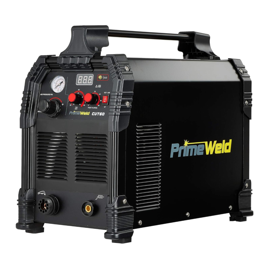
Product Introduction
The CUT60 is made by international most advantaged invert technology. 50/60Hz frequency is inverted to high frequency (frequency is over 100KHz) by V-MOSFET, then reduce voltage and commute current, inverter power supply generates powerful DC welding current through PWM technology. Because inverter technology of switch power is used, volume and weight of main transformer reduced substantially and efficiency has been increased by 30%.
The CUT60 is a non-high frequency start machine. The "blow-back" type start that is used is generally safe for use in CNC applications and is ideal for general use. Blow-back type start involves a rearward movement of the electrode within the torch head when forced by the air pressure. When air pressure is applied the movement of the electrode off its seated position against the inner surface of the circuit grounded nozzle creates a spark, energizing the plasma stream. With this machine's start type and pilot arc design, you are able to cut on any metal surface without having to contact to strike an arc which is ideal for cutting items like expanded metal or uneven surfaces. This Cutting machine has a wide range of uses which is suitable for cutting: stainless steel, alloy steel, mild steel, copper and other color metal materials.
Cutting machine has characteristics as following:
- Stabilizing.
- Reliability.
- Lightness.
- Energy-saving and no noise.
- High cutting speed.
- Cutting smoothly and no polish demands.
Specification
| Parameter | CUT60 | |
| Inverter type | MOSFET | |
| Input voltage | 1 phase AC, 110V +/- 15% | 1 phase AC, 220V +/- 15% |
| Input frequency | 50/60Hz | 50/60Hz |
| Input connector type Pre-wired for NE-MA 6-50P *adapter provided for NEMA 6-50 to NEMA 5-15 (for 220V or 1IOV operation) |  *See note |  |
| Rated input current | 43 | 48.6 |
| Rated output voltage | 92 | 104 |
| Rated output current | 20-30 | 20-60 |
| No-Load voltage | 255V | |
| Arcing start mode | Non HF style non contact start | |
| Duty Cycle | 60% @ 30 A/92 V 100% @ 23A/89.3 V | 60% @ 60 A/104V 100% @ 46 A/98.4V |
| Recommended Operating Air Pressure | 55-75 psi | |
| Nozzle Inside Hole (mm) | 1.1 mm | |
| Cutting thickness | 1/3" (8mm) | 4/5" (20mm) |
| CNC port | yes | |
| 2T/4T | yes | |
| Air Post Flow Timer | 0-60s adjustable | |
| Set Air | yes | |
| Efficiency | >=80% | |
| Power factor | 0.73 | |
| Insulation grade | F | |
| Ingress protection Rating (IP) | IP21 | |
| Weight | 15.20Kg/33.51 lbs | |
| Overall dimensions | 520 x 265 x 420mm/20.47 x 10.43 x 16.54 inches | |
Quick Setup and Use Guide
Front panel features and controls

| PowerPlasma S Features | Parameters | Purpose |
| 20-60 | Displays selected amperage until cut starts. Once cut starts, then amps display dynamically by displaying the actual output amps while cutting. While Pilot arc is engaged or when cut starts, the amps will drop to 20-30 amps until continuity is sensed and cutting arc takes over and the pilot arc disengages. |
| 0-150 psi | The gauge registers up to 150 psi, but air pressure from the compressor to the cutter should never be set above 90 psi. Air pressure to the torch while cutting should ideally be around 55-75 psi. See the PSI setting reference section. |
| Infinite | Adjusts and selects desired operating amperage. |
| N/A | The central torch connector is an all-in-one connector. This is a universal style connection which allows greater interchangeability of torches. It also greatly simplifies torch connection. When installing the connector, line up the locating tab on the torch side with the slot on the connector on the machine side connector. Fully insert the coupling and then tighten the collar nut on the torch side fitting hand tight. Do not use tools to tighten. Do not over tighten. |
| N/A | The work lead (sometimes referred to as "ground") is used to complete the circuit. The torch pilot arc may activate, but the unit will not actually cut if the work lead is not connected to the work piece. If an arc is present but the unit will not easily cut or is very slow or poor cutting any material, check and make sure work lead is connected and is connected to a clean spot on the work. |
| 0-60 Seconds | Select a post flow time that is appropriate to cool the torch and the consumables. Post flow time will depend upon the amps and length/severity of use. |
| 2T/4T | 2T is the normal position while cutting. To operate, simply press and hold the switch and cut normally. Release the switch when the cut is finished. The 4T setting allows the torch to be locked on during use. To cut in 4T mode, simply press and hold the trigger to start the arc. Release the trigger to continue cutting. Once the arc is ready to be terminated slowly press and release the switch again. Use 4T cautiously. This feature can leave the torch activated if the torch is improperly withdrawn from the cutting area. But is useful for long cuts or when mechanical cutting requiring remote activation of the torch, i.e. a linear track torch or a pipe bevel track cutter. |
| 8. Air Flow Function | Set Air | Select SET AIRto set air flow/air pressure for the torch. The operating pressure should always be set while this is in Test since it does not require the torch to be live. This allows the air to flow constantly until the switch is placed back into the normal, timed mode. To set the air pressure, turn the torch until the nozzle is facing up, then place the flow tube (clear plastic tube with ball in it) over the nozzle. Select SET AIR on the machine. With the air flowing, adjust the air pressure/flow up or down until the ball is floating in the sight window of the flow tube. If no flow tube is present or provided with your unit, then simply set the air pressure while SETAIR is selected until it is somewhere between 65-75 psi. Pressure over or under this can result in an unstable arc |
| On or Off | These indicate the status of the machine and indicate if any fault is present. If duty cycle is exceeded, the Duty Cycle light will come on and cutting will be interrupted, but the unit will continue to run and the fan will cool. Once the light goes off cutting may resume. After 5-10 minutes, if the light does not go off and cutting is still prevented, the cycle the machine off and then back on. If the Over Current light is on, recheck all wiring and connections and make sure the correct wire size and wiring has been used. Purposefully creating too long of an arc may also cause this or it could be a side effect of hitting the duty cycle limit of the machine. Cycle the machine on and off. If the light clears and cutting resumes, the fault has been cleared. If the unit will not work and/or the light remains on, contact Primeweld Tech Support. |
| N/A | To adjust the regulator, simply pull the knob up slightly until it clicks, and rotate the knob clockwise to increase the pressure or counterclockwise to decrease the pressure. To lock in the setting, push the knob down until it clicks. Do not exceed 90 psi supply pressure. Do not exceed 85 psi on the plasma cutter side of the regulator or internal leakage may result. Operating air pressure should be set to about 55-75 psi while in to Test mode. |
Rear panel features and controls

| Features | Parameters | Purpose |
| N/A | This allows the unit to be used with a CNC machine and provides the basic inputs for CNC operation. See pin-out section located in the back of this manual. |
| On/Off | The 2 pole breaker switch serves as the On/Off switch for the cutter. Always turn the cutter on and off by the switch first before using any disconnect switch. |
| 220/240V 1 phase (110 X2) Plug: NEMA 6-50P | The Plasma cutter 60 will operate on 220/240 V 50/60 Hz power, including good quality 208 V power. The wiring contains 3 separate wires. Primeweld uses standard sized wiring and correct plugs (NEMA 6-50P) for welders and plasma cutters in the US and Canada. (Other countries will vary according to regional requirements). Standard wire colors are L-1 black (hot), L-2 white (hot), and green (ground) for 1 phase 220/240 V. Do not attempt to use a 4 wire 1 phase 220/240 connection. NOTE: In many home circuits, red and black are the power wires. But in standard welding/ plasma cutting circuitry, white and black are hot wires. Green is always the ground in both circuits. There is NO neutral in a standard welder circuit. The units are shipped with a standard NEMA 6-50P plug. Always consult a licensed electrician who is aware of local codes before attempting any wiring of the welder or of the power supply circuits. Primeweld is not responsible for any mis-wiring or damage caused to the unit by incorrectly wiring the welder. If additional help is needed, contact Primeweld. Disconnect the plasma cutter when not in use. |
| N/A | The gas input connection is a thread connector with G1/4, connect the gas supply to the power supply using a hose with a correct connector. |
Installation
Input cable connection (enclose installing diagram)
- Every machine has been supplied with the relevant voltage connecting plug. The power cable must be connected to the correct power source for either plug: 110v uses pigtail adaptor plug supplies, 220v uses plug already attached on power cord end. If the Plasma Cutter is connected to a 220v Power source using a 110v plug or if the 220v power plug is connected to 110vthis may cause damage to the unit.
- Make sure power cable is connected to power receptacle securely, to eliminate any arcing or oxidization.
- Do not operate on a generator that does not have a clean sine wave and stable power output. Spiking on voltage output can cause damage to components in the Plasma cutter.
Output cable connection
- Air input line needs to be securely pushed into the quick connect fitting so as to prevent any air leaks.
- Connect the plasma torch central connector to the output terminal on the front panel using your hands.
Do not over tighten the connection as it can cause damage. - Finally connect the work lead (Ground clamp) connection to the black dinse connection.
CHECK
- Check if the plasma cutter is grounded reliably according to local standards. If used on standard breaker panel box the ground wire and panel should be already grounded according to your local code.
- Check if all connectors are firmly connected.
- Check if power voltage is correct.
Installation diagram

Operation
Turn the power switch to the "on" position. At this time, indicator light will be ON showing unit is powered on.
- Press the front panel switch to SETAIR position, there will be constant air flow, adjust the air (gas) pressure and set to between 55 to 75psi. Please refer to the air pressure setting.
- Press the torch trigger and you should have a plasma arc from the tip.
![]()
The plasma arc can cause extreme burns, keep tip away from your body at all times. - Set the amps to your required cutting thickness.
- Keep tip approximately 1/8" from workpiece and move the tip as you see the cutting arc below the workpiece showing you that the cut is completely through the metal. Move the torch in a smooth continuous motion for best cutting results.
- Recommended compressor capacity 5cfm @ 80psi, 20 gallon tank.
- 2T/4T SWITCH:
2T - press this button on the cutting torch to start the metal cutting process, release this button to end this process.
4T - press this button on the cutting torch to start the metal cutting process, releasing this button does not end this process. Press and release this button again to end the metal cutting process.
Operation environment
- The Plasma cutter can perform in temperatures between -10 and +40 degrees centigrade with a maximum dampness level of 80%.
- Avoid operating with the sun directly on the unit as this will increase the inside temperature and decrease duty cycle.
- Keep machine dry and stored or use in a dry location out of the elements.
- Do not use the Plasma cutter in environments that have a high concentration of dust or corrosive gas in the air.
SAFETY
- Make sure the work area is adequately ventilated.
The Plasma cutter is supplied with Axial-flow fan to cool both upper and lower heat sinks and boards.
NOTES: Exhaust and Intake vents must be clear of any obstructions in order to allow the Plasma cutter to adequately get air flow for cooling. A minimum of twelve inches is required for air flow to and from all vents. - Correct voltage must be used for all amp settings either on 110v or 220v the voltage drop cannot go lower than 105 volts on 110v or 210 volts on 220v. Do not exceed load or operate at maximum duty cycle on a constant basis as this will shorten the life of various internal components.
- Voltage Range
The power voltage range of the plasma cutter is shown on the technical data page. Automatic voltage compensation circuits will help prevent the unit from exceeding the allowable range. However, if the input voltage is too high, it could damage components. - Thermal overload sensors will switch on if the unit exceeds the duty cycle. Fans will continue to run but no power is available. Once the unit is cooled down, the power switch can be turned OFF and then back ON to continue cutting. Powering the unit OFF and ON resets the thermal overload switch. The red O.C. overload light appears when the Plasma cutter hits the duty cycle.
CUTTING NOTES
- When cutting thinner material, up to 2 to 3 mm, you can drag tip the torch and the cutting tip can touch the material as you cut. For thicker materials it is recommended that a distance of 3 mm (1/16" to 1/8")distance be kept from the cutting surface. This not only gives better consumable life but it increases cut quality.
- The Work piece clamp or grounding clamp must be placed on a clean section of metal, as close as possible to the cutting area in order to have a good ground and maximum efficiency. If the ground is bad, problems will arise with poor cutting quality and loss of cutting arc.
Basic Theory and Function
The design of the blowback start may cause a slight delay in the arc as the air pressure must built inside the torch tubing and head to create the pressure needed to force the electrode off the nozzle seat. This may take up to a second. If the torch does not light after 3 seconds, let go of the trigger and press it again. If the start or arc is erratic check nozzle and electrode for tightness and wear.
Edge Starts are the best type of start if possible to promote consumable and torch life. This reduces blow back of molten material and allows a smooth gradual start of the cut.

- Line up the hole on the tip of the electrode on the edge of the cut. Hold torch perpendicular to the cut initially, about 1/16" off the metal. Slide the yellow safety lock and squeeze the trigger. Wait for arc to start.
- Once the arc starts, wait for the arc to penetrate all the way through the metal.
- As the torch penetrates its flame all the way through the metal, tilt the torch so there is a slight lead in the flame if metal is thin. If it is thick, keep holding torch in a nearly vertical position.
- Begin moving the torch in the direction of the cut. Maintain 1/16" standoff height.
- Move the torch fast enough so the sparks and flame trail from the bottom edge at an angle of no more than 30° and no less than 10° from perpendicular to the metal. Excess angle of sparks/flame indicate too fast of travel speed or practical cut capacity has been reached. Little or no angle indicates too slow of travel speed.
Piercing starts often result in rapid consumable wear and excess blow back of molten metal deposited onto torch and consumables. This should be done only as necessary.

- Tilt the torch in the direction of travel or toward the side of the metal to be discarded or wasted at a 40° to 60° angle. Slide the yellow safety lock and squeeze the trigger. Wait for arc to start.
- Once the arc starts, wait for the arc to transfer from pilot arc to the cutting arc.
- As the torch penetrates it flame at an angle rotate the torch slowly to the vertical position, as the arc penetrates the metal. Tilt the torch from 0°-15° for thin metal cuts, or hold it nearly perpendicular for thicker metal cuts.
- Begin moving the torch in the direction of the cut. Maintain 1/16" standoff height.
- Move the torch fast enough so the sparks and flame trail from the bottom edge at an angle of no more than 30° and no less than 10° from perpendicular to the metal. Excess angle of sparks/flame indicate too fast of travel speed or practical cut capacity has been reached. Little or no angle indicates too slow of travel speed.

If you use a standoff guide with the torch, it must be adjusted to provide no more than 1/8" standoff, less if possible. Long standoff heights reduce cut capacity and quality. It also promotes rapid consumable wear and can prevent the pilot arc from transferring.
TIP: For longer consumable life do not use the pilot arc unnecessarily. Do not fire the torch unless you are near the metal and ready to cut.

Check consumables regularly for wear and change them out before they are completely worn. Allowing the consumables to wear until they quit working may damage related torch components, creating a more costly repair.

AN EXAMPLE OF CUTTING A LEAD-IN WHEN CUTTING OUT A DISK SHAPED OBJECT

AN EXAMPLE OF CUTTING A LEAD-IN WHEN CUTTING HOLE IN AN OBJECT

When cutting an object, particularly a pattern shape, where the torch must pierce or re-fire in-line at an intersection of a cut, a lead-in cut should be employed. A lead-in is a cut that is made in the disposable part (also known as a drop) of the object to "lead" into the main part of the cut so that the destructive force of the arc is not directed into the desirable side of the cut itself. Also, all plasma cutters exhibit some angularity or bevel in the cut which is greater on one side than the other. Keep this in mind when cutting an object to size so that too much metal is not accidentally removed.
Maintenance
Procedures not specifically explained in this manual must be performed only by a qualified technician.

TO PREVENT SERIOUS INJURY FROM ACCIDENTAL OPERATION OR ELECTRIC SHOCK:
Make sure the power Switch of the Plasma Cutter is in its "OFF" position and that the Plasma Cutter is unplugged from the electrical outlet before performing any inspection, maintenance, or cleaning procedures.
TO PREVENT SERIOUS INJURY FROM PLASMA CUTTER FAILURE:
Do not use damaged equipment. lf abnormal noise, vibration, or leaking air occurs, have the problem corrected before further use.
Cleaning and Maintenance
Note: These procedures are in addition to the regular checks and maintenance explained as part of the regular operation of the air-operated tool.
- BEFORE EACH USE, disassemble Torch, inspect and replace worn components, then reassemble Torch tightly.
- Daily - Air Supply Maintenance: Every day, maintain the air supply according to the component manufacturers' instructions. Drain the dryer regularly. Performing routine air supply maintenance will allow the tool to operate more safely and will also reduce wear on the tool.
- PERIODICALLY, blow the dust from the cooling vents with compressed air. If the unit repeatedly shuts down from thermal overload, stop all use.
- Have the Plasma Cutter inspected and repaired by a qualified service technician.
- Opening the Plasma Cutter will void the warranty, and may result in damage to equipment or possible personal injury. DO NOT OPEN THE HOUSING Any repairs must be completed by a qualified technician.
- Store the Plasma Cutter and accessories in a clean and dry location out of reach of children.
![]()
If the supply cord of this Plasma Cutter is damaged, it must be replaced only by a qualified service technician.
Troubleshooting
Be CERTAIN to shut off the Plasma Cutter, and disconnect it from power and air before adjusting, cleaning, or repairing the unit. A technician should discharge all capacitors before performing any internal procedures.
FAN RUNS WHEN SWITCHED ON BUT ARC WILL NOT IGNITE
Check Air Switch
- AIR SWITCH SET TO "SET AIR"
Set Air Switch to "2T" or "4T". "SET AIR" is ONLY used to set air pressure, it does not allow normal operation. - AIR SWITCH SET TO "2T" or "4T"
Air pressure too high or too low. Check the Cutter's Air Pressure Gauge. Set between 60 - 75 PSI.- AIR PRESSURE TOO HIGH
Set Compressor's Air Pressure Regulator between 80 - 120 PSI. - AIR PRESSURE CORRECT
Check that the grounding point and the metal being cut are both clean, dry, and free from paint, oil, or dirt.
These sections need to conduct electricity efficiently.- DIRTY OR COATED METAL
Use a wire wheel brush or sander (not included) to thoroughly clean both the grounding point and the area that will be cut.
If any cleaners are used, allow them to dry thoroughly before continuing. - METAL IS CLEAN IN BOTH AREAS
Torch isn't maintaining contact with the workpiece.- Maintain a 1/16" distance from workpiece at all times.
- Disassemble Torch, inspect and replace worn components, then reassemble Torch tightly.
- Torch is moving too slowly across the metal and cutting the material from underneath, breaking contact. Move Torch more quickly.
- DIRTY OR COATED METAL
- AIR PRESSURE TOO LOW
- Verify that the compressor is delivering 5 CFM @ 80 PSI.
- Set Cutter's Air Pressure Regulator between 60 - 75 PSI.
- AIR PRESSURE TOO HIGH
ARC IGNITES FOR SEVERAL SECONDS BUT THEN GOES OUT
Air pressure too high or too low.
Check the air pressure setting on both the Compressor and the Cutter.
- AIR PRESSURE TOO HIGH
Set Compressor's Air Pressure Regulator between 80 - 120 PSI. - AIR PRESSURE CORRECT
Check that the grounding point and the metal being cut are both clean, dry, and free from paint, oil, or dirt.
These sections need to conduct electricity efficiently.- DIRTY OR COATED METAL
Use a wire Wheel brush or sander (not included) to thoroughly clean both the grounding point and the area that will be cut.
If any cleaners are used, allow them to dry thoroughly before continuing. - METAL IS CLEAN IN BOTH AREAS
Torch isn't maintaining contact with the workpiece.- Maintain a 1/16" distance from workpiece at all times.
- Disassemble Torch, inspect and replace worn components, then reassemble Torch tightly.
- Torch is moving too slowly across the metal and cutting the material from underneath, breaking contact. Move Torch more quickly.
- DIRTY OR COATED METAL
- AIR PRESSURE TOO LOW
- Verify that the compressor is delivering 5 CFM @ 80 PSI.
- Set Cutter's Air Pressure Regulator between 60 - 75 PSI.
- Verify air flow by performing "Test Air Flow".
CUT GOES ONLY PARTIALLY THROUGH THE WORKPIECE
Material being cut is too thick.
See Maximum Cutting Thickness.
- TOO THICK
Use a more powerful PlasmaCutter. - WITHIN THICKNESS RANGE
Turn up the Output Current Knob and try again at a slower Torch travel speed.- PROBLEM CORRECTED
Take note of the setting required for this metal thickness. - PROBLEM PERSISTS AT MAXIMUM CURRENT SETTING
Air pressure too low.
Set Cutter's Air Pressure Regulator between 60 - 75 PS'.- AIR PRESSURE TOO LOW
- Verify that the compressor is delivering 5 CFM @ 80 PSI.
- Set Cutter's Air Pressure Regulator between 60 - 75 PSI.
- AIR PRESSURE CORRECT
Disassemble Torch, inspect and replace worn components, then reassemble Torch tightly.- TORCH IN GOOD CONDITION
Cut at a slower pace, the arc may not have enough time to cut through the workpiece.
Maximum cutting speeds:
5/8" Mild Steel @ 17.7 'PM (Rated)
3/4" Mild Steel @ 11.8 'PM (Severance) - DAMAGED COMPONENTS FOUND
Disassemble Torch, inspect and replace worn components, then reassemble Torch tightly.
- TORCH IN GOOD CONDITION
- AIR PRESSURE TOO LOW
- PROBLEM CORRECTED
FAST CUTTING TIP WEAR OR EXCESSIVE SLAG FORMATION
These two problems have similar causes and will often appear simultaneously.
The same diagnostic procedures and remedies apply to both.
- Current set too high; cut at lowest setting possible for the metal being cut.
- PROBLEMS REDUCED
Take into account the thickness and type of metal to be cut before starting. Thinner materials require lower amp settings. - PROBLEMS PERSIST AT LOWEST PRACTICAL SETTING
Disassemble and inspect Torch.- DAMAGED COMPONENTS FOUND
Replace worn components, then reassemble Torch tightly. - TORCH IN GOOD CONDITION
Air supply pressure may be inadequate:- Verify that the compressor is delivering 5 CFM @ 80 PSI.
- Set Cutter's Air pressure Regulator between 60 - 75 PSI.
Additional factors:
- Maintain a 1/16" distance from workpiece at all times.
- Move Torch at proper rate. Maximum cutting speeds:
5/8" Mild Steel @ 17.7 IPM (Rated)
3/4" Mild Steel @ 11.8 IPM (Severence) - Compare workpiece thickness to Maximum Cutting Thickness.
- DAMAGED COMPONENTS FOUND
- PROBLEMS REDUCED
Reference
CNC CONNECTOR PIN OUT
Pin and board numbers correspond to each other. 8 is not used

- Pins 1 and 2 activate (turn on) the plasma cutter.
- Pin 9 and 10 gives the "OK to Move" signal. These are Dry "N.O." style contacts. It is nonelectronic switch that closes when the pilot arc transfers to cutting arc. Sometimes referred to as "Arc OK".
- Pins 5 and 7 provide the raw, undivided arc voltage, which is used by some controllers to adjust the height of the torch (THC). This is the actual cutting voltage. It runs through 2-100kΩ resistors to prevent arcing at the connector plug. Some controllers may use the raw voltage, and is dependent upon the impedance of the input. CandCNC* controller and Torchmate* do not use this voltage.
- Pins 4 and 6 provide the divided arc voltage. The CNC circuit board to create 1/50th of the raw arc voltage. It may be used by some controllers for torch height control (HTC).
- Pins 11 and 12 provide the divided arc voltage. The CNC circuit board to create 1/16 th of the raw arc voltage. It may be used by some controllers for torch height control (HTC).
- Pin 3 is what some controller manufacturers refer to as "Ground" this is connected directly to the workpiece lead, which is actually a positive polarity. If the controller has a pin for ground this is likely the pin to use.
NOTE: Do not connect anything directly to the output terminals or leads. Do not connect anything from the controller to the chassis of the cutter, especially a ground lead. Do not install any kind of converter or divider inside the machine.
* Prime Weld does not particularly endorse or recommend these brands and is not affiliated with them in any way. They are mentioned as a common reference only. For specific recommendations regarding connection, contact the manufacturer of the CNC equipment/controllers
PSI SETTING REFERENCE TABLE
| Output AMP | Air Pressure (PSI) Cutting |
| 20 A | 55 |
| 30 A | 55 |
| 40 A | 55 |
| 50 A | 65 |
| 60 A | 75 |
CUTTING SPEED REFERENCE TABLE
| Mild Steel | |||||||
| AMPS | PSI | Material Thickness | Torch-to-Work Distance | Optimum Cut Speed | |||
| Inch | mm | Inch | mm | IPM | mm/min | ||
| 20 | 55 | 26GA | 0.5 | 0.06 | 1.5 | 236.22 | 6000 |
| 30 | 55 | 16GA | 1.6 | 110.24 | 2800 | ||
| 40 | 55 | 10GA | 3.4 | 86.61 | 2200 | ||
| 45 | 60 | 3/16" | 5 | 62.99 | 1600 | ||
| 45 | 60 | 1/4" | 6 | 47.24 | 1200 | ||
| 50 | 65 | 1/3" | 8 | 43.31 | 1100 | ||
| 55 | 70 | 2/5" | 10 | 39.37 | 1000 | ||
| 60 | 75 | 1/2" | 12 | 23.62 | 600 | ||
| 60 | 75 | 5/8" | 16 | 17.72 | 450 | ||
| 60 | 75 | 3/4" | 20 | 11.81 | 300 | ||
| Stainless | |||||||
| AMPS | PSI | Material Thickness | Torch-to-Work Distance | Optimum Cut Speed | |||
| Inch | mm | Inch | mm | IPM | mm/min | ||
| 20 | 55 | 26GA | 0.5 | 0.06 | 1.5 | 188.98 | 4800 |
| 30 | 55 | 16GA | 1.6 | 88.19 | 2240 | ||
| 40 | 55 | 10GA | 3.4 | 69.29 | 1760 | ||
| 45 | 60 | 3/16" | 5 | 50.39 | 1280 | ||
| 45 | 60 | 1/4" | 6 | 37.80 | 960 | ||
| 50 | 65 | 1/3" | 8 | 34.65 | 880 | ||
| 55 | 70 | 2/5" | 10 | 31.50 | 800 | ||
| 60 | 75 | 1/2" | 12 | 18.90 | 480 | ||
| 60 | 75 | 5/8" | 16 | 14.17 | 360 | ||
| 60 | 75 | 3/4" | 20 | 9.45 | 240 | ||
| Aluminum | |||||||
| AMPS | PSI | Materia Thickness | Torch-to-Work Distance | Optimum Cut Speed | |||
| Inch | mm | Inch | mm | IPM | mm/min | ||
| 20 | 55 | 26GA | 0.5 | 0.06 | 1.5 | 271.65 | 6900 |
| 30 | 55 | 16GA | 1.6 | 126.77 | 3220 | ||
| 40 | 55 | 10GA | 3.4 | 99.61 | 2530 | ||
| 45 | 60 | 3/16" | 5 | 72.44 | 1840 | ||
| 45 | 60 | 1/4" | 6 | 54.33 | 1380 | ||
| 50 | 65 | 1/3" | 8 | 49.80 | 1265 | ||
| 55 | 70 | 2/5" | 10 | 45.28 | 1 150 | ||
| 60 | 75 | 1/2" | 12 | 27.17 | 690 | ||
| 60 | 75 | 5/8" | 16 | 20.37 | 517.5 | ||
| 60 | 75 | 3/4" | 20 | 13.58 | 345 | ||
Circuit diagram appendix

Parts List and Diagram

Parts List
| part | Description | Qty |
| 1 | Back Left Plastic Part | 1 |
| 2 | Back Left Iron Part | 1 |
| 3 | Back Right Plastic Part | 1 |
| 4 | Back Right Iron Part | 1 |
| 5 | Beam | 2 |
| 6 | Upper PC Board | 1 |
| 7 | Plastic Bracket | 1 |
| 8 | Radiator | 4 |
| 9 | Middle PC Board | 1 |
| 10 | 12 pins CNC Socket | 1 |
| 11 | Power Cord Clip | 1 |
| 12 | Power Cord | 1 |
| 13 | Fan Hood | 1 |
| 14 | Coolin Fan | 1 |
| 15 | Fan Cover | 1 |
| 16 | Air Inlet | 1 |
| 17 | Oil Water Filter | 1 |
| 18 | Main Switch | 1 |
| 19 | Circuit Breaker Bracket | 1 |
| 20 | CNC Board | 1 |
| 21 | Power PC Board | 1 |
| 22 | Inductor | 1 |
| 23 | Air Flow Control Valve | 1 |
| 24 | PC Board Bracket | 1 |
| 25 | 2T/4T Control Board | 1 |
| 26 | Switch Control Board | 1 |
| 27 | Bottom Housin | 1 |
| 28 | Quick Connector | 1 |
| 29 | Central Connector | 1 |
| 30 | Potentiometer | 2 |
| 31 | Output Current Knob | 2 |
| 32 | Air Pressure Regulator | 1 |
| 33 | Air Pressure Gauge | 1 |
| 34 | Switch | 1 |
| 35 | Front Panel PC Board | 1 |
| 36 | PC Board Right Bracket | 1 |
| 37 | PC Board Left Bracket | 1 |
| 38 | Main Control PC Board | 1 |
| 39 | Right Rubber Footpad | 2 |
| 40 | Right Machine Foot Plastic Part | 2 |
| 41 | Left Rubber Foot ad | 2 |
| 42 | Left Machine Foot Plastic Part | 2 |
| 43 | Front Right Iron Part | 1 |
| 44 | Front Right Plastic Part | 1 |
| 45 | Front Left Iron Part | 1 |
| 46 | Front Left Plastic Part | 1 |
| 47 | Handle Seat | 2 |
| 48 | To Housing | 1 |
| 49 | Handle | 1 |
CALL US AT
856-500-2000
Documents / ResourcesDownload manual
Here you can download full pdf version of manual, it may contain additional safety instructions, warranty information, FCC rules, etc.
Advertisement


Need help?
Do you have a question about the CUT60 and is the answer not in the manual?
Questions and answers