Table of Contents
Advertisement
Advertisement
Table of Contents

Related Manuals for Hisense BCD-440WPZ/HC1(H)


Summary of Contents for Hisense BCD-440WPZ/HC1(H)
- Page 1 Refrigerator Service Manual Model:BCD-440WPZ/HC1(H)
-
Page 2: Table Of Contents
Contents 1.Warnings and precautions for safety ........2 2.Appearance and structure 2.1 View of the appliance .............3 2.2 Wind channel structure ............4 2.3 Evaporator structure ..............5 ............6 2.4 Compressor room structure ..............7 3.Basic parameters 4.Operation and functions 4.1 Display controls ..............8 4.2 Ice maker.... -
Page 3: Warnings And Precautions For Safety
1.Warning and precautions for safety 1 Warning and precautions for safety Please observe the following safety precautions in order to use safely and correctly the refrigerator and to prevent accident and danger during repair. 1. Be care of an electric shock. Disconnect power cord from wall outlet and wait for more than three minutes before replacing PCB parts.Shut off the power whenever replacing and repairing electric components. -
Page 4: Appearance And Structure
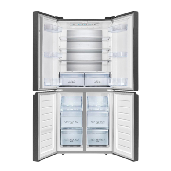
2.Appearance and structure 2 Appearance and structure 2.1 View of the appliance... -
Page 5: Wind Channel Structure
2.Appearance and structure 2.2 Wind channel structure... -
Page 6: Evaporator Structure
2.Appearance and structure 2.3 Evaporator structure Capillary Accumulator Sensor Evaporator Fuse Heater... -
Page 7: Compressor Room Structure
2.Appearance and structure 2.4 Compressor room structure Dry filter Electric box Power cord Compressor Evaporation dish 6 Motorized value... -
Page 8: Basic Parameters
3.Basic parameters 3 Basic parameters Content Unit Value Voltage / frequency V/Hz 110-115/60 Rated current Rated input power Defrost power Net capacity Net capacity fridge co mpartmen (Fridge/Chill) Net capacity free zer comp artme nt Energy efficiency class Climate class (SN=10~32°C, SN、N、ST N=1 6~32°C, ST=16~38°C, T=16~43°C) Refigerator room temperatu re... -
Page 9: Operation And Functions
4.Operation and functions 4 Operation and functions 4.1 Display controls Use your appliance according to the Ice Control following control regulations your This button controls the ice maker. appliance has the corresponding functions You can touch the "Ice On/Off" and modes as the control panels showed button to control the ice maker. - Page 10 4.Operation and functions 4.1 Display controls freeze items inside with maximum speed. S uper Cool icon “ ” will be “ ” We recommend that you let the appliance illuminated and the fridge temperature operate for 24 hours first. “Super Freeze” setting will display 34 automatically switches off after 52 hours.
- Page 11 4.Operation and functions 4.1 Display controls door open for a long time when using the cleared by closing the door. appliance. The door alarm can also be...
-
Page 12: Ice Maker
4.Operation and functions 4.2 Ice Maker 4.2.1 Remove ice maker 1. Open the freezer door, take the ice storage box and ice maker cover out. 4. Unplug two terminals, then take out the 4. Unplug two terminals, then take out the ice maker part. - Page 13 4.Operation and functions 3. Remove wire line from two buckles in 3. Remove wire line from two buckles in the direction of arrow one by one. the direction of arrow one by one. 7. Pull the water pipe connector part out 7.
-
Page 14: Defrost Mode
4.Operation and functions 4.3 Defrost mode 4.3.1 Start condition When compressor accumulated running time reach the setting point (depends on the environment temperature) it will enter defrost mode automatically. 4.3.2 Defrost flow Start Compressor stops Evaporator fan stops Damper stops Defrost heater works Evaporator temperature reach the setting point,exit defrost mode... -
Page 15: Compulsory Defrost Mode
4.Operation and functions 4.4 Compulsory Defrost mode 4.4.1 Start condition When buttons are unlocked,touch and hold fridge button and fresh choice button at the same time for 5 seconds,it will enter special function selecting mode after a buzzing sound.There will be a signal blinks at freezer display area,touch the unlock button,when only the longest square blinks,stop touching the button.It will enter compulsory defrost mode after 10 seconds. -
Page 16: Error Code
4.Operation and functions 4.5 Error display 4.5.1 Error code C ode D isplay ar ea Pr oble m C omm unication s ending Fridge tempe rature dis play area malfunctions R efrigerator fan mo tor Fridge tempe rature dis play area malfunctions R efrigerator s ensor Fridge tempe rature dis play area... - Page 17 4.Operation and functions 4.5 Error display 4.5.2 Checking method 4.5.2.1 Refrigeartor&freezer&evaporator sensor error Start Is the sensor connector Plug the terminal well plug well? Is the sensor connecting Repair the wiring wiring open circuit or short circuit? Change the sensor Is the sensor OK? Change the mainboard...
- Page 18 4.Operation and functions 4.5 Error display 4.5.2 Checking method 4.5.2.1 Refrigeartor&freezer&evaporator sensor error Note: 1.Refrigerator sensor corresponding pin No.2 and No.6 on CN11 connector of mainboard. 2.Freezer sensor corresponding pin No.2 and No.7 on CN11 connector of mainboard. 3.Environment sensor corresponding pin No.2 and No.5 on CN11 connector of mainboard.
- Page 19 4.Operation and functions 4.5 Error display 4.5.2 Checking method 4.5.2.3 Communication error Start Is the connecting wiring Repair the wiring between display panel and mainboard broken? Change the display Is the display panel OK? panel Change the mainboard...
- Page 20 4.Operation and functions 4.5 Error display 4.5.2 Checking method 4.5.2.3 Communication error Note: Communication sensor corresponding pin No.1~4 on CN8 connector of mainboard.
- Page 21 4.Operation and functions 4.5 Error display 4.5.2 Checking method 4.5.2.4 Freezer fan motor error Start Is the fan motor connector Plug the connector well plug well? Is the fan motor Repair the wiring connecting wiring broken? Change the fan motor Is the fan motor OK? Change the mainboard Note:...
-
Page 22: Troubleshooting
5.Troubleshooting 5.1 Common problem and checking Problem Possible cause & Solution Check whether the power cord is plu gg ed into the power outlet p roperly Check the fuse or circuit of your power su pp ly, replace if necessary Ap pliance is not worki ng correctly The ambient temperature is too l ow. - Page 23 5.Troubleshooting Problem Possible cause & Solution Check that the air outlets are not blocked by food and ensure food A layer of frost is placed within the appliance to allow sufficient ventilation. Ensure occurs in the that door is fully closed. To remove the frost,please refer to compartment cleaning and care chapter.
-
Page 24: Faulty Start
5.Troubleshooting 5.2 Faulty start Start Plug the power cord Has the power cord plugged well into the power outlet? Plug the terminals Are mainboard terminals well plugged well? Change the Is mainboard output mainboard power OK? Change the Is the compressor OK? compressor Check connectors and sensors... -
Page 25: Refrigeration Failure
5.Troubleshooting 5.3 Refrigeration failure 5.3.1 Freezer compartment Start Any error code? Refer to “4.4 Error dispaly” chapter Change the Is the compressor Does compressor compressor work? Is the PTC starter Check the or overload protector mainboard Change the PTC starter or overload protector Change the Does Fan motor... - Page 26 5.Troubleshooting 5.3 Refrigeration failure 5.3.1 Freezer compartment Do doors open Explain not to open doors frequently frequently? Is Temp. fuse OK? Change the Temp. fuse Is defrost heater Change the defrost heater Is there ice blockage on evaporator? Check ice formation on Eva.
- Page 27 5.Troubleshooting 5.3 Refrigeration failure 5.3.2 Refrigerator compartment Start Any error code? Solve error code problems Change the Does the damper work? Is the damper OK? damper Change the Is wiring connection mainboard Is the sensor OK? Check the wiring Change the sensor and check connector Is freezer compartment Refer to 5.3.1...
-
Page 28: Thick Frost In Freezer Compartment
5.Troubleshooting 5.4 Thick frost in freezer compartment Start Gap between Is dew foramed on the Change the door gasket and door gasket surface? gasket cabinet? Reassemble the Is door hanged door down? Do doors open frequently? Explain not to open doors too frequently Is the appliance too close to heat... -
Page 29: Dew In Refrigerator Compartment
5.Troubleshooting 5.5 Dew in refrigerator compartment Start Gap between Change the door Is dew foramed on the gasket and gasket door gasket surface? cabinet? Is the door Reassemble the hanged down? door Does the door open too frequently? Explain not to open doors too frequently Is the appliance too close to heat sources? -
Page 30: Low Temperature Of Vegetable Vase
5.Troubleshooting 5.6 Low temperature of vegetable vase Start Is refrigerator temperature setting too cold? Counsel to use warmer temperature setting Is the damper OK? Change the damper Is the mainboard Check the mainboard output power OK? Change the sensor Is the sensor OK? Check the sensor connection and repair... -
Page 31: Breaking Of Light
5.Troubleshooting 5.7 Breaking of light Start Is the light disconnected or broken? Change the light Is the door switch OK? Change the door switch Check the door switch connection and repair... -
Page 32: Noise
5.Troubleshooting 5.8 Noise 5.8.1 Compressor noise Start Is the appliance leveled? Level the appliance by adjusting the bottom feet Are the adjustable bottom feet broken? Change the adjustable bottom feet Is the noise from compressor itself? Change the compressor Add a rubber absorber to reduce the vibration... - Page 33 5.Troubleshooting 5.8 Noise 5.8.2 Refrigerator flowing noise Start Water flowing or hiss sound from the appliance? Attache a gum absorber on the capillary tube Hiss or sizzling sound from refrigerant when comp. starts/stops? Attach a gum absorber on the accumulator Sound from freezer compartment when compressor’s running? Fasten the evaporator...
- Page 34 5.Troubleshooting 5.8 Noise 5.8.3 Fan motor noise Start Is the fan damaged or transformed? Change the fan Is the fan touching surround? Set the fan right,avoid to touch surround Is the fan moving or shaking? Fasten the fan motor Sound from fan itself or vibration when working? Change the fan motor Explain to the customer...
- Page 35 5.Troubleshooting 5.8 Noise 5.8.4 Pipe noise Start Are pipes touching in the compressor room? Separate the touching pipes Does evaporation dish make noise by touching the pipe? Check the cushion between pipe and evaporation dish and repair Is pipe itself shaking strongly? Move or change the points of vibration absorber on pipes to reduce shaking...
-
Page 36: Circuit And Checking
6.Circuit and checking 6 Circuit and checking 6.1 Circuit diagram... -
Page 37: Mainboard And Display Panel
6.Circuit and checking 6.2 Mainboard 6.2.1 Checking method If the problem is probably caused by mainboard,change it directly to confirm. 6.2.2 Removing the mainboard 1.Unplug the appliance 2.Remove the screws of electric box cover by screwdriver,as picture 1. 3.Remove the electric box cover,as picture 2. 4.Unplug the terminals on the mainboard,as picture 3. -
Page 38: Compressor
6.Circuit and checking 6.3 Compressor 6.3.1 Basic parameters Input voltage:110-115V Input frequency:60Hz 6.3.2 Checking method 1.Compressor will start 10 seconds after power-on,if it starts unsuccessfully,remove the electric box cover and check. 2.Check the connecting wiring between compressor and mainboard and repair if it is broken. 3.Use a multimeter to measure voltage between pin No.1 and No.5 on CN3 connector of mainboard,if the voltage equal to electric supply power,it means the compressor is broken,change it;If not,change the... - Page 39 6.Circuit and checking 6.3.3 Removing the PTC starter and overload protector 1.Unplug the appliance 2.Remove the screws of protector box by screwdriver,as picture 1. 3.Pry up the protector box from top by screwdriver,as picture 2. 4.Unplug the overload protector,as picture 3. 5.Unplug the PTC starter,as picture 4.
-
Page 40: Fan Motor
6.Circuit and checking 6.4 Fan motor 6.4.1 Basic parameters Rated voltage:DC12V Rated input power:2W 6.4.2 Checking method 1.Check the connecting wiring of fan motor is well or not,repair if it is broken.The fan motor corresponding pin No.4~6 on CN9 connector of mainboard,as the drawing below. - Page 41 6.Circuit and checking 6.4.3 Removing the fan motor 1.Unplug the appliance 2.Remove the screws of freezer wind channel component by screwdriver,as picture 1. 3.Remove the wind channel component and unplug the terminals,as picture 2. 4.Remove the screw of the wind channel component by screwdriver, as picture 3.
-
Page 42: Light
6.Circuit and checking 6.6 Light 6.6.1 Basic parameters Rated voltage:DC12V 6.6.2 Checking method 1.Check the connecting wiring between light and mainboard is well or not,repair if it is broken.Refrigerator light corresponding pin No.1 ~ No.4 on CN5 ,as the drawing below. 2.Check output voltage corresponding light of the mainboard,if it is 12V,it means the mainboard is OK,change the light;If not,it means the mainboard is broken,change it. - Page 43 6.Circuit and checking 6.6.3 Removing the light 1.Unplug the appliance 2.Pry up the light cover from the buckles by screwdriver,as picture 1. 3.Remove the light cover,as picture 2. Pry up the light from the buckles by screwdriver ,as picture 3. Unplug the terminal of the light,as picture 4.
- Page 44 6.Circuit and checking 6.7 Door switch 6.7.1 Basic parameters Input voltage:5V Rated current:0.05A 6.7.2 Checking method Check the connecting wiring of door switch is well or not,repair if it is broken. Door switch corresponding pin No.8 ~ No.11 on CN8 connector of mainboard , as the drawing below..
-
Page 45: Temperature Fuse
6.Circuit and checking 6.8 Temperature fuse 6.8.1 Basic parameters ℃ Max fusing-off temperature:72 Load voltage115V Load current:10A 6.8.2 Checking method Use a multimeter to measure resistance between the two terminals of the temperature fuse,if it is open circuit,change the fuse. - Page 46 6.Circuit and checking 6.8.3 Removing the temperature fuse 1.After removing the freezer wind channel component,unplug the terminals,as picture 1. 2.Remove the screws of evaporator by screwdriver,as picture 2. 3.Separate the evaporator component from the cabinet and remove the foams at left side and right side,as picture 3. 4.Cut the self locking ties that fastening the temperature fuses by knife and then remove the fuses,as picture 4.
-
Page 47: Defrost Heater
6.Circuit and checking 6.9 Defrost heater 6.9.1 Basic parameters Rated voltage:AC115V Rated power:224W 6.9.2 Checking method 1.Enter compulsory defrost mode,use a multimeter to measure voltage between pin No.2 and No.6 on VH-6 connector of the mainboard,if the voltage doesn't equal to electric supply power,it means the heater is broken,change it. - Page 48 6.Circuit and checking 6.9.3 Removing the defrost heater 1.After removing the freezer wind channel component,unplug the terminals,as picture 1. 2.Remove the screws of evaporator by screwdriver,as picture 2. 3.Separate the evaporator component from the cabinet and remove the foams at left side and right side,as picture 3. 4.Cut the self locking ties that fastening the heater by knife,as picture 4.
-
Page 49: Electromagnetic Valve
6.Circuit and checking 6.10 electromagnetic valve 6.10.1 Checking method Fault phenomenon 1 Leak : Detection method Use soap water coating on the welding place of the : electromagnetic valve, pour the refrigerants into the system, to see if having the bubble, If yes, meaning the electromagnetic valve itself has the leakage. -
Page 50: Ice Maker
6.Circuit and checking 6.11 Ice maker 6.11.1 Checking method Step 1.Check water line connection Step 2.Touch and hold “Super Freeze” button and “Freezer” button at the same time for 3 seconds in 15 minutes after power-on, ice tray will be turned, if not, please replace the ice maker part. - Page 51 6.Circuit and checking...
-
Page 52: Refrigeration System
7.Refrigeration system repair 7.1 Refrigeration system The refrigerator system is double cycle wind cooling system: Compressor discharges high temperature high pressure R600a gas refrigerant Refrigerant enters evaporation pipe,condenser and anti-condensation pipe one after another, then becomes middle temperature high pressure liquid after condensation Refrigerant enters dry filter,water and imperity will be filtrated... - Page 53 7.Refrigeration system repair 7.1 Refrigeration system...
-
Page 54: Summary Of Repair
7.Refrigeration system repair 7.2 Summary of repair... -
Page 55: Regulation Of Repair
7.Refrigeration system repair 7.3 Regualation for repair... -
Page 56: Practical Work Of Repair
7.Refrigeration system repair 7.4 Practical work for repair... - Page 57 7.Refrigeration system repair 7.4 Practical work for repair...
-
Page 58: Brazing Reference Drawing
7.Refrigeration system repair 7.5 Brazing reference drawing 7.5 Brazing reference drawing Refrigearnt flowing direction Welding points...
Need help?
Do you have a question about the BCD-440WPZ/HC1(H) and is the answer not in the manual?
Questions and answers
Do you have a parts number for the circuit boards?