Table of Contents
Advertisement
Quick Links
PCI-AD64 User Manual
1 MS/s, 64-ch, 16-bit Analog Input Board
S
UPPORT
This manual relates to the following boards: PCI-AD64SU.
W
ARRANTY
All products manufactured by ICP DAS are warranted against defective materials
for a period of one year from the date of delivery to the original purchaser.
W
ARNING
ICP DAS assumes no liability for damages consequent to the use of this product.
ICP DAS reserves the right to change this manual at any time without notice. The
information furnished by ICP DAS is believed to be accurate and reliable. However,
no responsibility is assumed by ICP DAS for its use, nor for any infringements of
patents or other rights of third parties resulting from its use.
C
OPYRIGHT
Copyright © 2021 by ICP DAS. All rights are reserved.
T
RADEMARKS
Names are used for identification purposes only and may be registered
trademarks of their respective companies.
C
US
ONTACT
If you have any questions, feel to contact us by email at:
service@icpdas.com
We will respond to you within 2 working days.
Version 1.0, May. 2021
Advertisement
Table of Contents

Related Manuals for ICP DAS USA PCI-AD64


Summary of Contents for ICP DAS USA PCI-AD64
- Page 1 PCI-AD64 User Manual 1 MS/s, 64-ch, 16-bit Analog Input Board Version 1.0, May. 2021 UPPORT This manual relates to the following boards: PCI-AD64SU. ARRANTY All products manufactured by ICP DAS are warranted against defective materials for a period of one year from the date of delivery to the original purchaser.
-
Page 2: Table Of Contents
High-speed Multifunction Boards ABLE OF ONTENTS PACKING LIST ................................4 INTRODUCTION ..............................5 ................................6 EATURES ..............................7 PECIFICATIONS ................................ 8 PPLICATIONS HARDWARE CONFIGURATION ..........................9 ..............................9 OARD AYOUT ID S (SW1)............................10 WITCH ............................11 YSTEM LOCK IAGRAM .............................. - Page 3 High-speed Multifunction Boards DN-68A ................................... 35 APPENDIX B: REVISION HISTORY ..........................36 User Manual, Ver. 1.0, May 2021, PMH-033-10 Page 3...
-
Page 4: Packing List
High-speed Multifunction Boards Packing List The shipping package should contain the following items: One Analog Input board: PCI-AD64SU One printed Quick Start Guide Note: If any of these items is missing or damaged, contact the dealer from whom you purchased the product. Save the shipping materials and carton in case you need to ship or store the product in the future. -
Page 5: Introduction
High-speed Multifunction Boards 1. Introduction PCI-AD64SU is a high-resolution high channel count analog input card for the Universal PCI bus. Its sampling rate is up to 1 MS/s and 16-bit resolution provides the power needed for most data acquisition applications. PCI-AD64SU provides 64 single-ended, 32 differential analog input channels. It also has built in a 4k-sample FIFO buffer for analog input data. -
Page 6: Features
High-speed Multifunction Boards 1.1 Features The following is an overview of the general features provided by the PCIe-LM4 board. Refer to Section 1.3 for more details. Interface • Universal PCI (3.3 V/5 V) Interface • Card ID switch Software Calibration •... -
Page 7: Specifications
High-speed Multifunction Boards 1.3 Specifications The following is an overview of the specifications for the various models in the PCIe-LM4 Series. Model PCI-AD64SU Analog Input Channels 64 Single-ended/ 32 differential A/D Converter 16-bit, 10 µs conversion time Sampling Rate Fixed channel: 1 MS/s (Max.) Scan channel: 250 kS/s (Max.) Over voltage Protection Continuous +/-35 Vp-p... -
Page 8: Applications
High-speed Multifunction Boards 1.4 Applications • Signal Analysis • FFT and Frequency Analysis Transient Analysis • • Temperature Monitor • Vibration Analysis Energy Management • Other Industrial and Laboratory Measurement and Control • User Manual, Ver. 1.0, May 2021, PMH-033-10 Page 8... -
Page 9: Hardware Configuration
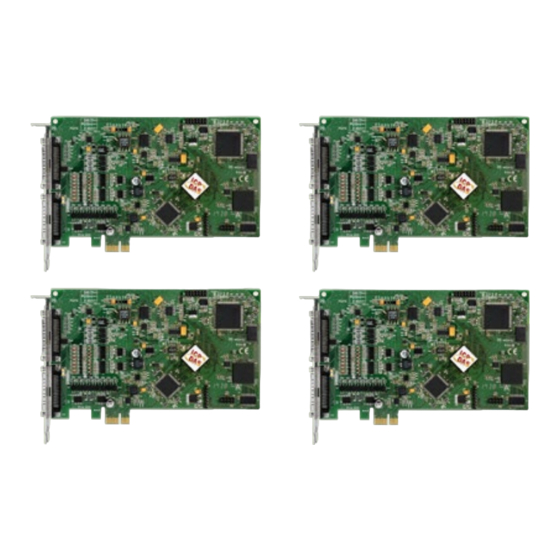
High-speed Multifunction Boards 2 Hardware Configuration 2.1 Board Layout The following is an overview of the board layout for each of the PCIe-LM4 Series cards. PCI-AD64SU CON1 The Connector for Analog input and Analog Output. Refer to Section 2.8 Pin Assignments User Manual, Ver. -
Page 10: Card Id Switch (Sw1)
High-speed Multifunction Boards 2.2 Card ID Switch (SW1) The PCI-AD64SU includes an onboard Card ID switch (SW1) that enables the board to be recognized via software if two or more PCI-AD64SU boards are installed in the same computer. The default Card ID is 0x0. -
Page 11: System Block Diagram
High-speed Multifunction Boards 2.3 System Block Diagram The following is the block diagram for the PCIe-LM4: User Manual, Ver. 1.0, May 2021, PMH-033-10 Page 11... -
Page 12: Analog Input
High-speed Multifunction Boards 2.4 Analog Input 2.4.1 Analog Input Range Input Range refers to the set of input voltages that an Analog Input channel can digitize with the specified accuracy. The PGA amplifies or attenuates the AI signal depending on the input range. User can individually program the input range of all channels on PCI-A64SU board. -
Page 13: Connecting Analog Input Signals
High-speed Multifunction Boards 2.4.2 Connecting Analog Input Signals The PCIe-LM4 Series board can be used to measure differential type Analog Input signals for floating signal source. AI CH 0 HI PCIe-LM4 Floating Signal Source AI CH 0 LO 100 kΩ ~ 10 MΩ A.GND AI CH n HI Floating... -
Page 14: Analog Input Data Acquisition Methods
High-speed Multifunction Boards 2.4.4 Analog Input Data Acquisition Methods The following is an overview of the five trigger modes: Trigger Mode Description No trigger signal is used and all A/D operations are initiated by software. Software Trigger After the clock signal is generated, A/D data will be recorded and saved to the buffer or the FIFO. Two clock sources are provided, a software command and a pacer clock. -
Page 15: Pin Assignments
High-speed Multifunction Boards 2.5 Pin Assignments 2.5.1 CON1 Connector of the PCI-AD64SU User Manual, Ver. 1.0, May 2021, PMH-033-10 Page 15... -
Page 16: I/O Connector Signal Descriptions
High-speed Multifunction Boards 2.5.2 I/O Connector Signal Descriptions Signal Name Reference Direction Description Analog Input channels 0 to 31. For Differential AI<0..31>+ AI<0..31>- Input measurements for general purpose analog inputs. Analog Input channels 0 to 63. For Single-Ended AI<0..63>+ AGND Input measurements for general purpose analog inputs. -
Page 17: Hardware Installation
High-speed Multifunction Boards 3 Hardware Installation Note: It is recommended that the driver is installed before installing the hardware as the computer may need to be restarted once the driver is installed in certain operating systems, such as Windows 2000 or Windows XP, etc. - Page 18 High-speed Multifunction Boards Step 3: Shut down and switch off the power to the computer, and then disconnect the power supply. Step 4: Remove the cover from the computer. Step 5: Select a vacant PCI slot. User Manual, Ver. 1.0, May 2021, PMH-033-10 Page 18...
- Page 19 High-speed Multifunction Boards Step 6: Unscrew and remove the PCI slot cover from the computer case. Step 7: Remove the connector cover from the I/O board. Step 8: Carefully insert the I/O board into the PCI slot by gently pushing down on both sides of the card until it slides into the PCI connector.
- Page 20 High-speed Multifunction Boards Step 9: Confirm that the card is correctly inserted in the motherboard, and then secure the PCIe-LM4 board in place using the retaining screw that was removed in Step 6. Step 10: Replace the covers on the computer.
-
Page 21: Software Installation
High-speed Multifunction Boards 4 Software Installation This chapter provides a detailed description of the process for installing the driver for the PCI-AD64SU Series board as well as how to verify whether the PCIe-862x Series board was properly installed. PCI-AD64su Series cards can be used on DOS, Linux and Windows 2000 and 32/64-bit versions of Windows XP/2003/2008/7/8 based systems, and the drivers are fully Plug and Play compliant for easy installation. - Page 22 High-speed Multifunction Boards Step 3: On the “Information” screen, verify that the DAQ card is included in the list of supported devices, then click the “Next>” button. Step 4: On the “Select Destination Location” screen, click the “Next>” button to install the software in the default folder, C:\ICPDAS\UniDAQ.
-
Page 23: Plug And Play Driver Installation
High-speed Multifunction Boards Plug and Play Driver Installation Step 1: Correctly shut down and power off your computer and disconnect the power supply, and then install the PCIe-LM4 Series board into the computer. For detailed information about the hardware installation of the PCI-AD64SU Series board, refer to Chapter 3 Hardware Installation. - Page 24 High-speed Multifunction Boards Step 4: Click the “Finish” button. Step 5: Windows pops up “Found New Hardware” dialog box again. User Manual, Ver. 1.0, May 2021, PMH-033-10 Page 24...
-
Page 25: Verifying The Installation
High-speed Multifunction Boards Verifying the Installation To verify that the driver was correctly installed, use the Windows Device Manager to view and update the device drivers installed on the computer, and to ensure that the hardware is operating correctly. The following is a description of how access the Device Manager in each of the major versions of Windows. - Page 26 High-speed Multifunction Boards Windows Server 2003 Step 1: “Start” button and point to “Administrative Tools”, and then click the “Computer Click the Management” option. Step 2: “System Tools” item in the console tree, and then click “Device Manager”. Expand the ...
- Page 27 High-speed Multifunction Boards Windows 8 Step 1: To display the Start screen icon from the desktop view, hover the mouse cursor over the bottom-left corner of screen. Step 2: Right-click the Start screen icon and then click “Device Manager”. Alternatively, press [Windows Key] +[X] to open the Start Menu, and then select Device Manager from the options list.
-
Page 28: Check The Installation
High-speed Multifunction Boards 4.3.2 Check the Installation Check that the PCIe-LM4 Series board is correctly listed in the Device Manager, as illustrated below. Installation successful User Manual, Ver. 1.0, May 2021, PMH-033-10 Page 28... -
Page 29: Calibration
High-speed Multifunction Boards 5 Calibration Introduction When shipped from the factory, the PCI-AD64SU Series board is already fully calibrated, including the calibration coefficients that are stored in the onboard EEPROM. For a more precise application of voltages in the field, the procedure described below provides a method that allows the board installed in a specific system to be calibrated so that the correct voltages can be achieved for the field connection. -
Page 30: Step-By-Step Calibration Process
Calibration Program for the PCI-AD64SU, which can be downloaded form: https://www.icpdas.com/en/product/PCI-AD64SU 5.2.1 PCIe-LM4 Calibration Step Step 1: Select calibration board (1) Select “0 PCI-AD64” from the “Select Calibration Board” drop-down menu. (2) Click the “RELOAD” button. User Manual, Ver. 1.0, May 2021, PMH-033-10 Page 30... - Page 31 High-speed Multifunction Boards Step 2: Calibrate the Analog Input Channel 0 to 9.9V (1) Connect 9.9 V voltage source to PCI-AD64SU.CON1.AI0 (Pin68) (2) Connect GND source to PCI-AD64SU.CON1.AGND (Pin60) (3) Click “Read” button to get hexadecimal value Step 3: Calibrate the Analog Input Channel 0 to 0V (1) Connect 0 V voltage source to PCI-AD64SU.CON1.AI0 (Pin68) (2) Connect GND source to PCI-AD64SU.CON1.AGND (Pin60) (3) Click “Read”...
- Page 32 High-speed Multifunction Boards Step 4: Calibrate the Analog Input Channel 0 to 4.9V (1) Connect 4.9 V voltage source to PCI-AD64SU.CON1.AI0 (Pin68) (2) Connect GND source to PCI-AD64SU.CON1.AGND (Pin60) (3) Click “Read” button to get hexadecimal value Step 5: Calibrate the Analog Input Channel 0 to 0V (1) Connect 0 V voltage source to PCI-AD64SU.CON1.AI0 (Pin68) (2) Connect GND source to PCI-AD64SU.CON1.AGND (Pin60) (3) Click “Read”...
- Page 33 High-speed Multifunction Boards Step 6: Calibrate the Analog Input Channel 0 to 2.49V (1) Connect 2.49 V voltage source to PCI-AD64SU.CON1.AI0 (Pin68) (2) Connect GND source to PCI-AD64SU.CON1.AGND (Pin60) (3) Click “Read” button to get hexadecimal value Step 7: Calibrate the Analog Input Channel 0 to 0V (1) Connect 0 V voltage source to PCI-AD64SU.CON1.AI0 (Pin68) (2) Connect GND source to PCI-AD64SU.CON1.AGND (Pin60) (3) Click “Read”...
-
Page 34: Windows Api Function
High-speed Multifunction Boards 6 Windows API Function For more details regarding the Windows API Functions for the PCI-AD64SU Series board, refer to UniDAQ SDK User manual, which can be downloaded from: http://www.icpdas.com/en/download/index.php?model=PCI-AD64SU User Manual, Ver. 1.0, May 2021, PMH-033-10 Page 34... -
Page 35: Appendix A: Daughter Boards
High-speed Multifunction Boards Appendix A: Daughter Boards DN-68A The DN-68A is a general-purpose DIN-Rail mountable daughter board containing female 68 pin D-sub I/O Connectors and is designed to allow easy field wiring connections. 68-Pin DN-68 PCI-AD64SU Pins 01 to 68 on the DN-68A daughter board are connected to the CON1 connector on the PCI-AD64SU using a 68-pin male-male cable. - Page 36 High-speed Multifunction Boards Appendix B: Revision history This chapter provides revision history information to this document. The table below shows the revision history. Revision Date Description 2021.05.18 Initial issue User Manual, Ver. 1.0, May 2021, PMH-033-10 Page 36...
Need help?
Do you have a question about the PCI-AD64 and is the answer not in the manual?
Questions and answers