Table of Contents

Subscribe to Our Youtube Channel
Related Manuals for Eastey ET2008


Summary of Contents for Eastey ET2008
- Page 1 ET2008, ET2012, ET2016, ET2020, ET2408, ET2412, ET2416, ET2420, ET3608, ET3612, ET3616, ET3620, ET4808, ET4812, ET4816, ET4820, ET5608, ET5612, ET5616, ET5620, ET7008, ET7012, ET7016, and ET7020 Professional Series Shrink Tunnels User Guide...
- Page 3 ET2008, ET2012, ET2016, ET2020, ET2408, ET2412, ET2416, ET2420, ET3608, ET3612, ET3616, ET3620, ET4808, ET4812, ET4816, ET4820, ET5608, ET5612, ET5616, ET5620, ET7008, ET7012, ET7016, and ET7020 Professional Series Shrink Tunnels User Guide Revised 08/11/2015 PN ET001000 Rev A Copyright and Trademarks Copyright ©2015 Eastey Enterprises, Inc.
-
Page 5: Table Of Contents
Contents Safety ..........................7 General Safety Precautions ..................7 Introduction ........................9 General System Description ..................9 Specifications ......................10 Dimensions ......................... 13 Unpacking ........................14 Installation ........................15 Location Requirements ....................16 Operation ........................17 Control Panel ......................17 Controls ........................ -
Page 7: Safety
Read this manual carefully and make it available to everyone connected with the supervision, maintenance, or operation of this machine. Additional copies are available on request (Eastey.com/contact-us). The development of a good safety program that is rigidly enforced is absolutely imperative when involved in the operation of industrial equipment. - Page 8 • Do not make any modifications to either the electrical circuitry or the mechanical assemblies of this machinery. Such modifications may introduce hazards that would not otherwise be associated with this machinery. Eastey Corporation will not be responsible for any consequences resulting from such unauthorized modification. Do not operate a machine if any modification has been made •...
-
Page 9: Introduction
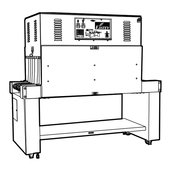
Introduction 9 Introduction General System Description Vent Control Panel Vent slots slots Side Vent Heat Control Shield Knob (Pre-2015) Shrink Shrink Tunnel Tunnel Entrance Exit Conveyor Conveyor Idler End Drive End Frame Casters Leveling Legs... -
Page 10: Specifications
Model Machine Dimensions Chamber Dimensions Conveyor Conveyor Number Width (A) Height (B) Length (C) Width Height Length Width Length ET2008 – 33 in. 56-72 in. 74 in. 20 in. 4-20 in. 52 in. 20 in. 72 in. ET2020 84 cm... - Page 11 Introduction 11 Explanation of Model Numbers • E = Manufactured by Eastey Enterprises Inc., division of Engage Technologies. • T = Tunnel; machine is a Professional Series Shrink Tunnel. • _ _ = 20, 24, 36, 48, 56, or 70 — First two digits indicate the nominal chamber width or width of the conveyor belt in inches: 20, 24, 36, 48, 56, or 70 inch conveyor widths are available.
- Page 12 • Leveling legs provide sturdy base once in place • Custom two-part epoxy finish resists scratching • Stainless steel models available on ET2008, ET2012, ET2016, and ET2020 • 220V three-phase power input standard, some models optionally available for 220V single-phase or 480 three-phase power input •...
-
Page 13: Dimensions
Introduction 13 Dimensions See the table on page 10 (Machine Dimensions in Specifications table) for overall machine dimensions of width, height, and length. Height Conveyor Height 35.5 in. Approx. Width Length Front View Side View (Sketches not to scale.) -
Page 14: Unpacking
We are willing to assist you in every reasonable manner to help you collect claims for loss or damage. However, this willingness on Eastey’s part does not make Eastey or its parent or related companies responsible for collections or claims or replacement of... -
Page 15: Installation
Installation 15 Installation Lift the machine up and off of the shipping pallet. CAUTION! ET Professional Series Shrink Tunnels are heavy and may require a forklift, floor crane, or several people to move the machine safely. Use proper equipment when lifting the shrink tunnel and ensure it is secure and will not shift while being moved off the shipping pallet. -
Page 16: Location Requirements
16 Installation Location Requirements When installing the shrink tunnel please be aware of the following considerations: 1. The surface on which it is located is flat and level. 2. Conveyor or packing table height. 3. Alignment with packaging line. When the shrink tunnel is positioned in the operating location you will need access to the control panel. -
Page 17: Operation
Operation 17 Operation Control Panel The control panel is located, centered near the top on one side of the tunnel. Control panel design for ET Professional Series Shrink Tunnels was enhanced to provide a blower motor speed control in 2015. For a comparison of the current control panel layout since 2015 and the control panel layout for units built pre-2015, see the following illustrations. -
Page 18: Controls
18 Operation Controls 1. Power On-Off Switch — The power on/off switch located in the upper left corner of the electrical POWER ON HEATER BANK ENCHUFE EN BANCO de CALENTADORA panel turns the power off or on for the ET Professional Series Shrink Tunnel. -
Page 19: Sequence Of Operation
Operation 19 Sequence of Operation 1. Turn on power to the shrink tunnel by toggling the Power switch in the upper left corner of the control panel to the On position. (The temperature in the tunnel will be displayed on the temperature control.) 2. -
Page 20: Adjustments
20 Adjustments Adjustments Temperature Controller Settings (ETC00011) 1. PV = Processing value (red in color). 2. SV = Setting value (green in color). 3. Back ( ), forward ( ), down ( ), and up ( ) keys. 4. Programming key access door — Open to access programming keys. 5. -
Page 21: To Change The Set Value
Adjustments 21 To Change the Set Value 1. Press the left-arrow ( ) button and a digit will begin to flash. The flashing digit indicates the digit whose value can be changed by pressing the down- ( ) or up- arrow ( ) buttons. - Page 22 22 Adjustments Factory settings are as follows: SV (Set Value, your set point) is set to 400°. AL-1 is set to 250° 400° - 250° = 150° To set AL-1 so the machine will shut down at 150°, press the left-arrow key and the right-most digit will flash.
-
Page 23: Maintenance
Maintenance 23 Maintenance To aid in the high reliability of the shrink tunnel, inspect the machine regularly and perform maintenance as required. Disconnect electrical power before making any repairs. Be very careful when servicing or adjusting this equipment. If in doubt, stop and obtain qualified help before proceeding. -
Page 24: Preventative Maintenance For Modular Plastic Conveyor Belts
24 Maintenance Check for loose fasteners. Tighten as necessary. Check the condition of the power cord for wear, especially if it is exposed to traffic. Check that the tunnel is able to maintain the set temperatures. If not, refer to the Adjustments Section of this User Guide for instruction. -
Page 25: Conveyor Belt Tension Adjustment
Maintenance 25 When performing repairs to the conveyor, it is important to remove or protect the belt to avoid damage from welding sparks or from other tools. Avoid using the belt for uses other than for what it was specified. If you need to utilize the belt in a different application, consult the manufacturer first. - Page 26 26 Maintenance 4. Clean all rollers using steel wool or a wire wheel. Make sure all rollers are smooth and free of residue and burrs. 5. Fit the new silicone rubber tubing onto each roller and work on by hand at least ½...
-
Page 27: Replacing Tunnel Components
Maintenance 27 Replacing Tunnel Components Caution! Disconnect main power source before performing any procedure to replace any tunnel component(s). Fuse replacement or electrical component replacement Major electrical components, except the conveyor motor (whose replacement procedure is provided on the previous page) and the heater bank and blower motor (whose replacement procedures are provided separately below), are located behind the fold- down electrical control panel for easy maintenance. - Page 28 28 Maintenance For the second option (to replace entire controller and receptacle), first take note of wire locations (make a sketch and label the wires with tape, if necessary), and then disconnect wires from the temperature controller and thermocouple. Slide the controller and receptacle out of the front of the panel.
-
Page 29: Plastic Belt Assembly And Disassembly
Maintenance 29 and replace the motor. Rotation on the blower motor needs to be counter-clockwise as viewed from the electrical inlet and hub side. Reassemble the new motor and blower wheel housing and reassemble components in the same manner in which they were disassembled. - Page 30 30 Maintenance Bottom Metal disks view To assemble the belt 1. Bring ends of the belt together, and aligning holes, insert metal rod through holes for the entire width of the belt. 2. Insert a plastic retainer clip into place to retain the metal rod. Use a hammer, if necessary, to gently tap the retainer clip into place.
- Page 31 Maintenance 31 To disassemble the belt 1. Place a block under the belt and place the belt upside-down over the block, so the link to be opened is positioned close to the block. 2. Use a screwdriver to push down on the retainer clip to unseat it. 3.
-
Page 32: Wire Belt Repair Splicing
32 Maintenance Wire Belt Repair Splicing Caution! Disconnect main power to the conveyor before attempting to repair or adjust belt. Before you begin splicing • Release all belt tensioning mechanisms • If installing a new belt, thread the belt onto the conveyor - Check to be sure that the smooth side is “up”... - Page 33 Maintenance 33 Far Edge Near Edge 5. Insert the strand ends into the center space of the opposite edge. (Space 3 in the illustration below.) 6. Pull the ends of the strand through until the center section “pops” or “locks” into place.
- Page 34 34 Maintenance Step 2 – Weave the strand to one side 1. Bend one end of the wire up and insert it around the z-bend in the next space on the edge of the wire closest to you. (Space 5 in the following illustration.) Always try to avoid bending the wire in the z-bend.
- Page 35 Maintenance 35 Step 3 – Weave the strand to the other side 1. Repeat the steps in Step 2, going in the opposite direction, weaving to the other side edge of the belt as shown in the following illustrations. 2. If you are installing a new belt, you are finished splicing. Step 4 –...
- Page 36 36 Maintenance Step 5 – Check Entire Belt Circuit • Z-bends should not come into contact with any conveyor component (including end rolls, wear strips, transfer support rails, nose bars, etc.) • Adjust as needed. Step 6 – Adjust Tension •...
-
Page 37: Troubleshooting
Troubleshooting 37 Troubleshooting The following illustration shows the D.C. board used in the shrink tunnel. Some of the solutions to problems identified in the troubleshooting table that follows refer to adjustments made by tuning potentiometers on this board. Basic KBMM™ Controller Board Connection Diagram KBMM™... - Page 38 38 Troubleshooting Problem Solution Conveyor not moving 1. The conveyor motor is controlled by a D.C. control board. Input is 220 VAC in and variable 0 to 90 VDC out. 2. Is a green light on? If not, check the input fuse. 3.
- Page 39 Troubleshooting 39 Problem Solution No air flow 1. Check AC Inverter adjustable speed pot settings below. • C.L.: Set at approximately 12 o’clock. • Max.: All the way counter-clockwise. • Min.: All the way clockwise. • ACC.: All the way clockwise. •...
- Page 40 40 Troubleshooting Color and Color and Flash Sequence After Drive Status Sequence Flash Rate Recovered Fault Normal Operation (Run) Green 1 sec. On / Off — Overload (120% – 160% Full On continuously Green Load t (Drive Timed Out) 0.25 sec. On / Off —...
- Page 41 Troubleshooting 41 Problem Solution No heat 1. Is the display on the temperature controller on? If not, check for 220 Volts on terminals 9 and 10. If there voltage, replace temperature controller. 2. If the display is on and SV is set higher than PV, is there a red light on? If not, replace the thermocouple.
- Page 42 42 Troubleshooting Menu 2 Temperature Controller 1 Temperature Controller 2 Su-2 Su-2 (same as 1) AL-2 (same as 1) AHYS - AHYS - (same as 1) (same as 1) (same as 1) (same as 1) IN-B IN-B (same as 1) REST - REST - (same as 1)
-
Page 43: Parts List
Parts List 43 Parts List Electrical Eastey Bundling Shrink Tunnel Part No. Description... - Page 44 44 Parts List Part No. Description...
-
Page 45: Mechanical
Parts List 45 Mechanical Hood Parts Part No. Description... - Page 46 46 Parts List Conveyor Parts Part No. Description...
- Page 47 Parts List 47 Part No. Description...
- Page 48 48 Parts List...
-
Page 49: Appendix A: Electrical Schematics
Appendix A: Electrical Schematic 49 Appendix A: Electrical Schematics Panel Layout Panel layout for tunnels manufactured in 2015 and forward. HEATER POWER BANK DC CONTROL BLOWER CONVEYOR SPEED SPEED CONTROL CONTROL Panel layout for tunnels manufactured before 2015 POWER HEATER BANK DC CONTROL SPEED... - Page 50 50 Appendix A: Electrical Schematic Motor Controller Board (KBMM™) Basic Connections for Controller Board and Barrier Terminal Kit Basic KBMM™ Connection Diagram KBMM™ with Barrier Terminal Kit CONTROL LAYOUT & GENERAL CONNECTION DIAGRAM (Model KBMM-225D Shown) (Note: Control is set for 208 /230 VAC line input, 0 -180 VDC output with armature feedback) Plug-In Horsepower Resistor ®...
-
Page 51: Electrical Schematic, 480 Volt
Appendix A: Electrical Schematic 51 Electrical Schematic, 480 Volt 480 VOLTS 15/30 480V F4/ 15 AMP F5/ 15 AMP 220V TEMP CONTROLLER PIN-10 PIN-9 CR3–1 TT1–1 PIN–7 PIN–6 HEATER BANK CR1-4 CR1-5 ON OFF CONTROL RELAY ON OFF PIN–13 PIN–14 MAIN BLOWER MOTOR DELAY... -
Page 52: Electrical Schematic, 220 Volt
52 Appendix A: Electrical Schematic Electrical Schematic, 220 Volt GROUND 220 VAC 50/60 AMP POWER ON/OFF CR3–1 TEMP CONTROLLER PIN–10 PIN–9 PIN–7 PIN–6 HEATER BANK F5 / 15 AMP F4 / 15 AMP ON OFF CONTROL RELAY PIN–13 PIN–14 MAIN BLOWER MOTOR F12,13,14 / 4 AMP DELAY... - Page 53 Appendix A: Electrical Schematic 53...
-
Page 54: Warranty Statement
ET Professional Series Shrink Tunnels Warranty Statement Eastey Enterprises warrants that all of the products it ships will be in good working order and free from defects in material and workmanship for a period of two (2) years from the date of shipment by Eastey and will conform to the published specifications for that product. - Page 55 LIABLE FOR ANY SPECIAL, CONSEQUENTIAL, INDIRECT OR SIMILAR DAMAGES, INCLUDING LOST PROFIT OR LOST OPPORTUNITIES OF ANY TYPE ARISING OUT OF THE USE OR INABILITY TO USE THESE PRODUCTS EVEN IF EASTEY ENTERPRISES, INC. HAS BEEN ADVISED OF THE POSSIBILITY OF SUCH...
-
Page 56: Customer Support
Eastey Technical Service at one of the numbers listed below. Toll-Free Phone 800-835-9344 Phone 763-428-4846 763-795-8867 E-mail info@eastey.com www.eastey.com Thank you again for your purchase of Eastey products. We are pleased to be a part of your packaging needs.
Need help?
Do you have a question about the ET2008 and is the answer not in the manual?
Questions and answers