Table of Contents
Advertisement
Quick Links
Advertisement
Table of Contents

Subscribe to Our Youtube Channel
Related Manuals for Eastey SB-2 EX-Auto


Summary of Contents for Eastey SB-2 EX-Auto
- Page 1 SB-2/3EX-Auto Automatic Carton Sealing Machine User Guide...
- Page 3 Copyright and Trademarks Copyright ©2012-2021 Engage Technologies Corporation All rights reserved. All trademarks and brand names are the property of their respective owners. Eastey 7041 Boone Ave. N. Brooklyn Park, MN 55428 Phone: (763) 428-4846; Fax (763) 795-8867; 1-800-853-9344 www.eastey.com...
-
Page 5: Table Of Contents
Contents Safety ..........................7 Explanation of Symbols ....................8 Introduction ........................9 SB-2/3EX-Auto Case Taper Overview ................9 Specifications ......................10 Dimensions ......................... 11 Installation ........................13 Location Requirements ....................14 Optional Entrance and Exit Roller Tables..............15 Next Steps........................15 Loading the Tape Cartridges .................. -
Page 7: Safety
Safety 7 Safety Safety Precautions Before installing, operating, or servicing this equipment, please read the following precautions carefully: • This machine is equipped with moving belts. Do not place hands near the belts when they are moving as fingers may be pinched where belts enter the frame. We suggest the use of a roller-type exit conveyor or pack table for your cases. -
Page 8: Explanation Of Symbols
8 Safety Explanation of Symbols Caution sign or Safety Alert symbol. Indicates caution, be alert, Your safety is involved. Knowledge of safe operation is required. Caution indicates a hazardous situation which, if not avoided, could result in minor or moderate injury or damage to equipment or surroundings. -
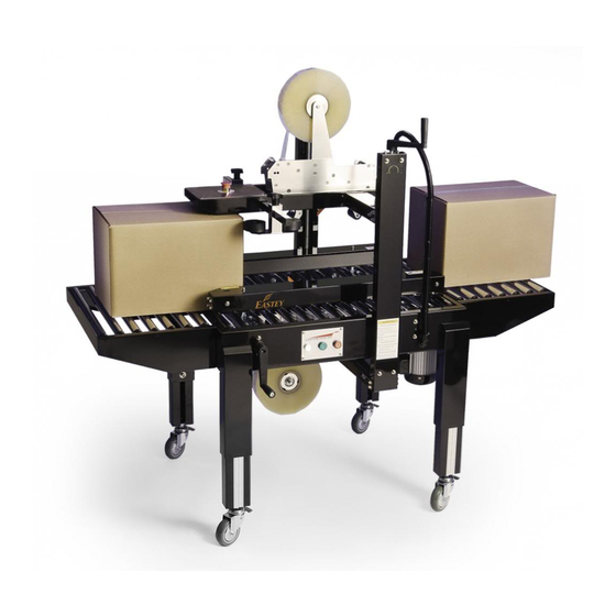
Page 9: Introduction
Introduction 9 Introduction SB-2/3EX-Auto Case Taper Overview Height Upper Tape Adjustment Head Seat Crank Vertical Column Rear Flap Folding Assembly Lower Tape Head Seat Drive Belt Emergency Stop Switch (E-Stop) Control Panel with Start/Run and Stop buttons Width Adjustment Crank Electrical Adjustable Main Power... -
Page 10: Specifications
10 Introduction Specifications Model SB-2/3EX-AUTO Tape 1.5 inches or 2 inches Belt speed 75ft/min (L) 4.7 to 24 inches Capacity (W) 4.3 to 19.5 inches (H) 4.7 to 19 inches~500mm Consumption 450W Machine size (L) 77 inches (W) 35.5 inches (H) 67 inches Machine net weight 660 lbs. -
Page 11: Dimensions
Introduction 11 Dimensions Dimensions shown in inches (and centimeters). 35 in. 24.8 in. (90 cm) (63 cm) 30 in. (76 cm) 77 in. (196 cm) 65 in. Floor to Top of (185 cm) Column Max. 27 in. to 34.5 in. (68 cm to 88 cm) Conveyor Roller... - Page 12 12 Introduction SB-2/3EX-Auto Case Taper is shown below with optional roller tables at infeed and exit ends, and optional guards with door and windows, and optional alarm light stack. 35 in. 33.5 in. 24.8 in. (90 cm) (85 cm) (63 cm) 30 in.
-
Page 13: Installation
Installation 13 Installation Carefully unpack the outer carton Avoid damaging the machine body. Remove the shipping bolts that secure the carton sealer to the shipping pallet. Lift the carton sealer of the pallet. CAUTION! The SB-2/3EX-Automatic Carton Sealer is very heavy and will require a forklift, floor crane, or several people to move safely off the shipping pallet. -
Page 14: Location Requirements
14 Installation Location Requirements Move the case taper to the desired location. To lift or move the case taper without casters installed, you will need to use a pallet jack or forklift to lift and move it. If you have installed the casters, release the brake lever on each of the locking casters to move the taper easily over a smooth flat surface. -
Page 15: Optional Entrance And Exit Roller Tables
Installation 15 Optional Entrance and Exit Roller Tables The optional infeed and exit roller tables available for the case taper are identical and therefore interchangeable. If they have not been installed from the supplier or have been removed for shipping, install them as follows. 1. -
Page 16: Loading The Tape Cartridges
16 Operation Loading the Tape Cartridges Turn the main power switch to “Off” and disconnect the power. CAUTION! To avoid personal injury, remove the tape cartridge before loading tape. When handling the tape cartridge be careful to avoid contact with the tape cutting blade. After the taping cartridge has been removed push the tape roll onto the tape core assembly. -
Page 17: Check Tension
Tape Head User Guide provided with the tape head. For convenience, diagrams for threading tape in the Eastey-EX Tape Head and EZ-EX Tape Head are provided on the following page. Follow the diagram that applies for your... - Page 18 18 Operation Eastey-EX Tape Head Adhesive Side Adhesive Side Upper Cartridge Bottom Cartridge EZ-EX Tape Head Adhesive Side Adhesive Side Upper Cartridge Bottom Cartridge...
-
Page 19: Main Spring Adjustment
Operation 19 Center Tape — Eastey-EX Tape Head only Make sure the tape is centered on all the rollers. There are several rollers in the tape cartridge where the tape alignment should be checked to verify the tape stays on center as it is being dispensed. -
Page 20: Power
20 Operation To Lessen Spring Tension 1. First loosen the outer nut away from the top crossmember. 2. Follow this by turning the inner nut to adjust it outward, lessening tension on the spring. 3. When the desired tension is achieved, re-tighten the inner nut against the crossmember to jam the assembly and lock the position. -
Page 21: Control Panel
Operation 21 Main Power Switch Control Panel Stop Power Emergency Start / (Red) Indicator Stop (White) (Green) Power Indicator Lamp (White) • On when carton sealer is in operation. • Off when carton sealer is not in operation. Start / Run Button (Green) Press the Start button to start motors and belts. -
Page 22: Adjustments
22 Adjustments Adjustments Air Pressure unit The air pressure is pre-set at the factory to 80 PSI. The air pressure can be changed up or down for specific requirements. Make air pressure changes are made in small increments. Inspect periodically to make sure the drain system is functional and properly lubricated. Air Pressure Pressure Adjustment Knob... -
Page 23: Height And Width Adjustment
Adjustments 23 Height and Width Adjustment With the power off, place an appropriate size carton in the Case Sealer. Use the drive belt width adjustment crank to set the drive belt width to the correct box width. Set Screw Drive Belt Width Adjustment Crank Use the height adjustment crank to set the upper tape head to the correct box height. -
Page 24: Top Squeezer Roller Width Adjustment
24 Adjustments Top Squeezer Roller Width Adjustment Loosen the locking knobs on the top squeezer alignment rollers to set the top width to the correct box width and re-tighten the locking knobs. This will ensure the box stays centered. Locking Knobs Squeezer Rollers... - Page 25 Adjustments 25 Side flaps will be closed while carton is moving forward and reaches the 2 closing arms. The most ideal angles for the 2 closing bars are 30 degrees in width. The closing arms are set to an angle of 15 degrees incline (note: The arms are moveable and adjustable in 2 ways both height &...
-
Page 26: Rear Flap Closer Speed Adjustment
26 Adjustments Rear Flap Closer Speed Adjustment There are two small air valve knobs used to adjust the speed of the rear flap closing arm. One knob will adjust the down speed and the other is for the retraction speed. The rear closing arm pressure is pre-set at the factory. -
Page 27: Machine Body Height Adjustment
Adjustments 27 Machine Body Height Adjustment To adjust the leg height, loosen the screws on each leg and slide the insert up or down. When the leg is at the desired height, retighten the adjustment screws to secure the leg height. -
Page 28: Maintenance
28 Maintenance Maintenance The SB-2/3EX-Automatic Industrial Case Taping System will provide many hours of maintenance free operation. There are a few items that may require attention from time to time. Rollers Make sure rollers stay clean and grease free. If you should have to clean the rollers simply wipe them down with a clean lint free cloth. -
Page 29: Troubleshooting
Troubleshooting 29 Troubleshooting Problem POSSIBILITIES Solution If machine is not The air pressure may not Adjust the air operating. be sufficient. Pressure. If the air cylinder on the Kinked hoses and/or Reposition the hoses & flap closing system does wiring. wiring. -
Page 30: Parts List
30 Illustrated Parts List Parts List Electrical... - Page 31 Illustrated Parts List 31 ITEM PART NO. DESCRIPTION REFERENCE Q’TY SEPARATED POWER → ON/OFF P0311-020000700 5001873 (5001873 includes items 1, 2 & 2) 71710001-01...
- Page 32 32 Illustrated Parts List ITEM PART NO. DESCRIPTION REFERENCE Q’TY 5005266 LINE SHANK 71710001-02 5005267 LINE SHANK UNITS 71710001-03 5005268 TERMINAL BLOCKS TB6P 70560601 5005269 POWER SUPPLY RS-25-24 P0307-010001100 5001916 POWER SUPPLY NES-35-24 72810005 5005270 CIRCUIT BREAKER IK60N2PC16A P0305-010001100 5001705 POWER FUSE C60A2PC16A (FUSE 10A GL) 72571601 5005271...
-
Page 33: Pneumatic Parts
Illustrated Parts List 33 Pneumatic Parts... - Page 34 34 Illustrated Parts List ITEM PART NO. DESCRIPTION REFERENCE Q’TY 5005282 AIR F.R.L UNITS (MAFR300L-8A-D) P405-0000110 5001820 81110002 5001820-1 CCNNECTOR (PL8-02) 81060105 5001995 CCNNECTOR MPP-20 81060100 5001820-2 PRESSURE GAUGE 81040001-1 5001734 SOLENOID VALVE 81090001 5002101 BRASS SILENCER 81100101 5001996 CCNNECTOR (PC8-02) 81060120 5005283 PLUG (1/4”)
-
Page 35: Side Belts
Illustrated Parts List 35 Side Belts... - Page 36 36 Illustrated Parts List ITEM PART NO. DESCRIPTION REFERENCE Q’TY 5005288 BELT COVER KA110887L0 5005256 SCREW M6*12L 10250612 5001030 BELT (SET)-SB2/3EX-AUTO CE300500 5001715 PULLEY DRIVER CA301900 5001711 MOTOR SHAFT CA30250A 5001701 BEARING 6203 30302031 5001757 MOTOR SEAT CA302900 5001700 BEARING 6003ZZ 30300030 5001712 UNIVERSAL JOINT...
- Page 37 Illustrated Parts List 37 ITEM PART NO. DESCRIPTION REFERENCE Q’TY 5005293 HANDLE CRANK ARM P1112-0000-60A 5001710 CA201500 5001977 HANDLE RING CA303200 5002153 SPINDLE WIDTH ADJUSTMENT CA300700 5001854 CHAIN SPPOCKET 12T CA302200 5005294 BELT COVER KA110887R0 5001753 GUIDE PLATE CA3010R0 5005295 SUPPORT COLUMN CE3002R0 5001713...
-
Page 38: Vertical Column With Height Adjustment
38 Illustrated Parts List Vertical Column with Height Adjustment... - Page 39 Illustrated Parts List 39 ITEM PART NO. DESCRIPTION REFERENCE Q’TY 5005305 COLUMN COVER FRAME KA11109200 5005306 FIX SEAT KA11109000 5001921 SHAFT SEAT CA302000 5004083 COPPER RING CA200200-01 5005307 TOWER FRAME COVER KA11108800 5001853 GEAR (S45C) M=1.5, T=30 KA31003900 5005308 BEARING AXK1528 30361528 5004084 WASHER AS1528...
- Page 40 40 Illustrated Parts List ITEM PART NO. DESCRIPTION REFERENCE Q’TY 5001920 GEAR (POM) M=1.5, T=30 KA31005700 5005320 TRANSMISSION SHAFT KA03054000 5005321 COVER FRAME (TOP) KA11109600 5002111 BEARING 6002ZZ=NR(CWB) 3030002N 5005322 FIX SEAT KA11113100 2005323 C-RINGS-15 113001500 5005324 COVER FRAME KA11109500...
-
Page 41: Flap Guide And Upper Tape Head Seat Assembly
Illustrated Parts List 41 Flap Guide and Upper Tape Head Seat Assembly... - Page 42 42 Illustrated Parts List ITEM PART NO. DESCRIPTION REFERENCE Q’TY 5005325 SUPPORT BAR KA03065400 5005326 FOLDING DEVICE SEAT KA11084800 5005327 SUPPORT PLATE KA11085200 5005328 SUPPORT SEAT KA11086100 5005329 UPPER TAPE HEAD SEAT (LEFT) KA110853L0 5005330 CONNECT BAR KA03065600 5001696B B PLATE CA100300 5005331 UPPER TAPE HEAD SEAT (RIGHT)
- Page 43 Illustrated Parts List 43 ITEM PART NO. DESCRIPTION REFERENCE Q’TY 5001726 ROD END PHS12EC M12x1.25 81060002 5005345 ARM SHAFT KA03041900 5005346 FOLDING ARM SEAT KA11085600 5005347 C-RING S-15 11301500 5001725 BEARING 6002ZZ-NR(CWB) 3030002N 5005348 CYLINDER CONNECT SHAFT KA03041800 500349 FOLDING ARM KA11085700 5005350 FLAP DIVIDER SUPPORT...
-
Page 44: Machine Body
44 Illustrated Parts List Machine Body ITEM PART NO. DESCRIPTION REFERENCE Q’TY 5005357 MACHINE FRAME KA11087200 5005256 SCREW M6*12L 10250612 5005010 MACHINE LEG KA11087000 5005257 CLAMP KA11084000 5005258 FEXED PLATE KA11083900 5005011 ADJUSTABLE LEG KA11080900 5005299 NUTN 1/2” 10301201 5001912 CASTER KA04012600 5001707... - Page 45 Illustrated Parts List 45 ITEM PART NO. DESCRIPTION REFERENCE Q’TY 5001718 ROLLER(SHORT) CA302300 5004131 B-PLATE CA33070A 5004132 A-PLATE CA33060A 5005361 STABILIZER, LEG KA11087300 5005362 CE-2013-04 5005363 RADIOTUBE PLATE CC302700 5002200 LOCK PA201800-01 5002129 PA201800-02 5005364 PLATE PD400610...
-
Page 46: Optional Door
46 Illustrated Parts List Optional Door... - Page 47 Illustrated Parts List 47 ITEM PART NO. DESCRIPTION REFERENCE Q’TY 5005365 INFEED/OUTFEED TABLE FRAME CC430100 5001720 ROLLER ASSY. CA400200 5005366 INDEXOR SEAT (L) KA110878L0 5005367 INDEXOR SEAT (R) KA110878R0 5005368 INDEXOR SEAT KA11088200 5005369 BUSHING LFB-1010 31001012 5005370 INDEXOR SEAT SHAFT CC301900 5005371 U-SHAPE SLING BRACKET+SDB SHAFT M32...
- Page 48 48 Illustrated Parts List ITEM PART NO. DESCRIPTION REFERENCE Q’TY 5005391 HINGE (R) PD400520 5005392 HINGE (L) PD400520-L 5005393 MAGNET CE401000 5001706-1 PHOTO EYE SENSOR 7360CD02 5005394 PHOTO EYE SENSOR SUPPORT (INNER) KA11056010 5005395 PHOTO EYE SENSOR SUPPORT (OUTTER) KA11056110 5005396 SUPPORTING FIXED SEAT KA1106770...
-
Page 49: Appendix A: Electrical Schematic
Appendix A: Electrical Schematic 49 Appendix A: Electrical Schematic... - Page 50 50 Appendix A: Electrical Schematic Electrical Schematic Continued...
- Page 51 Appendix A: Electrical Schematic 51 Electrical Schematic Continued...
- Page 52 52 Appendix A: Electrical Schematic Electrical Schematic Continued...
- Page 53 Appendix A: Electrical Schematic 53 Electrical Schematic Continued...
- Page 54 54 Appendix A: Electrical Schematic Electrical Schematic Continued...
-
Page 55: Warranty Statement
Warranty Statement SB-2/3EX-Automatic Carton Sealing Machine Warranty Statement Eastey warrants that all of the products it ships will be in good working order and free from defects in material and workmanship and will conform to the published specifications for that product. - Page 56 ESSENTIAL PURPOSE, IN NO EVENT WILL EASTEY BE LIABLE FOR ANY SPECIAL, CONSEQUENTIAL, INDIRECT OR SIMILAR DAMAGES, INCLUDING LOST PROFIT OR LOST OPPORTUNITIES OF ANY TYPE ARISING OUT OF THE USE OR INABILITY TO USE THESE PRODUCTS EVEN IF EASTEY HAS BEEN ADVISED OF THE POSSIBILITY OF SUCH DAMAGES.
-
Page 57: Customer Support
For help setting up or operating the SB-2/3EX-AUTO Automatic Carton Sealer, please contact Eastey Technical Service at one of the numbers listed below. Toll-Free Phone 800-835-9344 Phone 763-428-4846 763-795-8867 E-mail info@eastey.com www.eastey.com Thanks again for your purchase of Eastey products. We are pleased to be a part of your packaging needs.
Need help?
Do you have a question about the SB-2 EX-Auto and is the answer not in the manual?
Questions and answers