Table of Contents
Advertisement
Quick Links
Advertisement
Table of Contents

Subscribe to Our Youtube Channel
Related Manuals for Eastey EXS-100


Summary of Contents for Eastey EXS-100
- Page 1 EXS-100 Eastey EXS-100 Semi-Automatic Strapping Machine User Guide...
- Page 3 EXS-100 Eastey EXS-100 Semi-Automatic Strapping Machine User Guide Revised 05/11/2020 P/N 5001699 Rev. A Copyright and Trademarks Copyright ©2020 Engage Technologies Corporation. All rights reserved. All trademarks and brand names are the property of their respective owners. Eastey 7041 Boone Ave. N.
-
Page 5: Table Of Contents
Contents Safety ..........................7 Explanation of Symbols ....................8 Introduction ........................9 EXS-100 Semi-Automatic Strapping Machine Overview ..........9 Specifications ......................10 Dimensions ......................... 11 Machine Serial Number ....................12 Typical Applications ....................12 Installation ........................13 Location Requirements ....................14 Assembling Stop Angle Brackets to Top Work Surface .......... - Page 6 Customer Support ....................... 52...
-
Page 7: Safety
Read this manual carefully and make it available to everyone connected with the supervision, maintenance, or operation of this machine. Additional copies are available on request (Eastey.com/contact-us). The development of a good safety program that is rigidly enforced is absolutely imperative when involved in the operation of industrial equipment. -
Page 8: Explanation Of Symbols
8 Safety Explanation of Symbols Caution sign or Safety Alert symbol. Indicates caution, be alert, Your safety is involved. Knowledge of safe operation is required. Ground symbol. Indicates ground. Use Class-3 (lower than 1000) cable to ground to earth. Incomplete grounding may lead to electrical shock. Electrical shock hazard. -
Page 9: Introduction
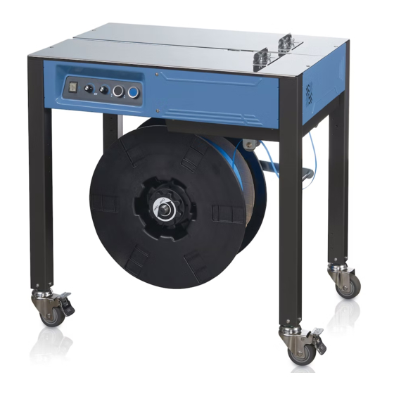
Introduction 9 Introduction EXS-100 Semi-Automatic Strapping Machine Overview Working Surface — Strap Slot — Allows Place Items To Be Strap To Pass Strapped Here Under Bottom Of Packages Package Stop Control Panel Angle With Brackets Operator Align Controls Packages To... -
Page 10: Specifications
10 Introduction Specifications Strap Width 0.2” – 0.6” (5mm - 15.5mm) Strap Thickness 0.02 – 0.027 (0.45mm – 0.7mm) Strap Coil Core Diameter 7.9” (200mm) Strap Coil Core Width 7.5” – 7.9” (190mm – 200mm) Strap Material Polypropylene only Minimum Package Size 2.75”... -
Page 11: Dimensions
Introduction 11 Dimensions Keep This Area Clear For Strapping 19.7 in. Machine (50cm) Operation And For Packages 19.7 in. (50cm) Keep This Area Clear For The Operator And For Spool Changeover 29.5 in. 19.7 in. (75cm) (50cm) 21.5 in. (54.6cm) 30.7 Overall Length Overall Width... -
Page 12: Machine Serial Number
Typical Applications Eastey EXS-100 Semi-Automatic Strapping Machine This plastic strapping machine can be used for a wide range of applications where the maximum package width is at least 2.75 inches (70mm) and the minimum height is 0.79 inches (20mm). -
Page 13: Installation
Installation 13 Installation Unpack the outer carton and shipping material carefully to avoid damaging the strapping machine. Remove shipping straps securing the strapping machine legs and casters to the molded shipping base and lift the strapping machine off the pallet. CAUTION! The strapping machine may require more than one person to move safely off the shipping base. -
Page 14: Location Requirements
Location Requirements When installing the Eastey EXS-100 Semi-Automatic Strapping Machine it is important to be aware of the following considerations: 1. The floor surface is flat and level where the strapping machine will be placed. -
Page 15: Assembling Stop Angle Brackets To Top Work Surface
Installation 15 2. Height of nearby packing equipment feeding into or receiving product from the strapping machine. The EXS-100 Semi-Automatic Strapping Machine is pre- configured to 30.7 in. (78cm) standard height. 3. Alignment with packaging line. 4. Allow for a clear area of approximately 19.7 inches (50mm) minimum from the front (operator’s side) for the length of the machine for the operator, and 20... -
Page 16: Loading The Strap Coil In The Spool And Routing The Strap
16 Installation Loading the Strap Coil in the Spool and Routing the Strap The strap threading procedure involves loading the dispenser spool and then routing the strap from the spool up and through the strapper machine body. 1. Rotate the hand nut (A) at the center of the spool hub counterclockwise to remove the nut from the spool shaft and set it aside. -
Page 17: Operation
Operation 17 Operation Main Control Panel Power Strap Feed Manual Reset On / Off Length Tension / Feed Switch Tightness Adjustment Adjustment The main control panel is located on the operator’s side of the strapping machine, just below the work surface and to the left end of the machine. Power On / Off Switch The Power On / Off switch turns power to the machine on or off. -
Page 18: Operating The Machine And Strapping Packages
18 Operation Manual Feed Use this button to manually feed strapping material. Strapping material will be fed out for as long as the button is pressed. Release the button to stop feeding material. Reset The Reset button allows you to reset the strapper, expelling the strapping material in the current job and cutting it off in order to begin with a freshly cut strap end. - Page 19 Operation 19 4. Place the strap around the package to be strapped, guiding the strapping material up and over the package so the strapping material makes an arch over and around the package CAUTION: Keep hands and fingers away from the inside of the arch made by the strapping material while the machine is operating.
-
Page 20: After Operating The Strapping Machine
20 Operation 5. Feed the end of the strap into the strap slot between the stop angle brackets, and the sealing mechanism inside will pull the strap tight and weld and cut the ends of the strap. Note: A minimal amount of smoke may be emitted from the heating element and strap ends as they are being welded together. -
Page 21: Adjustments
Adjustments 21 Adjustments Secondary Control Panel There is a secondary control panel underneath the work surface and behind the main control panel. These controls are for setup, service, or troubleshooting functions. Temperature and cooling time are typically set-and-forget adjustments and access to these controls is not typically required for day-to-day strapping operation. -
Page 22: Strap Width Adjustment
22 Adjustments Strap Width Adjustment This machine can accommodate straps ranging in width from 0.19 inches (5mm) to 0.61 inches (15.5mm) in width. Important: Shut off power and allow heater element to cool before making any adjustments. Note: Allen wrenches in the set provided with the sealing machine are required to perform this adjustment procedure. - Page 23 Adjustments 23 Adjust the plate out 0.04 in. (1mm) farther than the mark. Retighten the socket head cap screws to fasten the adjustment block at the desired strap width. Loosen the socket head cap screws shown to move this bracket forward or back, as required to accommodate the strap thickness, and then retighten socket head cap screws at the adjusted position when finished.
-
Page 24: Maintenance
24 Maintenance Maintenance The Eastey Semi-Automatic Strapping machine will provide many hours of maintenance free operation. There are a few items that may require attention from time to time. Shut off power and disconnect electrical connections before cleaning or performing maintenance tasks. -
Page 25: Monthly Maintenance
Maintenance 25 Lubricate moving mechanisms of the strapping machine as required, with special attention to lubricate between the clamping units shown below. Between clamp seats and clamps. Monthly Maintenance Take the End Gripper Unit and Welding Clamp Unit (see Parts Listing for part identification) to perform a complete cleaning and lubrication. -
Page 26: Troubleshooting
26 Troubleshooting Troubleshooting Problem Possible Cause Solution Strap motion is not • Strap width • Follow instructions in the smooth when adjustment is not set Adjustments section of this feeding or reversing. correctly for the width user guide for Changing of the strap. -
Page 27: Parts List
Parts List 27 Parts List Figure 1-1 Sealer Seat Unit 5030421... - Page 28 28 Parts List ITEM PART NO. DESCRIPTION REFERENCE Q’TY 5030421 SEALER SEAT UNIT 5030422 END GRIPPER UNIT P02-0362100 5030423 WELDING CLAMP UNIT P02-0362200 5030424 SLIDING TABLE UNIT P02-0394300 5030425 SEPETATOR UNIT P02-0394400 5030426 HEATER PLATE UNIT P02-0394500 5030427 SEALER SIDE PLATE P01-0575800 5030428 BEARING 6004ZZ-NR(CWB)
- Page 29 Parts List 29 ITEM PART NO. DESCRIPTION REFERENCE Q’TY 5030452 SCREW M5×12 P1101-0405012AN 5030453 HEATER PLATE COVER P01-0584000 5030454 SCREW M3×25 P1101-0303025AZ 5030455 SPRING WASHER 3MM P1103-0203Z 5030456 SCREW M6×12L P1101-0506012AN 5030457 WASHER M6×21×2t P1103-01062102Z 5030458 SPRING WASHER 6MM P1103-0206Z 5030459 SCREW M4×35L P1101-0304035AZ...
- Page 30 30 Parts List Figure 2-1 Feed Drive Unit 5030464 ITEM PART NO. DESCRIPTION REFERENCE Q’TY 5030464 FEED DRIVE UNIT 5030465 GEAR REDUCER P02-0363000 5030466 SEALER SEAT UNIT 5030467 ADJUSTA PLATE - TOP P06-0066600 5030431 SCREW M5×12 P1101-0905012AN...
- Page 31 Parts List 31 ITEM PART NO. DESCRIPTION REFERENCE Q’TY 5030469 O RING P1116-P0400 5030470 DRIVE MOTOR P0501-0019000 5030471 WASHER 6MM P1103-0206Z 5030456 SCREW M6×12 P1101-0506012AN 5030473 MAGNETIC REED SWITCH LS-3 P0319-S30303 5030474 SCREW M3×6 P1101-0303006AZ 5030475 DRIVEN ROLLER UNIT P02-0362500 5030476 MAGNET P1106-020000200...
- Page 32 32 Parts List Figure 3-1 End Gripper Unit 5030493/P02-0362100 ITEM PART NO. DESCRIPTION REFERENCE Q’TY 5030493 END GRIPPER UNIT P02-0362100 5030494 CLAMP SEAT - SHORT P02-035680A 5030495 CAM FOLLOWER UNIT P02-0362900 5030496 PIN 4×18 P1109-0104018B 5030497 END GRIPPER P02-0357100 5030498 COMPRESS SPRING P1201-0010200 5030499...
- Page 33 Parts List 33 Figure 4-1 Welding Clamp Unit 5030500/P02-0362200 ITEM PART NO. DESCRIPTION REFERENCE Q’TY 5030500 WELDING CLAMP UNIT P02-0362200 5030501 CLAMP SEAT - LONG P02-035700A 5030495 CAM FOLLOWER UNIT P02-0362900 5030496 PIN 4×18 P1109-0104018B 5030504 CUTTER P02-0357200 5030498 COMPRESS SPRING P1201-0010200 5030506 SPRING HOLDER...
- Page 34 34 Parts List Figure 5-1 Holding Gripper Unit 5030508/P02-0394600 ITEM PART NO. DESCRIPTION REFERENCE Q’TY 5030508 HOLDING GRIPPER UNIT P02-0394600 5030809 HOLDING GRIPPER P02-0358000 5030498 COMPRESS SPRING P1201-0010200 5030495 CAM FOLLOWER UNIT P02-0362900 5030501 CLAMP SEAT - LONG P02-035700A 5030496 PIN 4×18 P1109-0104018B 5030514...
- Page 35 Parts List 35 Figure 6-1 Position Cam Unit 5030517/P02-0394700 ITEM PART NO. DESCRIPTION REFERENCE Q’TY 5030517 POSITION CAM UNIT P02-0394700 5030518 POSITON CAM P02-0362600 5030519 SPACER RING SHORT P02-0260500 5030520 SPACER RING LONG P02-0360400...
- Page 36 36 Parts List Figure 7-1 Sliding Table Unit 5030521/P02-0394300 ITEM PART NO. DESCRIPTION REFERENCE Q’TY 5030521 SLIDING TABLE UNIT P02-304300 5030522 SLIDING TABLE ARM P02-0357500 5030523 SLIDING TABLE P02-0357400 5030524 SCREW M5×25 P1101-0505025AN 5030435 NUT M5 P1102-0105AN 5030434 SPRING WASHER 5MM P1103-0205Z 5030452 SCREW M5×12...
- Page 37 Parts List 37 Figure 8-1 Separating Plate Unit 5030530/P02-0394400 ITEM PART NO. DESCRIPTION REFERENCE Q’TY 5030530 SEPARATOR UNIT P02-0394400 5030531 SEPARATOR ARM P02-0357600 5030532 SEPARATOR PLATE P01-057560A 5030533 MICROSWITCH VX-5-1A2 P0311-060000200 5030534 ACTUATOR P01-0575700...
- Page 38 38 Parts List ITEM PART NO. DESCRIPTION REFERENCE Q’TY 5030535 BALL BEARING 635ZZ P1104-020635ZZ2 5030434 SPRING WASHER 5MM P1103-0205Z 5030537 SCREW M5×12 P1101-0105012AZ 5030538 SCREW M5×10 P1101-0505010AN 5030479 SCREW M4×8 P1101-0904008AN 5030540 SCREW M5×45 P1101-0505045AN 5030435 NUT M5 P1102-0105AN 5030528 BUSHING CB1010 P1104-0310101 5030529...
- Page 39 Parts List 39 Figure 9-1 Heater Plate Unit 5030545/P02-0394500 ITEM PART NO. DESCRIPTION REFERENCE Q’TY 5030545 HEATER PLATE UNIT P02-0394500 5030535 BALL BEARING 635ZZ P1104-020635ZZ2 5030434 SPRING WASHER 5MM P1103-0205Z 5030548 SCREW M5×12 P1101-0505012AN 5030531 SEPERATOR ARM P02-0357600 5030540 SCREW M5×45 P1101-0505045AN 5030435 NUT M5...
- Page 40 40 Parts List ITEM PART NO. DESCRIPTION REFERENCE Q’TY 5030552 HEATER PLATE SPRING P1202-0011700 5030528 BUSHING CB1010 P1104-0310101 5030554 HEATER PLATE SUPPORT P01-0577000 5030538 SCREW M5×10 P1101-0505010AN 5030442 SCREW M5×30 P1101-0505030AN 5030557 HEATER PLATE ASSEMBLY P02-0362300...
- Page 41 Parts List 41 Figure 10-1 Body Frame 5030558 ITEM PART NO. DESCRIPTION REFERENCE Q’TY 5050558 BODY FRAME EXS-100 5030559 CABINET COMPONENTS 5030560 CASTER P02-0362700 5030561 CASTER WITH BRAKE P02-0362800 5030562 TRACK P01-0579400...
- Page 42 42 Parts List ITEM PART NO. DESCRIPTION REFERENCE Q’TY 5030563 STRAPPING HEAD UNIT 5030564 GUIDE ROLLER BRACKET P01-0584300 5030565 GUIDE ROLLER PIN P02-0076400 5030566 GUIDE ROLLER P06-002150A 5030567 ELECTRICAL BOX COVER P01-058000A 5030568 PANEL COVER P01-057840A 5030569 REAR TABLE COVER P01-0580200 5030570 BOX STOPPER...
- Page 43 Parts List 43 Figure 11-1 Dispenser Assembly 5030595...
- Page 44 44 Parts List ITEM PART NO. DESCRIPTION REFERENCE Q’TY 5030595 DISPENSER ASSEMBLY EXS-100 5030596 DISPENSER UNIT 5030597 DISPENSER SEAT P01-0579200 5030598 BALL BEARING 6805ZZNR P1104-076805ZZ0 5030599 BARAKE SUPPORT SHAFT P02-035940A 5030600 BRAKE ARM P01-0578000 5030601 BRAKE WASHER P01-0584500 5030602 ROLLER SHAFT...
- Page 45 Parts List 45 Figure 12-1 Dispenser Unit 5030625...
- Page 46 46 Parts List ITEM PART NO. DESCRIPTION REFERENCE Q’TY 5030625 DISPENSER UNIT 5030626 DISPENSER P06-0058200 5030627 EXTENSION CLAW P06-0058500 5030628 DISPENSER CONNECT P06-0058300 5030629 BRAKE WHEEL P06-0058400 5050630 SCREW M6 P1102-0106AZ 5030631 DISPENSER HANDLE P06-0058100 5030458 SPRING WASHER 6MM P1103-0206Z 5030633 SCREW M4×18 P1101-0904018AN...
-
Page 47: Electrical Panel And Wiring Parts 5030400
Parts List 47 Electrical Panel and Wiring Parts 5030400 Electrical Layout Page 1 of 2 April 22, 2019... - Page 48 48 Parts List Electrical Layout Page 2 of 2 January 22, 2019 ITEM PART NO. DESCRIPTION REFERENCE Q’TY 5030400 ELECTRICAL PANEL EXS-100 5030401 POWER SWITCH P0311-010000300 F1.1, F2.2 5030402 FUSE, 8A-6×30mm P0305-030001100 F1.2, F2.2 5030403 FUSE SEAT P0305-020001000 P0305-020001100 F1.3, F2.2...
-
Page 49: Appendix A: Electrical Schematic
Appendix A: Electrical Schematic 49 Appendix A: Electrical Schematic Electrical Schematic Page 1 of 1 February 23, 2018... -
Page 50: Warranty Statement
Once an RMA number has been obtained, return the defective item to Eastey. Eastey will analyze the product and, if found to be defective, we will, at our option, replace or repair the item. If the item is found to not be eligible for warranty, you... - Page 51 ESSENTIAL PURPOSE, IN NO EVENT WILL EASTEY BE LIABLE FOR ANY SPECIAL, CONSEQUENTIAL, INDIRECT OR SIMILAR DAMAGES, INCLUDING LOST PROFIT OR LOST OPPORTUNITIES OF ANY TYPE ARISING OUT OF THE USE OR INABILITY TO USE THESE PRODUCTS EVEN IF EASTEY HAS BEEN ADVISED OF THE POSSIBILITY OF SUCH DAMAGES.
- Page 52 For help setting up or operating the Eastey Semi-Automatic Strapping Machine, please contact Eastey Technical Service at one of the numbers listed below. Toll-Free Phone 800-835-9344 Phone 763-428-4846 763-795-8867 E-mail info@eastey.com www.eastey.com Thanks again for your purchase of Eastey products. We are pleased to be a part of your packaging needs.
Need help?
Do you have a question about the EXS-100 and is the answer not in the manual?
Questions and answers