
Subscribe to Our Youtube Channel
Related Manuals for Eastey ET1608-30


Summary of Contents for Eastey ET1608-30
- Page 1 ET1608-30, ET1610-36, ET1610-48 & ET2010-36 Shrink Tunnels Performance Series User Guide AIRF LOW CONT ROL...
- Page 3 Performance Series User Guide Revised 06/05/2017 P/N ET000900 Rev A Copyright and Trademarks Copyright ©2017 Eastey Enterprises All rights reserved. All trademarks and brand names are the property of their respective owners. Eastey 7041 Boone Ave. N. Brooklyn Park, MN 55428 Phone: (763) 428-4846;...
-
Page 5: Table Of Contents
Contents Safety ..........................7 Explanation of Symbols ....................9 Introduction ......................... 10 General System Description ..................10 Specifications ......................11 Dimensions ......................... 13 Unpacking ........................15 Installation ........................16 Location Requirements ....................17 Operation ........................18 Control Panel ......................18 Controls ........................ -
Page 7: Safety
Read this manual carefully and make it available to everyone connected with the supervision, maintenance, or operation of this machine. Additional copies are available on request (Eastey.com/contact-us). The development of a good safety program that is rigidly enforced is absolutely imperative when involved in the operation of industrial equipment. - Page 8 Do not make any modifications to either the electrical circuitry or the mechanical assemblies of this machinery. Such modifications may introduce hazards that would not otherwise be associated with this machinery. Eastey Corporation will not be responsible for any consequences resulting from such unauthorized modification. Do not operate a machine if any modification has been made ...
-
Page 9: Explanation Of Symbols
Safety 9 Explanation of Symbols Caution sign or Safety Alert symbol. Indicates caution, be alert, Your safety is involved. Knowledge of safe operation is required. Ground symbol. Indicates ground. Use Class-3 (lower than 1000) cable to ground to earth. Incomplete grounding may lead to electrical shock. Electrical hazard. -
Page 10: Introduction
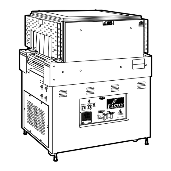
10 Introduction Introduction General System Description Model ET1608-30 Shrink Shrink Tunnel Tunnel Exit End Entrance Conveyor Conveyor Drive End Idler Vent Base / Slots Frame Model ET1610-36 & Model ET1610-48 Control Panel Control Panel Leveling AIRF LOW CONT ROL Casters... -
Page 11: Specifications
Designator Explanation of Model Numbers E = Manufactured by Eastey Enterprises Inc., in Engage Technologies Company. T = Tunnel. ET Series tunnel for shrink wrapping equipment. _ _ = 16 or 20 — First two digits indicate the nominal width of the chamber opening in inches: 16 or 20-inch chamber opening widths are available. - Page 12 12 Introduction Example: Model number ET1610-36V2-nnnn: ET indicates that it is an Eastey Shrink Tunnel. 1610 indicates the chamber width is 16 inches (chamber and conveyor width are the same) and chamber height is 10 inches. 36 indicates that the length of the chamber is 36 inches.
-
Page 13: Dimensions
Introduction 13 Dimensions Model ET1608-30 CAUTION Height PRECAUCION Conveyor Height 35.5 in. Approx. Width Length Front View Side View Model ET1610-36 & Model ET1610-48 AIRFLOW ADJUSTMEN T Height CAUTION PRECAUCION Conveyor Height 35.5 in. Approx. Length Width Side View Front View See A, B, and C dimensions in Specifications table for overall machine width, height, and length. - Page 14 14 Introduction Model ET2010-36 CAUTION Height PRECAUCION Conveyor Height 35.5 in. Approx. Width Length Front View Side View See A, B, and C dimensions in Specifications table for overall machine width, height, and length.
-
Page 15: Unpacking
We are willing to assist you in every reasonable manner to help you collect claims for loss or damage. However, this willingness on Eastey’s part does not make Eastey or its parent or related companies responsible for collections or claims or replacement of... -
Page 16: Installation
16 Installation Installation Carefully unpack the outer carton and shipping material. Although the exterior of the shrink tunnel is coated with a custom two part epoxy finish that resists scratching, avoid denting, scratching, or otherwise damaging the oven exterior. Lift the machine up and off of the shipping pallet. CAUTION! ET Performance Series Shrink Tunnels are heavy and may require a forklift, floor crane, or several people to move the... -
Page 17: Location Requirements
Installation 17 Location Requirements When installing the shrink tunnel please be aware of the following considerations: 1. The surface on which it is located is flat and level. 2. Conveyor or packing table height. 3. Alignment with packaging line. When the shrink tunnel is positioned in the operating location you will need access to the control panel. -
Page 18: Operation
18 Operation Operation Control Panel Control panel location may vary by model. Model 1608-30 and Model 2010-36, the control panel is located in the side of the base of the unit. Model 1610-36 and Model 1610-48, the control panel is located l above the tunnel entrance. -
Page 19: Controls
Operation 19 Controls Control Panels: Model 1608-30 and Model 2010-36; Model 1610-36 and Model 1610-48 POWER ON POWER ON ENCHUFE EN ENCHUFE EN APARADO APARADO HEATER BANK HEATER BANK BANCO de CALENTADORA BANCO de CALENTADORA BLOWER MOTOR SPEED CONVEYOR SPEED CONVEYOR SPEED VELOCIDAD de BLOWER VELOCIDAD de TRANSPORTADOR... -
Page 20: Sequence Of Operation
20 Operation Sequence of Operation 1. Turn on power to the shrink tunnel by toggling the Power switch near the upper left of the control panel to the On position. (The temperature in the tunnel will be displayed on the temperature control.) 2. -
Page 21: Adjustments
Adjustments 21 Adjustments Temperature Controller Settings (ETC00011) 1. PV = Processing value (red in color). 2. SV = Setting value (green in color). 3. Back ( ), forward ( ), down ( ), and up ( ) keys. 4. Programming key access door — Open to access programming keys. 5. -
Page 22: To Change The Set Value
22 Adjustments To Change the Set Value 1. Press the left-arrow ( ) button and a digit will begin to flash. The flashing digit indicates the digit whose value can be changed by pressing the down- ( ) or up- arrow ( ) buttons. - Page 23 Adjustments 23 To set AL-1 so the machine will shut down at 150°, press the left-arrow key and the right-most digit will flash. Use the up- or down-arrow key to select the digit, and then press the left-arrow key again. Use the up- or down-arrow key to set the digit and repeat until the correct value is displayed.
-
Page 24: Maintenance
24 Maintenance Maintenance To aid in the high reliability of the shrink tunnel, inspect the machine regularly and perform maintenance as required. Disconnect electrical power before making any repairs. Be very careful when servicing or adjusting this equipment. If in doubt, stop and obtain qualified help before proceeding. -
Page 25: Conveyor Belt Tension Adjustment
Maintenance 25 Check for loose fasteners. Tighten as necessary. Check the condition of the power cord for wear, especially if it is exposed to traffic. Check that the tunnel is able to maintain the set temperatures. If not, refer to the Adjustments Section of this User Guide for instruction. - Page 26 26 Maintenance NOTE: You must take the chain off the drive motor sprocket or the conveyor will not move freely. You must be able to move the conveyor to replace silicone covering on the rollers. 3. Remove old covering, by carefully slitting the covering and then pulling it off. 4.
-
Page 27: Replacing Tunnel Components
Maintenance 27 Replacing Tunnel Components Caution! Disconnect main power source before performing any procedure to replace any tunnel component(s). Fuse replacement or electrical component replacement Major electrical components, except the conveyor motor (whose replacement procedure is provided on the previous page) and the heater bank and blower motor (whose replacement procedures are provided separately below), are located behind the fold- down electrical control panel for easy maintenance. - Page 28 28 Maintenance For the second option (to replace entire controller and receptacle), first take note of wire locations (make a sketch and label the wires with tape, if necessary), and then disconnect wires from the temperature controller and thermocouple. Slide the controller and receptacle out of the front of the panel.
-
Page 29: Wire Belt Repair Splicing
Maintenance 29 Note: Do not rest blower housing on blower wheel! Blower wheel will not work if bent or out of balance. Blower wheel replacement Shut off power to the machine. Refer to Blower motor replacement instructions above. Placement of upper wear rails Shut off power to the machine, move the conveyor by hand if necessary to gain access. - Page 30 30 Maintenance Step 1 – Begin splicing in the center 1. Move the two ends of the belt to be spliced to the exit end of the conveyor. 2. Confirm that the edge loops curve back, away from the direction of belt travel as shown in the following illustration.
- Page 31 Maintenance 31 6. Pull the ends of the strand through until the center section “pops” or “locks” into place. (You should be pulling the strands toward you.) 7. Use pliers or the wire belt straightening tool to straighten the wire in the center space.
- Page 32 32 Maintenance 2. Bend the wire toward the center and insert it around the z-bend next to the center space. (Space D in the following illustration.) 3. Pull the strand wire through the mesh and straighten it with pliers. 4. Repeat the above three moves until you reach the side edge of the belt. 5.
- Page 33 Maintenance 33 2. If you are installing a new belt, you are finished splicing. Step 4 – Check Drive Shaft Sprocket Alignment Check to ensure 3/16-inch clearance between all sprockets (and/or blanks) and the Z-bends next to them. Check alignment of sprocket teeth with a straight-edge. (Only necessary if the sprockets are not keyed to the drive shaft.) Step 5 –...
-
Page 34: Troubleshooting
34 Troubleshooting Troubleshooting The following illustration shows the D.C. board used in the shrink tunnel. Some of the solutions to problems identified in the troubleshooting table that follows refer to adjustments made by tuning potentiometers on this board. Basic KBMM™ Controller Board Connection Diagram KBMM™... - Page 35 Troubleshooting 35 Problem Solution Conveyor not moving 1. The conveyor motor is controlled by a D.C. control board. Input is 220 VAC in and variable 0 to 90 VDC out. 2. Is a green light on? If not, check the input fuse. 3.
- Page 36 36 Troubleshooting Problem Solution No air flow 1. Check AC Inverter adjustable speed pot settings below. C.L.: Set at approximately 12 o’clock. Max.: All the way counter-clockwise. Min.: All the way clockwise. ACC.: All the way clockwise. ...
- Page 37 Troubleshooting 37 Color and Color and Flash Sequence After Drive Status Sequence Flash Rate Recovered Fault — Normal Operation (Run) Green 1 sec. On / Off Overload (120% – 160% Full On continuously Green Load — t (Drive Timed Out) 0.25 sec.
- Page 38 38 Troubleshooting Problem Solution No heat 1. Is the display on the temperature controller on? If not, check for 220 Volts on terminals 9 and 10. If there voltage, replace temperature controller. 2. If the display is on and SV is set higher than PV, is there a red light on? If not, replace the thermocouple.
- Page 39 Troubleshooting 39 Menu 2 Temperature Controller 1 Temperature Controller 2 Su-2 Su-2 (same as 1) AL-2 (same as 1) AHYS - AHYS - (same as 1) (same as 1) (same as 1) (same as 1) IN-B IN-B (same as 1) REST - REST - (same as 1)
-
Page 40: Parts List
40 Parts List Parts List This page is reserved for information that may be added later. - Page 41 Parts List 41 This page is reserved for information that may be added later.
-
Page 42: Appendix A: Electrical Schematic
42 Appendix A: Electrical Schematics Appendix A: Electrical Schematic Panel Layout Panel Layout for ET1608-30 & ET2010-36 POWER HEATER BANK DC CONTROL CONVEYOR BLOWER SPEED SPEED CONTROL CONTROL Panel Layout for ET1610-36 & ET1610-48 POWER HEATER BANK DC CONTROL CONVEYOR... -
Page 43: Electrical Schematic, Et1610-36/48 Variable Speed, 220V 40/50A / 480V 20/25A Single-Phase
Appendix A: Electrical Schematic 43 Electrical Schematic, ET1610-36/48 Variable Speed, 220V 40/50A / 480V 20/25A Single-Phase... - Page 44 44 Appendix A: Electrical Schematics This page is intentionally left blank.
-
Page 45: Electrical Schematic, Et1610-36/48, Variable Speed 220V, 25A, 3-Phase
Appendix A: Electrical Schematic 45 Electrical Schematic, ET1610-36/48, Variable Speed 220V, 25A, 3-Phase... - Page 46 46 Appendix A: Electrical Schematics This page is intentionally left blank.
-
Page 47: Electrical Schematic, Et2110, 220V, 40A, Single-Phase
Appendix A: Electrical Schematic 47 Electrical Schematic, ET2110, 220V, 40A, Single-Phase... - Page 48 48 Appendix A: Electrical Schematics This page is intentionally left blank.
-
Page 49: Electrical Schematic, Et2010, 220V, 25A, 3-Phase
Appendix A: Electrical Schematic 49 Electrical Schematic, ET2010, 220V, 25A, 3-Phase... - Page 50 50 Appendix A: Electrical Schematics This page is intentionally left blank.
-
Page 51: Warranty Statement
Eastey ET Shrink Tunnels Performance Series Warranty Statement Eastey Enterprises warrants that all of the products it ships will be in good working order and free from defects in material and workmanship for a period of two (2) years from the date of shipment by Eastey and will conform to the published specifications for that product. - Page 52 LIABLE FOR ANY SPECIAL, CONSEQUENTIAL, INDIRECT OR SIMILAR DAMAGES, INCLUDING LOST PROFIT OR LOST OPPORTUNITIES OF ANY TYPE ARISING OUT OF THE USE OR INABILITY TO USE THESE PRODUCTS EVEN IF EASTEY ENTERPRISES, INC. HAS BEEN ADVISED OF THE POSSIBILITY OF SUCH...
-
Page 53: Customer Support
Eastey Technical Service at one of the numbers listed below. Toll-Free Phone 800-835-9344 Phone 763-428-4846 763-795-8867 E-mail info@eastey.com www.eastey.com Thank you again for your purchase of Eastey products. We are pleased to be a part of your packaging needs.
Need help?
Do you have a question about the ET1608-30 and is the answer not in the manual?
Questions and answers