Table of Contents
Advertisement
Quick Links
Advertisement
Table of Contents

Subscribe to Our Youtube Channel
Related Manuals for Eastey BB-2T


Summary of Contents for Eastey BB-2T
- Page 1 BB-2/3T Bottom Belt Case Taping System User Guide...
- Page 3 Copyright and Trademarks Copyright ©2015-2019 Engage Technologies Corporation All rights reserved. All trademarks and brand names are the property of their respective owners. Eastey 7041 Boone Ave. N. Brooklyn Park, MN 55428 Phone: (763) 428-4846; Fax (763) 795-8867; 1-800-835-9344 www.eastey.com...
-
Page 5: Table Of Contents
Contents: Safety ..........................7 Introduction ........................8 BB-2/3T Case Taper Overview ..................8 Specifications ........................ 9 Dimensions ......................... 10 Installation ........................11 Install Casters ......................11 Set Machine Height ..................... 11 Location Requirements ....................12 Install Front and Rear Tables ..................13 Next Steps ........................ -
Page 7: Safety
Safety 7 Safety Safety Precautions Before installing, operating or servicing this equipment, please read the following precautions carefully: • This machine is equipped with moving belts. Do not place hands near the belts when they are moving, as fingers may be pinched where belts descend under the exit table or into the frame. -
Page 8: Introduction
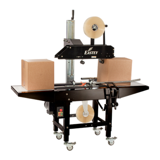
8 Introduction Introduction BB-2/3T Case Taper Overview Height Adjustment Crank Tape Sealer Heads (Top and Mast Bottom) Machine Body Adjustable Side Guide Rails (Left and Right) Control Panel Pack Table (Standard Front and Rear) Adjustable Locking Casters (Standard) -
Page 9: Specifications
Introduction 9 Specifications Model BB-2T Tape 2 inches (50 mm) tape width, up to 15 inches (36 cm) diameter rolls Belt Speed 60 feet/min (19 m/min) (L) 6 inches (15 cm) to unlimited Capacity (W) 6 to 21 inches (15 to 53.3 cm) (H) 4 to 20.5 inches (10 to 52 cm) -
Page 10: Dimensions
10 Introduction Dimensions Dimensions shown are in inches. -
Page 11: Installation
Installation 11 Installation The BB-2/3T Case Taper is shipped boxed and mounted on a shipping pallet. The case taper is mostly assembled with the exception that the front and rear tables and casters and any optional components such as top squeezers are not attached. Remove the cardboard packaging from the machine and lift the machine up and off of the shipping pallet. -
Page 12: Location Requirements
12 Installation Move Taper To Required Location CAUTION! If the case taper must be lifted for moving, use proper equipment when lifting and moving the case taper to ensure the case taper is secure and will not shift. Set up the case taper and move it to its location. The casters allow easy movement over smooth flat surfaces. -
Page 13: Install Front And Rear Tables
Installation 13 Install Front and Rear Tables Front and rear tables are identical and therefore interchangeable. Temporarily loosen socket head cap screws at the locations shown in the following illustration. Align the keyhole slots in the table flanges with the loosened cap screw heads and position table with conveyor belts, then re-tighten cap screws to secure table. -
Page 14: Next Steps
14 Installation Next Steps Follow instructions in the Operation section for instructions to load the tape cartridges in the upper and lower tape heads. Refer to the Adjustments section for instructions to make necessary height and width adjustments that must be made for operation of the box taper. Refer to instructions in the Operation section for instructions to power or shut down the machine. -
Page 15: Operation
Operation 15 Operation Load Tape Press the Stop switch and disconnect the power. CAUTION! To avoid personal injury, remove the tape cartridge before loading tape. When handling the tape cartridge be careful to avoid contact with the tape cutting blade. The taping cartridge in the upper head assembly is secured in place by a single wing bolt (winged-head cap screw). -
Page 16: Check Tension
Tape Head User Guide provided with the tape head. For convenience, diagrams for threading tape in the Eastey-EX Tape Head and EZ-EX Tape Head are provided on the following page. Follow the diagram that applies for your... - Page 17 Operation 17 Eastey-EX Tape Head Adhesive Side Adhesive Side Upper Cartridge Bottom Cartridge EZ-EX Tape Head Adhesive Side Adhesive Side Upper Cartridge Bottom Cartridge...
-
Page 18: Main Spring
18 Operation Center Tape — Eastey-EX Tape Head only Make sure the tape is centered on all the rollers. There are several rollers in the tape cartridge where the tape alignment should be checked to verify the tape stays on center as it is being dispensed. -
Page 19: Control Panel
Operation 19 Control Panel Emergency Stop Stop Start Emergency Stop Button Press the button for emergency stop. Stop Press to stop motors and belts but keep power to the system on. (Non-emergency stop.) Start Press to start motors and belts. Start and stop buttons are covered by a clear plastic to protect them from dust, dirt, etc. -
Page 20: Adjustments
20 Adjustments Adjustments Box Width and Height Adjustment Place a box filled with product on the in-feed table. Position the box centered with the conveyor drive belt and tape heads. Use the filled box to adjust the width of guide rails and top tape head height to accommodate the box width and height as explained in the instructions that follow. -
Page 21: Guide Rail Adjustment
Adjustments 21 Guide Rail Adjustment The purpose of the guide rails is to guide the box into the center of the machine as it is fed into the conveyor from the in-feed table. Keeping the box centered on the conveyor keeps the tape heads centered with the box, which keeps the tape seal on-center as it is applied to the box on the top or bottom seams. -
Page 22: Top Tape Head Height Adjustment
22 Adjustments Top Tape Head Height Adjustment Use the hand crank at the top of the mast to adjust the top tape head height to accommodate box height, as shown in the following illustration. Turn the crank counter- clockwise to raise the tape head. Turn the crank clockwise to lower the tape head. Rotate top crank handle to raise or lower top tape... -
Page 23: Belt Adjustment
Adjustments 23 Belt Adjustment To adjust the belt tension, loosen the hex socket cap screws (A) in the slotted holes in the belt housing below the idler, then adjust the hex socket tensioning screws (B) in the end. When belt is set to the required tension, re-tighten the hex socket cap screws (A). Tensioning Screws (B) Hex Socket Cap... -
Page 24: Maintenance
24 Maintenance Maintenance The BB-2/3T Case Taping System will provide many hours of maintenance free operation. There are a few items that may require attention from time to time. Rollers Make sure rollers stay clean and grease free. If you should have to clean the rollers simply wipe them down with a clean lint-free cloth. -
Page 25: Changing Drive Belts
Maintenance 25 Changing Drive Belts Turn off and unplug the taper. Loosen the tension on the belt completely. Drive Idler Loosen Drive Pulley Pulley Belt Loosen Tension With the belt loose, remove the connecting pin that holds the belt together. Connecting Pin Drive Belt... - Page 26 26 Maintenance Take the belt off the machine. Install the new belt around the drive and idler pulleys. While the belt is still loose, connect the ends by lining up the loops and replacing the connecting pin. Connecting Pin Drive Belt...
- Page 27 Maintenance 27 Using the tensioning bolts, restore tension on the idler pulley. Idler Pulley Restore Tension Drive Pulley Idler Pulley Re-tighten Retighten the socket head cap screws in the bottom of the conveyor to secure the idler pulley brackets in place. Plug in and turn on the BB-2/3T Case Taper to resume taping.
-
Page 28: Troubleshooting
28 Troubleshooting Troubleshooting Problem Solution Machine is not operating • Machine has inadequate electrical power or power is not connected. Verify system power meets specification requirements. • An Emergency Stop condition exists. Clear the machine and reset the Emergency Stop. Machine cannot tape cartons •... - Page 29 • Check to be sure tape is threaded properly on front roller (page 17). • Check wipe down brush. Tape Curling and Bunching Up Eastey-EX Tape Head Only — Eastey-EX Tape Head Only • Adjust tape cartridge height (approximately .06 inches from box) •...
-
Page 30: Parts List
30 Illustrated Parts List Parts List Electrical... - Page 31 Illustrated Parts List 31 Electrical Layout Motor Detail ITEM DESIGNATOR PART NUMBER DESCRIPTION OLD PART NO. Q’TY. 5001264-BBT-V1 ELECTRICAL BOX, 230 V P0323-0000600 5001264-BBT-V0 ELECTRICAL BOX 110 V P0323-0000700 5005197 FUSE P0305-030002600 5001714-TB MOTOR 110V/60Hz T18:1 745111M1 MOTOR 110V/50Hz T15:1 745111M2 MOTOR 210V/60Hz T18:1 745122M1...
-
Page 32: Machine Body And Tables
32 Illustrated Parts List Machine Body and Tables... - Page 33 Illustrated Parts List 33 ITEM PART NO. DESCRIPTION OLD PART NO. Q’TY 5004137 MACHINE FRAME KA11106710 5004132 PLATE A CA33060A 5004138 CONNECTING BASE KA11108000 5004139 SAFETY COVER DA11107400 5002147 GUIDE RAIL (SQUEEZER) BAR (R) KA030520R0 5002116 GUIDE RAIL (SQUEEZER) BAR (L) KA030520L0 5004140 CAP PLUG...
- Page 34 34 Illustrated Parts List ITEM PART NO. DESCRIPTION OLD PART NO. Q’TY 5004151 ROLLER KA30016700 5004152 BELT ROLLER SUPPORT KA11108400 5004153 CASTER FIXER P01-022400A 5004154 FIXED PLATE KA11107800 5004155 P01-020000C 5004156 FIXED PLATE KA11107900 5002107 ADJUSTABLE LEG KA11107700 5001902 CASTER, SWIVEL, LOCKING KA04010800 5004157 CONTROL BOX FIX PLATE...
-
Page 35: Mast And Upper Tape Head Seat
Illustrated Parts List 35 Mast and Upper Tape Head Seat... - Page 36 36 Illustrated Parts List ITEM PART NO. DESCRIPTION OLD PART NO. Q’TY 5004162 UPPER TAPER SEAT KA11106910 5004163 UPPER TAPER FRONT PLATE KA11107010 5004164 PLATE HOLDING SHAFT KA03051210 5001696B UPPER BLOCK B CA100300 5004165 UPPER TAPER SHIELD KA11108110 5004166 PLATE HOLDING SHAFT KA03051100 5004167 COLUMN...
-
Page 37: Appendix A: Electrical Schematic
Appendix A: Electrical Schematic 37 Appendix A: Electrical Schematic... -
Page 38: Warranty Statement
Warranty Statement BB-2/3T Case Taping System Warranty Statement Eastey warrants that all of the products it ships will be in good working order and free from defects in material and workmanship and will conform to the published specifications for that product. - Page 39 ESSENTIAL PURPOSE, IN NO EVENT WILL EASTEY BE LIABLE FOR ANY SPECIAL, CONSEQUENTIAL, INDIRECT OR SIMILAR DAMAGES, INCLUDING LOST PROFIT OR LOST OPPORTUNITIES OF ANY TYPE ARISING OUT OF THE USE OR INABILITY TO USE THESE PRODUCTS EVEN IF EASTEY HAS BEEN ADVISED OF THE POSSIBILITY OF SUCH DAMAGES.
-
Page 40: Customer Support
For help setting up or operating the BB-2/3T Case Taper, please contact Eastey Technical Service at one of the numbers listed below. Toll-Free Phone 800-835-9344 Phone 763-428-4846 763-795-8867 E-mail info@eastey.com www.eastey.com Thanks again for your purchase of Eastey products. We are pleased to be a part of your packaging needs.
Need help?
Do you have a question about the BB-2T and is the answer not in the manual?
Questions and answers