Table of Contents
Advertisement
Advertisement
Chapters
Table of Contents

Related Manuals for Kaisai KMK-60RY1


Summary of Contents for Kaisai KMK-60RY1
- Page 1 SERVICE MANUAL SPLIT TYPE HEAT PUMP...
- Page 2 Split...
- Page 3 Split M thermal Split CONTENTS Part 1 General Information ................3 Part 2 Component Layout and Refrigerant Circuits ........7 Part 3 Control ....................17 Part 4 Diagnosis and Troubleshooting ............31 202004 Midea CAC Confidential...
- Page 4 Split M thermal Split 202004 Midea CAC Confidential...
- Page 5 Split M thermal Split Part 1 General Information 1 Unit Capacities ................... 4 2 External Appearance .................. 5 202004 Midea CAC Confidential...
- Page 6 The full model names can be obtained by substituting the asterisk in the model name format given in the left-hand column of the table above with the KHA-10RY1 shortened model names given in the table. For example, the model name for the 10kW model is 1.2 Hydronic Box Model Table 1-1.2: Model Model KMK-60RY1 KMK-100RY1 KMK-160RY3 KHA-06RY1 KHA-08(10)RY1 KHA-12(14, 16)RY3...
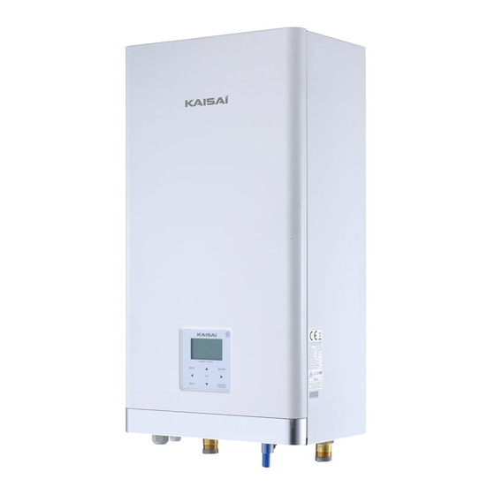
- Page 7 Split M thermal Split 2 External Appearance 2.1 Outdoor Unit Appearance Table 1-2.1: Outdoor unit appearance KHA-08(10)RY1 KHA-06RY1 KHA-12(14,16)RY3 2.2 Hydronic Box Appearance Table 1-2.2: Hydronic box appearance KMK-60RY1 KMK-100RY1 KMK-160RY1 202004 Midea CAC Confidential...
- Page 8 Split M thermal Split 202004 Midea CAC Confidential...
- Page 9 Split M thermal Split Part 2 Component Layout and Refrigerant Circuits Layout of Functional Components ............8 Piping Diagrams .................. 13 Refrigerant Flow Diagrams ..............15 202004 Midea CAC Confidential...
- Page 10 Split M thermal Split 1 Layout of Functional Components 1.1 Outdoor Unit Layout KHA-06RY1 Figure 2-1.1: KHA-06RY1 top view Figure 2-1.2: KHA-06RY1 front view 202004 Midea CAC Confidential...
- Page 11 Split M thermal Split KHA-08(10)RY1 Figure 2-1.3: KHA-08(10)RY1 top view Figure 2-1.4: KHA-08(10)RY1 front view 202004 Midea CAC Confidential...
- Page 12 Split M thermal Split KHA-12(14,16)RY3 Figure 2-1.7: KHA-12(14,16)RY3 top view 202004 Midea CAC Confidential...
- Page 13 Split M thermal Split Figure 2-1.8: KHA-12(14,16)RY3 front view 202004 Midea CAC Confidential...
- Page 14 Split M thermal Split 1.2 Hydronic Box Layout Figure 2-1.9: KMK-60(100, 160)RY1(3) oblique view Air purge valve Water flow switch Water side heat exchanger Electric control box Expansion vessel Water pump Manometer Safety valve 202004 Midea CAC Confidential...
- Page 15 Split M thermal Split 2 Piping Diagrams 2.1 Outdoor Unit Piping Figure 2-2.1: Outdoor unit piping diagram Air side heat exchanger 12.1 12.2 Legend Compressor Electronic expansion valve Discharge pipe temperature sensor Stop valve (liquid side) Outdoor ambient temperature sensor Stop valve (gas side) Air side heat exchanger refrigerant outlet temperature sensor Pressure sensor...
- Page 16 Split M thermal Split 2.2 Hydronic box Piping Figure 2-2.2: Hydronic box piping diagram Legend Water side heat exchanger Water pump Water flow switch Manometer Refrigerant liquid line temperature sensor Safety valve Refrigerant gas line temperature sensor Refrigerant gas side Water outlet temperature sensor Refrigerant liquid side Water inlet temperature sensor...
- Page 17 Split M thermal Split 3 Refrigerant Flow Diagrams Heating and domestic hot water operation Figure 2-3.1: Refrigerant flow during heating or domestic hot water operation High temperature, high pressure gas High temperature, high pressure liquid Low temperature, low pressure Hydronic box Pressure sensor Stop valve 4-way...
- Page 18 Split M thermal Split 202004 Midea CAC Confidential...
-
Page 19: Table Of Contents
Split M thermal Split Part 3 Control 1 Stop Operation ..................18 2 Standby Control ..................18 3 Startup Control ..................19 4 Normal Operation Control ............... 22 5 Protection Control ................... 23 6 Special Control ..................26 7 Role of Temperature Sensors in Control Functions ........29 202004 Midea CAC Confidential... -
Page 20: Stop Operation
Split M thermal Split 1 Stop Operation The stop operation occurs for one of the following reasons: 1. Abnormal shutdown: in order to protect the compressors, if an abnormal state occurs the system makes a stop with thermo off operation and an error code is displayed on the outdoor unit PCB digital displays and on the user interface. 2. -
Page 21: Startup Control
Split M thermal Split 3 Startup Control 3.1 Compressor Startup Delay Control In initial startup control and in restart control (except in oil return operation and defrosting operation), compressor startup is delayed such that a minimum of the set re-start delay time has elapsed since the compressor stopped, in order to prevent frequent compressor on/off and to equalize the pressure within the refrigerant system. - Page 22 Split M thermal Split Figure 3-3.3: KHA-08(10)RY1 compressor startup program when ambient temperature is above 11°C Compressor rotation speed (rps) Target rotation speed 82rps 70rps 66rps 120s 56rps 42rps 42rps 36rps Time (s) Notes: 1. Once the first, 90-second stage of the program is complete, the program proceeds to the subsequent stages in a step-by-step fashion and exits when the target rotation speed has been reached.
- Page 23 Split M thermal Split Figure 3-3.6: KHA-12(14, 16)RY3 compressor startup program when ambient temperature is at or below 3°C Compressor rotation speed (rps) Target rotation speed 82rps 70rps 66rps 240s 56rps 240s 42rps 38rps 34rps 24rps Time (s) Notes: Once the first, 40-second stage of the program is complete, the program proceeds to the subsequent stages in a step-by-step fashion and exits when the target rotation speed has been reached.
-
Page 24: Normal Operation Control
Split M thermal Split 4 Normal Operation Control 4.1 Component Control during Normal Operation Table 3-4.1: Component control during heating and domestic hot water operations Component Wiring diagram label Control functions and states 6-16kW Inverter compressor Controlled according to load requirement from hydronic system COMP ●... -
Page 25: Protection Control
Split M thermal Split 4.6 Outdoor Fan Control The speed of the outdoor unit fan is adjusted in steps, as shown in Table 3-4.1. Table 3-4.3: Component control during cooling operation Fan speed (rpm) Fan speed index 16kW 6/8/10kW 12/14kW 5 Protection Control 5.1 High Pressure Protection Control This control protects the refrigerant system from abnormally high pressure and protects the compressor from transient... - Page 26 Split M thermal Split When the suction pressure drops below 0.14MPa the system displays P0 protection and the unit stops running. When the suction pressure rises above 0.3MPa, the compressor enters re-start control. 5.3 Discharge Temperature Protection Control This control protects the compressor from abnormally high temperatures and transient spikes in temperature. Figure 3-5.3: High discharge temperature protection control Normal operation Discharge temperature >...
- Page 27 Split M thermal Split 5.5 Voltage Protection Control This control protects the Split from abnormally high or abnormally low voltages. Figure 3-5.6: Compressor voltage protection control Normal operation Single phase model: Voltage ≥ Single phase model: Voltage < 265V for 30s or Voltage ≤ 172V 256V for 30s or Voltage ≥...
-
Page 28: Special Control
Split M thermal Split 6 Special Control 6.1 Oil Return Operation In order to prevent the compressor from running out of oil, the oil return operation is conducted to recover oil that has flowed out of the compressor and into the refrigerant piping. The oil return operation starts when the following condition occurs: ... - Page 29 Split M thermal Split Table 3-6.4: Component control during force cool operation Wiring diagram Component Control functions and states 6-16kW label Inverter compressor Runs at force cooling operation rotation speed COMP ● Runs at force cooling operation speed DC fan motor ●...
- Page 30 Split M thermal Split 6.6 Smart grid control Unit adjusts the operation according to different electrical signals to realize energy saving. Free electric energy signal: DHW mode turn on, the setting temperature will be changed to 70℃ automatically, and the TBH operate as below:T5<69.
-
Page 31: Role Of Temperature Sensors In Control Functions
Split M thermal Split 7 Role of Temperature Sensors in Control Functions Figure 3-7.1: Location of the temperature sensors on Split systems Figure 3 -7.1: Locati o n of the t emperature s Mn o Thermal Spli t s y st ems Notes: Notes: The names and functions of the temperature sensors labelled 1 to 11 in this figure are detailed in Table 3-7.1. - Page 32 Split M thermal Split Table 3-7.1: Names of the temperature sensors Number Sensor name Sensor code Suction pipe temperature sensor Discharge pipe temperature sensor Outdoor ambient temperature sensor Air side heat exchanger refrigerant outlet temperature sensor Water side heat exchanger refrigerant outlet (gas pipe) temperature sensor Water side heat exchanger...
- Page 33 Split M thermal Split Part 4 Diagnosis and Troubleshooting 1 Electric Control Box Layout ............... 32 2 PCBs ......................35 3 Error Code Table ..................49 4 Troubleshooting ..................51 5 Appendix to Part 4 ................. 107 202004 Midea CAC Confidential...
-
Page 34: Electric Control Box Layout
Split M thermal Split 1 Electric Control Box Layout 1.1 Outdoor Unit Electric Control Box Layout Figure 4-1.1: KHA-06RY1 electric control box Main PCB Inverter module Figure 4-1.2: KHA-08(10)RY1 electric control box Main PCB Inverter module 202004 Midea CAC Confidential... - Page 35 Split M thermal Split Figure 4-1.4: KHA-12(14,16)RY3 electric control box Main PCB Inverter module Main Power Electric Reactor Filter board DCFAN Electric Reactor 202004 Midea CAC Confidential...
- Page 36 Split M thermal Split 1.2 Hydronic Box Electric Control Box Layout Figure 4-1.5: KMK-60(100, 160)RY1(3) Main control board 202004 Midea CAC Confidential...
-
Page 37: Pcbs
Split M thermal Split 2 PCBs 2.1 Outdoor Unit PCBqsss There are one type of main PCB for the 4kW to 16kW models. In addition to the main PCB, all models have an inverter module. The locations of each PCB in the outdoor unit electric control box are shown in Figures 4-1.1 to Figure 4-1.4 in Part 4, 1.1 “Outdoor Unit Electric Control Box Layout”. - Page 38 Split M thermal Split Table 4-2.1: KMK-60(100, 160)RY1(3) hydronic box main PCB Label in Figure Code Content 4-2.1 CN21 Port for power supply Rotary dip switch DIS1 Digital display Port for ground CN28 Port for variable speed pump power input CN25 Port for IC programming S1,S2,S4...
- Page 39 Split M thermal Split 2.3 Main PCBs for Refrigerant System, Inverter Module Figure 4-2.2: KHA-06(08,10)RY1 outdoor unit main PCB for refrigerant system 27 26 25 24 22 21 20 202004 Midea CAC Confidential...
- Page 40 Split M thermal Split Table 4-2.2: KHA-06(08,10)RY1 outdoor unit main PCB for refrigerant system Label in Figure Code Content 4-2.2 Ourput port L to main PCB for refrigerant system CN28 Reserved CN22 Output port N to main PCB for refrigerant system CN27 Reserved Port for ground wire...
- Page 41 Split M thermal Split 202004 Midea CAC Confidential...
- Page 42 Split M thermal Split 202004 Midea CAC Confidential...
- Page 43 Split M thermal Split Figure 4-2.4 KHA-12(14,16)RY3 outdoor unit main PCB for refrigerant system 26 25 24 23 22 21 20 19 18 17 16 15 14 202004 Midea CAC Confidential...
- Page 44 Split M thermal Split Table 4-2.4: KHA-12(14,16)RY3 outdoor unit main PCB for refrigerant system Label in Figure Code Content 4-2.4 Port for GND CN38 Port for 2-way valve 6 CN27 Port for 2-way valve 5 CN20 Port for eletric heating tape2 Port for eletric heating tape1 CN10 Reserved...
- Page 45 Split M thermal Split Figure 4-2.5 KHA-06(08,10)RY1 outdoor unit inverter module For 4/6kW model For 8/10kW model 202004 Midea CAC Confidential...
- Page 46 Split M thermal Split Table 4-2.5: KHA-06(08,10)RY1 outdoor unit inverter module Label in Code Content Figure 4-2.5 Compressor connection port U Compressor connection port V Compressor connection port W Output port for +12V/9V CN20 Port for fan CN19 Port for communication with main PCB for filter board CN32 Input port N for rectifier bridge CN502...
- Page 47 Split M thermal Split Figure 4-2.7: KHA-12(14,16)RY3 outdoor unit inverter module 202004 Midea CAC Confidential...
- Page 48 Split M thermal Split Table 4-2.7: KHA-12(14,16)RY3 outdoor unit inverter module Label in Code Content Figure 4-2.7 Output port for +15V CN20 Compressor connection port W CN19 Compressor connection port V CN18 Compressor connection port U CN17 Power Input port L3 CN15 Power Input port L2 Input port P_out for IPM module...
- Page 49 Split M thermal Split Figure 4-2.8: KHA-12(14,16)RY3 outdoor unit filter board Table 4-2.8: KHA-12(14,16)RY3 outdoor unit filter board Label in Code Content Figure 4-2.8 Power supply L2 CN201 Power supply L3 CN200 Power supply N CN203 Power supply port of 310VDC CN212 Reserved CN211...
- Page 50 Split M thermal Split 2.4 Digital Display Output Table 4-2.9: Digital display output in different operating states Parameters displayed on outdoor Parameters displayed on hydronic Split system state unit main PCB DSP1 box main PCB DSP1 On standby Running speed of the compressor in Leaving water temperature (°C) Normal operation rotations per second...
-
Page 51: Error Code Table
Split M thermal Split 3 Error Code Table Table 4-3.1: Error code table Error Serial Content Remarks code Number High temperature protection of transducer module Water flow failure(E8 appears for 3 times) Phase sequence error Only applies to 3-phase models Communication error between the main control board of hydraulic module and user interface Final outlet water temperature sensor error... - Page 52 Split M thermal Split Table 4-3.1: Error code table (continued) High temperature difference between water side heat exchanger water inlet and water outlet temperatures protection Inverter module protection Inverter module protection DC bus low voltage protection DC bus high voltage protection MCE error Zero speed protection Phase sequence error...
-
Page 53: Troubleshooting
Split M thermal Split 4 Troubleshooting 4.1 Warning Warning All electrical work must carried by competent and suitably qualified, certified accredited professionals and in accordance with all applicable legislation (all national, local and other laws, standards, codes, rules, regulations and other legislation that apply in a given situation). ... - Page 54 Split M thermal Split 4.2 E0, E8 Troubleshooting 4.2.1 Digital display output 4.2.2 Description Water flow failure. E0 indicates E8 has displayed 3 times. When an E0 error occurs, a manual system restart is required before the system can resume operation. ...
- Page 55 Split M thermal Split 4.2.4 Procedure E0 / E8 Water flow switch connection on Ensure the switch is connected properly hydronic box main PCB is loose Check the water piping and valves. Make sure the water piping is clean, there is no air in the water piping and all valves are Water flow is insufficient open.
- Page 56 Split M thermal Split 4.3 E1 Troubleshooting 4.3.1 Digital display output 4.3.2 Description Phase sequence error. Only applies to 3-phase models. Split stops running. Error code is displayed on outdoor unit main PCB and user interface. 4.3.3 Possible causes ...
- Page 57 Split M thermal Split 4.3.4 Procedure The phase sequence of the 3-phase Exchange any two of the 3 phase wires power supply is incrorrect Ensure all supply terminals are securely Some power supply terminals are loose fastened The power supply is abnormal Check the power supply equipment Replace outdoor unit main PCB Notes:...
- Page 58 Split M thermal Split 4.4 E2 Troubleshooting 4.4.1 Digital display output 4.4.2 Description Communication error between hydronic box and user interface. Split stops running. Error code is displayed on hydronic box main PCB and user interface. 4.4.3 Possible causes ...
- Page 59 Split M thermal Split 4.4.4 Procedure Communication wires X Y E have short circuited, disconnected or are Reconnect the communication wires misconnected Communication wires X Y E are not Connect the communication wires in a connected in a daisy chain daisy chain Wires between hydronic box main PCB and electric control box communication...
- Page 60 Split M thermal Split 4.5 E3, E4, H2, H3, Ed, HA, H5, H9, Eb, E7,Ec Troubleshooting 4.5.1 Digital display output 4.5.2 Description E3 indicates final outlet water temperature sensor error E4 indicates a domestic hot water tank temperature sensor error. ...
- Page 61 Split M thermal Split 4.5.4 Procedure E3 / E4 / H2 / H3 / Ed / HA / H5 / H9/ Eb / E7 / Ec Temperature sensor connection on Ensure the sensor is connected properly hydronic box main PCB is loose Temperature sensor has short-circuited Replace the sensor or failed...
- Page 62 Split M thermal Split 4.6 E5, E6, E9, EA Troubleshooting 4.6.1 Digital display output 4.6.2 Description E5 indicates an air side heat exchanger refrigerant outlet temperature sensor error. E6 indicates an outdoor ambient temperature sensor error. E9 indicates a suction pipe temperature sensor error. ...
- Page 63 Split M thermal Split 4.6.4 Procedure E5 / E6 / E9 / EA Temperature sensor connection on Ensure the sensor is connected properly outdoor unit main PCB is loose Temperature sensor has short-circuited Replace the sensor or failed Replace outdoor unit main PCB Notes: Air side heat exchanger refrigerant outlet temperature sensor and outdoor ambient temperature sensor connections are port CN9 on the KHA-06(08,10)RY1 outdoor unit refrigerant system main PCB (labeled 12 in Figure 4-2.2 in Part 4, 2.1 “Main PCBs for Refrigerant System, Inverter...
- Page 64 Split M thermal Split 4.7 EE Troubleshooting 4.7.1 Digital display output 4.7.2 Description Hydronic box main PCB EEPROM error. Split stops running. Error code is displayed on hydronic box main PCB and user interface. 4.7.3 Possible causes ...
- Page 65 Split M thermal Split 4.8 F1 Troubleshooting 4.8.1 Digital display output 4.8.2 Description Low DC generatrix voltage. Split stops running. Error code is displayed on hydronic system main PCB and user interface. 4.8.3 Possible causes The DC generatrix voltage is too low. 4.8.4 Procedure Power supply is abnormal.
- Page 66 Split M thermal Split 4.9 HF Troubleshooting 4.9.1 Digital display output 4.9.2 Description Outdoor unit inverter module EEPROM error. Split stops running. Error code is displayed on outdoor unit main PCB and user interface. 4.9.3 Possible causes ...
- Page 67 Split M thermal Split 4.10 H0 Troubleshooting 4.10.1 Digital display output 4.10.2 Description Communication error between outdoor unit and hydronic box. Split stops running. Error code is displayed on hydronic box main PCB, outdoor unit main PCB and user interface.
- Page 68 Split M thermal Split 4.10.4 Procedure Power supply for the main control board Provide normal power supply and transformer is abnormal The transformer of hydronic unit is Replace the transformer malfunctioned There is a source of electromagnetic radiation near the unit, such as Remove the source of interference high-frequency transmitter or other high strength radiation device...
- Page 69 Split M thermal Split 4.11 H1 Troubleshooting 4.11.1 Digital display output 4.11.2 Description Communication error between outdoor unit main control board and inverter module. Split stops running. Error code is displayed on outdoor unit main PCB and user interface. 4.11.3 Possible causes ...
- Page 70 Split M thermal Split 4.12 H6, HH Troubleshooting 4.12.1 Digital display output 4.12.2 Description H6 indicates a DC fan error. HH indicates that H6 protection has occurred 10 times in 2 hours. When HH error occurs, a manual system restart is required before the system can resume operation.
- Page 71 Split M thermal Split 4.12.4 Procedure H6 / HH is blowing towards the fan, making Change the outdoor unit’s installation direction or the fan running in the wrong direction build a shelter to protect the fan from strong wind DC fan wire is loosed Reconnect DC fan wire The fan motor is blocked or has failed Remove obstruction or replace the fan motor...
- Page 72 Split M thermal Split 4.13 H7 Troubleshooting 4.13.1 Digital display output 4.13.2 Description Abnormal main circuit voltage. Split stops running. Error code is displayed on outdoor unit main PCB and user interface. 4.13.3 Possible causes Power supply voltage not within 90%~110% of rated voltage. ...
- Page 73 Split M thermal Split 4.14 H8 Troubleshooting 4.14.1 Digital display output 4.14.2 Description Pressure sensor error. Split stops running. Error code is displayed on outdoor unit main PCB and user interface. 4.14.3 Possible causes Pressure sensor not connected properly or has malfunctioned. ...
- Page 74 Split M thermal Split 4.15 P0, HP Troubleshooting 4.15.1 Digital display output 4.15.2 Description P0 indicates suction pipe low pressure protection. When the suction pressure falls below 0.14MPa, the system displays P0 protection and Split stops running. When the pressure rises above 0.3MPa, P0 is removed and normal operation resumes.
- Page 75 Split M thermal Split 4.15.4 Procedure P0 / HP Insufficient refrigerant caused by Add refrigerant or inspect the system for refrigerant leakage leaks The low pressure side is blocked, caused Inspect the system and fix the error. If the by crushed or bent pipe, blocked EXV, or filter is blocked by ice, the piping should dirty filter be cleaned...
- Page 76 Split M thermal Split 4.16 P1 Troubleshooting 4.16.1 Digital display output 4.16.2 Description Discharge pipe high pressure protection. When the discharge pressure rises above 4.3MPa, the system displays P1 protection and Split stops running. When the discharge pressure falls below 3.6MPa, P1 is removed and normal operation resumes.
- Page 77 Split M thermal Split 4.16.4 Procedure High pressure switch connection or Ensure the pressure switch is connected pressure sensor connection on outdoor properly unit main PCB is loose Pressure sensor has short-circuited or Replace the pressure sensor failed The high pressure side is blocked, caused Inspect the system and fix the error by crushed or bent pipe or blocked EXV The heat exchange is poor...
- Page 78 Split M thermal Split 4.17 P3 Troubleshooting 4.17.1 Digital display output 4.17.2 Description Compressor current protection. When the compressor current rises above the protection value (6kW models 18A, 8/10kW model 19A, 12/14/16kW single phase model 30A, 12/14/16kW three phase model 14A,), the system displays P3 protection and Split stops running.
- Page 79 Split M thermal Split 4.17.4 Procedure The condenser heat exchange is poor Inspect the system and fix the error The high pressure side is blocked, caused Inspect the system and fix the error by crushed or bent pipe or blocked EXV Inverter module has short-circuited Replace the inverter module Compressor has malfunctioned...
- Page 80 Split M thermal Split 4.18 P4 Troubleshooting 4.18.1 Digital display output 4.18.2 Description Discharge temperature protection. When the compressor the discharge temperature rises above 115°C, the system displays P4 protection and Split stops running. When the discharge temperature falls below 95°C , P4 is removed and normal operation resumes. ...
- Page 81 Split M thermal Split 4.18.4 Procedure Discharge pipe temperature sensor Ensure the temperature sensor is connection on outdoor unit main PCB is connected properly loose Final outlet water temperature sensor connection, domestic hot water tank temperature sensor connection or water Ensure the temperature sensor is side heat exchanger water outlet connected properly...
- Page 82 Split M thermal Split port CN4 on the KHA-12(14,16)RY3 outdoor unit refrigerant system main PCB (labeled 15 in Figure 4-2.4 in Part 4, 2. 3 "Main PCB for Refrigerant System, Inverter Module"). Final outlet water temperature sensor and water side heat exchanger water outlet temperature sensor connections are port CN6 on the hydronic box main PCB (labeled 10 in Figure 4-2.1 in Part4, 2.2 "Main PCB for Hydronic System").
- Page 83 Split M thermal Split 4.19 P5 Troubleshooting 4.19.1 Digital display output 4.19.2 Description High temperature difference between water side heat exchanger water inlet and water outlet temperatures protection. Split stops running. Error code is displayed on hydronic box main PCB and user interface. 4.19.3 Possible causes ...
- Page 84 Split M thermal Split 4.19.4 Procedure Water side heat exchanger water inlet / Ensure the temperature sensor is outlet temperature sensor is loose connected properly Water side heat exchanger water inlet / outlet temperature sensor has Replace the temperature sensor short-circuited or failed Water piping contains air Purge air from the water system...
- Page 85 Split M thermal Split 4.20 Inverter module Troubleshooting for single-phase models 4.20.1 Digital display output 4.20.2 Description Inverter module protection. Split stops running. Specific error code L0, L1, L2, L4, L5, L8, L9 is displayed on the user interface and the main control board of refrigerant system.
- Page 86 Split M thermal Split The specific error codes can also be obtained from the LED indicators on the inverter module. Table 4-4.2: Errors indicated on LED, single-phase 4~10kW LED301 flashing pattern (GREEN) Corresponding error LED302 is always on (RED) Flashes 8 times and stops for 1 second, then repeats L0 - Inverter module protection Flashes 9 times and stops for 1 second, then repeats L1 - DC bus low voltage protection...
- Page 87 Split M thermal Split 4.20.5 Principle of DC inverter Inductor Power Bridge Inverter Comp Contactor Capacitor supply rectifier module ressor (220V) ○ ○ ○ ○ ①Contactor is open, the current across the PTC to charge capacitor. After 5 seconds, the contactor closed. ②220-240V AC power supply change to DC power supply after bridge rectifier.
- Page 88 Split M thermal Split Situation 2: L0 or L4 error appears immediately after the compressor starts up L0 / L4 U V W wire between inverter module and Ensure U V W wire is connected properly compressor is not connected properly Inverter module is damaged Replace the inverter module Compressor has malfunctioned...
- Page 89 Split M thermal Split Situation 3: L0 or L4 error appears after the compressor has been running for a period of time and the compressor speed is over 60rps L0 / L4 Repaint the thermally conductie silica gel on the IPM module, IGBT, diode, Inverter module has overheated brigde rectifer (on the reverse side of the inverter module PCB)
- Page 90 Split M thermal Split 4.20.7 L1/L2 troubleshooting The normal DC voltage between terminals P and N on inverter module is 1.4 time of AC power supply in standby , the DC voltage is 377V when the fan motor is running. If the voltage is lower than 160V, the unit displays L1. If the voltage is higher than 500V, the unit display L2.
- Page 91 Split M thermal Split Notes: If the fan motor is running and the DC voltage between terminals P and N on inverter module declined, Relay on the main control board of outdoor unit is open. When replacing an inverter module, a layer of thermally conductive silica gel should be painted on IPM module (on the reverse side of the inverter module PCB).
- Page 92 Split M thermal Split 4.21 Inverter module Troubleshooting for three-phase models 4.21.1 Digital display output 4.21.2 Description Inverter module protection or high pressure protection. Mono stops running. Specific error code L0, L1, L2, L4, L5, L8 , L9 is displayed on the user interface and the refrigerant system main PCB.
- Page 93 Split M thermal Split The specific error codes can also be obtained from the LED indicators LED1/LED2 on the inverter module. Table 4-4.5: Errors indicated on LED for three-phase 12~16kW unit LED1/2 flashing pattern Corresponding error Flashes 8 times and stops for 1 second, then repeats L0 - Inverter module protection Flashes 9 times and stops for 1 second, then repeats L1 - DC bus low voltage protection...
- Page 94 Split M thermal Split 4.21.6 L0 troubleshooting Situation 1: L0 error appears immediately after the outdoor unit is powered-on Communication wire between refrigerant system main control board for refrigerant Ensure communication wire is connected systemnd inverter module (4 pins) not properly connected properly Inverter module is damaged...
- Page 95 Split M thermal Split Situation 2: L0 error appears immediately after the compressor starts up DC bus wire is not connected properly Ensure DC bus wire is connected properly Compressor has malfunctioned Replace the compressor Replace the main PCB Notes: The DC bus wire should run from the N terminal on the inverter module, through the current sensor (in the direction indicated by the arrow on the current sensor), and end at the N terminal of capacitor.
- Page 96 Split M thermal Split Situation 3: L0 error appears within 2 seconds of compressor start-up U V W wire between inverter module and Ensure U V W wire is connected properly compressor is not connected properly Communication port for connection to inverter module on refrigerant system Replace the main PCB main PCB is damaged...
- Page 97 Split M thermal Split Condition 4: L0 error appears after the compressor has been running for a period of time and the compressor speed is over 60rps Repaint the thermally conductive silica Inverter module has overheated gel on the PFC and IPM modules (on the reverse side of the inverter module PCB) Inverter module is over-current Replace the compressor...
- Page 98 Split M thermal Split 4.21.7 L1/L2 troubleshooting The normal DC voltage between terminals P and N on inverter module is 540V. If the voltage is lower than 300V, the unit displays an L1 error; if the voltage is higher than 830V, the unit displays an L2 error. Refer to Figure4-4.9. Figure 4-4.9: P, N terminals voltage = 540V DC normal...
- Page 99 Split M thermal Split Figure 4-4.10: P N +15V terminal-+15V IC4/5/6PIN12 IC/4/5 PIN13 ( ) ; ( 、 ) +15V Check the +15V circuit according to corresponding wiring diagram. If IC4/5/6PIN12 on inverter module output voltage is not +15V means the inverter module is failed.
- Page 100 Split M thermal Split 4.21.8 L4 troubleshooting(the same as L1/L2) Situation 1: L4 error appears immediately after the outdoor unit is powered-on Replace the inverter PCB Condition 2: L4 error appears after the compressor has been running for a period of time and the compressor speed is over 60rps Compressor is over-current Replace the compressor...
- Page 101 Split M thermal Split 4.22 Pd Troubleshooting 4.22.1 Digital display output 4.22.2 Description High temperature protection of air side heat exchanger refrigerant outlet in cooling mode. When the air side heat exchanger refrigerant outlet temperature is higher than 61°C for more than 3 seconds, the system displays Pd protection and Split stops running.
- Page 102 Split M thermal Split 4.22.4 Procedure Air side heat exchanger refrigerant outlet Ensure the temperature sensor is temperature sensor is loose connected properly Air side heat exchanger refrigerant outlet temperature sensor has short-circuited Replace the temperature sensor or failed The air side heat exchanger heat Inspect the system and fix the error exchange is poor The fan or fan motor is blocked or...
- Page 103 Split M thermal Split 4.23 PP Troubleshooting 4.23.1 Digital display output 4.23.2 Description Water side heat exchanger inlet temperature is higher than outlet temperature in heating mode. Split stops running. Error code is displayed on hydronic box main PCB and user interface. ...
- Page 104 Split M thermal Split 4.23.4 Procedure Water side heat exchanger water inlet / Ensure the temperature sensor is outlet temperature sensor is loose connected properly Water side heat exchanger water inlet / outlet temperature sensor has Replace the temperature sensor short-circuited or failed The 4-way valve is blocked or damaged Replace the 4-way valve...
- Page 105 Split M thermal Split 4.24 C7 Troubleshooting 4.24.1 Digital display output 4.24.2 Description Transducer module temperature too high protection Split stops running. Error code is displayed on hydronic box main PCB and user interface. 4.24.3 Possible causes ...
- Page 106 Split M thermal Split 4.24.4 Procedure Increase the power voltage to the Power supply voltage of the unit is low. required range. The space between the units is too Increase the space between the units. narrow for heat exchanger. Heat exchanger is dirty or something is Clean the heat exchanger or remove the block on the surface.
- Page 107 Split M thermal Split 4.25 bH Troubleshooting 4.25.1 Digital display output 4.25.2 Description PED PCB failure Split stops running. Error code is displayed on hydronic box main PCB and user interface. 4.25.3 Possible causes Power supply problem. ...
- Page 108 Split M thermal Split 4.25.4 Procedure Power supply problem. After 5 minutes power-off interval, Increase the power voltage to the power again observe required range. whether it can be recovered. board broken. Replace PED PCB and power on again. IPM module broken. Replace IPM module and power on again.
-
Page 109: Appendix To Part 4
Split M thermal Split 4.26 Pb Troubleshooting 4.26.1 Digital display output 4.26.2 Description Water side heat exchanger anti-freeze protection. Split stops running. Error code is displayed on hydronic box main PCB and ANTI.FREEZE icon is displayed on user interface 4.26.3 Possible causes ... - Page 110 Split M thermal Split 5.1 Temperature Sensor Resistance Characteristics Table 4-5.1: Outdoor ambient temperature sensor, water side heat exchanger refrigerant inlet / outlet (liquid / gas pipe) temperature sensor, air side heat exchanger refrigerant out temperature sensor and suction pipe temperature sensor resistance characteristics Temperature Resistance Temperature...
- Page 111 Split M thermal Split Temperature Temperature Temperature Temperature Resistance Resistance Resistance Resistance (kΩ) (kΩ) (kΩ) (kΩ) (°C) (°C) (°C) (°C) 542.7 68.66 13.59 3.702 511.9 65.62 13.11 3.595 483.0 62.73 12.65 3.492 455.9 59.98 12.21 3.392 430.5 57.37 11.79 3.296 406.7 54.89 11.38...
- Page 112 Split M thermal Split 867.29 98.227 17.600 4.4381 815.80 93.634 16.943 4.3022 767.68 89.278 16.315 4.1711 722.68 85.146 15.713 4.0446 680.54 81.225 15.136 3.9225 641.07 77.504 14.583 3.8046 604.08 73.972 14.054 3.6908 569.39 70.619 13.546 3.5810 536.85 67.434 13.059 3.4748 506.33 64.409 12.592...
- Page 113 Split...
- Page 114 kaisai.com...
Need help?
Do you have a question about the KMK-60RY1 and is the answer not in the manual?
Questions and answers