Toa M-8080D Series Operating Instructions Manual
Digital matrix mixer system
Hide thumbs
Also See for M-8080D Series:
- Operating instructions manual (52 pages) ,
- Firmware update manual (9 pages) ,
- Operating instructions manual (56 pages)
Table of Contents
Advertisement
Quick Links
Advertisement
Table of Contents

Related Manuals for Toa M-8080D Series


Summary of Contents for Toa M-8080D Series
- Page 1 OPERATING INSTRUCTIONS DIGITAL MATRIX MIXER SYSTEM M-8080D SERIES PEAK SIGNAL POWER Thank you for purchasing TOA's Digital Matrix Mixer System. Please carefully follow the instructions in this manual to ensure long, trouble-free use of your equipment.
-
Page 2: Table Of Contents
TABLE OF CONTENT 1. IMPORTANT SAFETY INSTRUCTIONS ..............3 2. INTRODUCTION ......................6 3. MAIN FEATURES 3.1. DIGITAL MATRIX....................6 3.2. DSP FUNCTIONS....................7 3.3. NETWORKS......................7 3.4. DANTE NETWORKS..................... 8 4. FRONT PANEL DESCRIPTION.................. 9 5. REAR PANEL DESCRIPTION................... 10 6. -
Page 3: Important Safety Instructions
1. IMPORTANT SAFETY INSTRUCTIONS • Read these instructions. • Keep these instructions. • Heed all warnings. • Follow all instructions. • Do not use this apparatus near water. • Clean only with dry cloth. • Do not block any ventilation openings. Install in accordance with the manufacturer's instructions. •... - Page 4 • Should the following irregularity be found during use, immediately switch off the power, disconnect the power supply plug from the AC outlet and contact your nearest TOA dealer. Make no further attempt to operate the unit in this condition as this may cause fire or electric shock.
- Page 5 WARNING Indicates a potentially hazardous situation which, if mishandled, could result in moderate or minor personal injury, and/or property damage. When Installing the Unit • Never plug in nor remove the power supply plug with wet hands, as doing so may cause electric shock. •...
-
Page 6: Introduction
2. INTRODUCTION Thank you for purchasing the M-8080D series Digital Matrix Mixer System. This device is dedicated to music, paging, discussion and zone management solutions for Commercial Audio applications. Easy to use and to implement, M-8080D offers state-of-the-art signal processing in a cost effective package. -
Page 7: Dsp Functions
3.2. DSP FUNCTIONS M-8080D is intended for non-experts. The system used fix architecture for quick and easy operation. The intuitive GUI utilizes a familiar hardware-like layout to enable a short programming timeline and rapid hardware implementation. Ducker Crossover Gate / Exp Gain / Phase 5 band EQ Delay... -
Page 8: Dante Networks
3.4. DANTE NETWORK The M-8080D can communication through the Dante network after installing the M-800DT Dante module. Dante network usage for cascading TOA's M-8080D. When the network bandwidth is 100Mbps, 2 x M-8080Ds can be connected at most. When the network bandwidth is 1000Mbps, 16 x M-8080Ds can be connected at most. -
Page 9: Front Panel Description
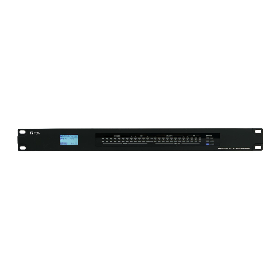
4. FRONT PANEL DESCRIPTION PEAK SIGNAL POWER 1. LC-Display It displays device information. Such as name, firmware and ID, and communication status. M-8080D (V2.6II) &0100 a. Displays device name and the firmware version. b. It displays the current preset. c. Current ID.The ID is automatically obtained when the device is correctly connected.ID&0100 d. -
Page 10: Rear Panel Description
5. REAR PANEL DESCRIPTION 1. Power Socket The power socket must be used with accessory cord. The supply voltage is between 100 V and 240 VAC, 50-60 Hz, depending on countries. The socket includes the fuse compartment. When changing it, make sure to replace it with a model of the same characteristics. - Page 11 Important Be sure to switch off the unit's power when connecting or removing the device. Failure to do so may cause the device to fail. 8. RELAY Dry contacts where ON/OFF status can be individually controlled in the System menu (Please refer to page 27).
-
Page 12: M-8080D Connection
6. M-8080D CONNECTION Standalone System M-8080D ROUTER Software Function Introduction Once the connection is completed. Open the M-8080D System Control Editor. The initial page shows as below: Click Enter to open the software. Attention: 1) After firmware is updated, the machine will automatically restart. After temporarily changing the router, it is recommended to restart the PC control software. - Page 13 2. Add Device Introduction Click "Scan", the system will automatically search for all online devices and appear in the matrix system list. Click the found matrix system, and select "Yes" in the pop-up window to connect to this system. Refresh: Refresh the current online status of the device.
- Page 14 System With Dante Module (M-8080D can only be enabled after the Dante module M-800DT is installed.) M-8080D ID: 0100 PRIMARY SECONDARY RD IN RD EXP ACT/LINK 1G ACT/LINK DANTE MODULE M-800DT M-8080D ID: 1600 PRIMARY SECONDARY RD IN RD EXP ACT/LINK 1G ACT/LINK DANTE MODULE M-800DT...
- Page 15 2. Add Device Introduction Click "Scan", the system will automatically search for all online devices and appear in the matrix system list. Click the desired matrix system, and select "Yes" in the pop-up window to connect to this system. Refresh: Refresh the current online status of the device. Note: The device information shows the information for the highlighted device.
-
Page 16: Dante Input Configure
7. DANTE INPUT CONFIGURE Configuration is only required if the Dante module M-800DT is installed and the "System with Dante module" mode is selected. Click "Dante Input Config" page to enter the configuration. 1. Dante Receivers: All online Dante devices are displayed below. 2. -
Page 17: Software Editor
8. SOFTWARE EDITOR Click "Device Config" page to enter the configuration. 8.1. INPUT DSP CHANNEL On the "DSP channel" page, click the input channel name to enter the corresponding input channel DSP settings. 12 11 1. EXP/Gate: The gate attenuates signals below the threshold value, and allows signals above the threshold value to pass. - Page 18 7. Bypass: The signal is not processed and skips to the next processing module. 8. Flat: All parameters are reset to the factory settings. 9. Comp: A compressor can limit the dynamics of a signal beyond a certain level. When the signal exceeds the Threshold it is compressed in a ratio greater than 1.
-
Page 19: Output Dsp Channel
8.2. OUTPUT DSP CHANNEL On the "DSP channel" page, click the output channel name to enter the corresponding output channel DSP settings. Same menu as the Input DSP Channel ,without the Expander/Gate section. The parametric EQ features 8 bands here, instead of 5 bands for the inputs. Please refer to the introduction of Input DSP Channel. Function Example: Adjust the high-pass filter / EQ point to the corresponding parameter, which is the same as Input DSP. -
Page 20: Matrix
8.3. MATRIX This part of the software is used to route inputs through a graphical representation as a matrix. By clicking on the gray boxes several inputs can be assigned to several outputs. If the connection is active the box turns green, otherwise it remains gray. -
Page 21: Ducker
8.4. DUCKER The principle of the Ducker is to attenuate one or several channels when priority signals are activated. The main applications are automatic speech for conference or priority messages. E.g. use the host microphone signal to control the background music volume. The host automatically reduces the background music volume when speaking. -
Page 22: Fbc (Feedback Compression)
8.5. FBC (FEEDBACK COMPRESSION) FBC (Feedback compression) function can effectively suppress howling expansion volume, ensure voice transmission quality, high fidelity, and clear sound. The dynamic filter and the static filter have the same function. They remove unwanted components or features from a signal in a certain frequency range. - Page 23 Function Example: Turn on local input / output 1. The corresponding input signal is sent to the FBC module for processing, and the corresponding button is lit to output the signal after FBC processing to the corresponding output channel. Click "Static Filter Setting" to enter the static filter setting mode. Set the volume of all input channels to the required level and turn on the microphone.
-
Page 24: Auto Mixer
8.6. AUTO MIXER The Auto mixer automatically controls the gains of multiple microphones in real time, dramatically reducing feedback, noise and comb-filtering from adjacent microphones. It maintains a consistent system gain, even when multiple speakers are talking simultaneously, and makes perfectly matched crossfades, without any signal compression. -
Page 25: Save / Load / Copy
8.7. SAVE / LOAD / COPY This menu is used to manage the backup parameters. These data can be stored directly in the internal memory of host as a preset. Its memory contains a total of 16 presets. 1. Import All Preset: Import all preset types from device to computer file. 2. - Page 26 Function Example 1: Save current preset to device 1) Select Device and click Save button. 2) Enter the preset name in the pop-up window. 3) Click Submit button to save the preset. Note: The preset list is saved separately and are not included in the system saving. Function Example 2: Select the input channel IN01 to copy to CH03.
-
Page 27: System
8.8. SYSTEM 1. Relay Control: Either IN01-IN08 or Paging (M-800RM) can be selected. When there is a broadcast signal on the selected channel, the corresponding relay terminal on the rear panel of the M-8080D will make contact and can be used to control the start-up/shutdown of external devices. 2. - Page 28 GPI Control Mode 1: Input Priority a. Priority Input Setting: Select input 1-8 for priority control. b. Output gain for priority: It used to control the output gain of the priority channel. GPI Control Mode 2: Mute All Outputs GPI Control Mode 3: Emergency Priority Emergency Priority is only used for emergency broadcast.
- Page 29 Output Zones Setting f. Output channel selection area: Select the corresponding output channel, green is selected, gray is not selected. g. Select All: Select all output channels. h. Clear All: Cancels all selected output channels. i. Save to Device: After selection, this button must be clicked to save the settings to the device to take effect. j.
- Page 30 Function Example 2: 1) According to the method described earlier, insert one end of the network cable into the GPI 1 port on the rear panel of the machine, and the other end is short-circuited. 2) The GPI 1 port on the PC software lights up to indicate that this function is enabled. 3) According to the set input priority and the selected IN01.
-
Page 31: Remote Devices
9. REMOTE DEVICES M-8080D offers a large choice of devices for volume adjustment, paging management, routing and IN/OUT modules. 9.1. M-800RM The M-800RM is a paging microphone and can address 1 to 12 different zones (outputs). A total of 2 x M-800RM can be used in a stand-alone system and a maximum of 32 x M-800RM in a Dante system, which makes a lot of possibilities for message paging. - Page 32 M-800RM Editor This function is a zone setting with audio routing function. You can control up to 12 output channels in a single zone. Distribute audio to different zones, and easily manage zones by adjusting the chime time / volume / priority.
-
Page 33: M-800Rc
16. Device Name: The default name is displayed in the box, click to modify the device name. 17. Save To Device: After the settings are modified, they need to be saved to the device to take effect. 18. Load from Device: Load presets from device to PC. 19. - Page 34 M-800RC Editor 1. Connect Status: When the signal light shows green, it means the communication status is normal. If it shows gray, it means no communication. 2. Select Input Channel to Control Volume: Selected is green, unselected is gray. 3. All Input Select: Select all input channels at once. 4.
-
Page 35: M-802Rc
9.3. M-802RC The M-802RC has the same functionality as the M-800RC volume control, but it includes 2 additional analog outputs. The device includes a build in D/A converter processing digital audio AES3 signals from M-8080D. M-802RC requires/consumes 2x digital output channels of in total 4 available digital output channels of M-8080D. - Page 36 M-802RC Editor 1. Connect Status: When the signal light shows green, it means the communication status is normal. If it shows gray, it means no communication. 2. Select Input Channel to Control Volume: Selected is green, unselected is gray. 3. All Input Select: Select all input channels at once. 4.
-
Page 37: M-822Io
9.4. M-822IO The M-822IO is a remote audio input and output module providing 2 x analog channels IN and 2 x analog channels OUT. The device includes build in A/D and D/A converters processing digital audio AES3 signals from and to the M-8080D. M-822IO requires/consumes 2x digital input + 2x digital ouptut channels. -
Page 38: M-800Rct
M-822IO Editor 1. Connect Status: When the signal light shows green, it means the communication status is normal. If it shows gray, it means no communication. 2. Device Name: The default name is displayed in the box, click to modify the device name. 3. - Page 39 Wall installation instructions: 1. First unscrew the screw on the bottom of the device with a screwdriver. 2. Fix the rear panel to the wall. Screw both ends to the wall. Check for firmness or crooked nails. 3. Insert the distributed network cable into the RD IN port, and snap the device to the rear panel. Tighten the bottom with screws.
- Page 40 The Preset menu can call up setting presets memorized in the M-8080D. 1. PRESET LIST: All the presets on the M-8080D are displayed here. 2. UP: Page up. 3. DOWN: Page down. 4. LOAD: After selecting a preset (1) click to load the preset. 5.
- Page 41 8. Select Output Channel to Control Volume: Selected is green, unselected is gray. 9. All Output Select: Select all output channels at once. 10. Output Channel Name: The default name is displayed in the box, click to modify the output channel name.
-
Page 42: M-804Ex
9.6. M-804EX The M-804EX is a port expander featuring a star connection of the controllers. This interface is particularly useful when daisy chain between devices is not possible or when the controllers are far away from the M-8080D. a. 24V DC power supply When there are too many devices connected to the RD EXP port of M-804EX and the POWER LED on the front panel of M-804EX is off, please connect an DC24V external power supply. -
Page 43: Application Examples
10. APPLICATION EXAMPLES RETAIL STORE More floors can also be easily expanded with the Dante system. SECOND FLOOR Sales Floor F-2000BT / WT MD-200CTU M-800RM M-8080D Fitting Room F-2352C PRIMARY SECONDARY RD IN RD EXP ACT/LINK 1G ACT/LINK DANTE MODULE M-800DT Stock Room F-2352C M-800RC... - Page 44 MALL Control up to 12 independent zones with a single M-8080D EV-20R MD-200CTU M-800RM M-8080D feeds 2 x 4 analog inputs of amplifiers. Each amplifier offers 4 individual lines of high impedance speakers to M-8080D broadcast BGM program , live paging and pre-recorded announcement in separate zones.
- Page 45 RESTAURANT / BAR Lobby Video Player Easy and quick volume control for operators MD-200CTU M-800RCT M-800RM 4 analog outputs of M-8080D BS-P1030BIP1 / WIP1 are used for 4 separate zones with volume controlled from the lobby. Two additional line out come M-8080D from the M-802RC remote controller using digital...
- Page 46 Lobby Flexible sound control BS-1034W M-800RCT Volume "and presets" can MD-200CTU M-800RM be controlled from the lobby by touch panel remote controller M-800RCT. In Aerobics Rooms, instructors can play M-8080D dedicated music via Music player connected to M-822lO input/output. Volume is controlled with M-804EX DA-250FH a specific M-800RC device.
-
Page 47: Appendix
11. APPENDIX RS232 codes Start Start Start Length Device Type Command Channel Local Channel : 0x 01 - 0x0C Value End Byte Byte0 Byte1 Byte2 ID Adress (High Byte) ID Adress (Low Byte) function (2 Byte) (2 Byte) (2 Byte) (2 Byte) (n Byte) Network Channel : 0x0D - 0x14... -
Page 48: Specifications
12. SPECIFICATIONS 12.1. 8x8 DIGITAL MATRIX MIXER M-8080D Power Source 100-240 V AC, 50/60 Hz Power Consumption 40 W Audio Input Input 1 - 8 : -48 to 0 dBV, 6.8 kΩ, electronic balanced, removable terminal block (3 pins x 8) Audio Output Output 1 - 8 : 0 dBV, 1.8 kΩ, Maximum output 20 dBu(7.75V), electronic balanced, removable terminal block (3 pins x 8) -
Page 49: Remote Microphone M-800Rm
12.2. REMOTE MICROPHONE M-800RM Power Source 24V DC (Powered by M-8080D or M-804EX) Audio Output 0 dBV, electronic balanced, RJ45 Connector Gooseneck Microphone Unidirectional electret condenser microphone Frequency Response 20 - 20,000 Hz, ±3 dB Total Harmonic Distortion 0.01 % RD port Transmits and receives AES3 digital audio plus control data cable length is 100 meters, Connect to M-8080D or M-804EX, RJ45 Connector... -
Page 50: Remote Audio Control Panel M-800Rc
12.3. REMOTE AUDIO CONTROL PANEL M-800RC Model no. M-800RC M-800RCB Power Source 24V DC (Powered by M-8080D or M-804EX) RD IN Transmits and receives AES3 digital audio plus control data Connect to M-8080D, M-804EX, M-800RCT or M-800RC for daisy chain, RJ45 Connector RD EXP Transmits and receives control data Connect to M-800RC, M-802RC or M-822IO, RJ45 Connector... -
Page 51: Remote Audio Input Output Panel M-822Io
12.5. REMOTE AUDIO INPUT OUTPUT PANEL M-822IO Model no. M-822IO M-822IOB Power Source 24V DC (Powered by M-8080D or M-804EX) Audio Input MIC input : -48 dBV, 5.1 kΩ, electronic balanced, XLR connector Line input A - B : 0 dBV, 5.1 kΩ, unbalanced, RCA pin jack Audio Output Line output 1 - 2 : 0 dBV, 1.8 kΩ... -
Page 52: Extension Module 4 Ports M-804Ex
12.7. EXTENSION MODULE 4 PORTS M-804EX Power Source 24V DC (Powered by M-8080D or DC24V external power supply) RD IN Transmits and receives AES3 digital audio plus control data Connect to M-8080D, RJ45 Connector RD EXP Port 1: transmits and receives AES3 digital audio plus control data connect to M-800RM, M-800RCT, M-800RC, M-802RC or M-822IO, RJ45 Connector maximum cable length 100 meters in total from M-8080D RD port to last controller Port 2-4: transmits and receives control data... -
Page 53: Arabic Important Safety Instructions
13. ARABIC IMPORTANT SAFETY INSTRUCTIONS... - Page 56 7-2-1, Minatojima-Nakamachi, Chuo-ku, Kobe, Hyogo, Japan Traceability Information for Europe Traceability Information for Americas Authorized representative: Authorized representative: TOA Electronics Europe GmbH TOA Electronics, Inc. Suederstrasse 282, 20537 Hamburg, 1 Harmon Plaza, Suite 700 Secaucus, Germany New Jersey 07094, USA TEL: +1 650 452 1200 URL: https://www.toa.jp/...
Need help?
Do you have a question about the M-8080D Series and is the answer not in the manual?
Questions and answers