Toa M-8080D Series Operating Instructions Manual
Digital matrix mixer system
Hide thumbs
Also See for M-8080D Series:
- Operating instructions manual (56 pages) ,
- Firmware update manual (9 pages) ,
- Operating instructions manual (56 pages)
Table of Contents
Advertisement
Quick Links
Advertisement
Table of Contents

Related Manuals for Toa M-8080D Series


Summary of Contents for Toa M-8080D Series
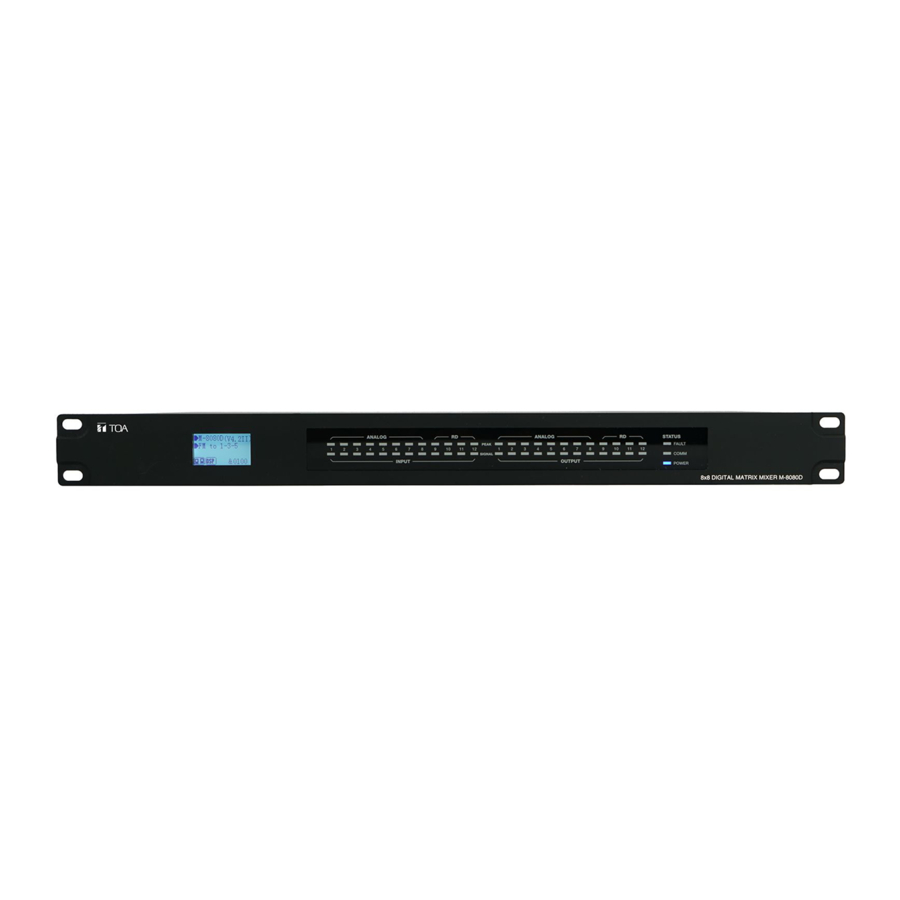
- Page 1 OPERATING INSTRUCTIONS DIGITAL MATRIX MIXER SYSTEM M-8080D SERIES PEAK SIGNAL POWER Thank you for purchasing TOA's Digital Matrix Mixer System. Please carefully follow the instructions in this manual to ensure long, trouble-free use of your equipment.
-
Page 2: Table Of Contents
TABLE OF CONTENTS 1. IMPORTANT SAFETY INSTRUCTIONS 2. INTRODUCTION 3. MAIN FEATURES 3.1. DIGITAL MATRIX 3.2. DSP FUNCTIONS 3.3. NETWORKS 4. FRONT PANEL DESCRIPTION 5. REAR PANEL DESCRIPTION 6. M-8080D CONNECTION 7. SOFTWARE EDITOR 7.1. INPUT DSP CHANNEL 7.2. MATRIX 7.3. -
Page 3: Important Safety Instructions
IMPORTANT SAFETY INSTRUCTIONS • Read these instructions. • Keep these instructions. • Heed all warnings. • Follow all instructions. • Do not use this apparatus near water. • Clean only with dry cloth. • Do not block any ventilation openings. Install in accordance with the manufacturer's instructions. •... - Page 4 Should the following irregularity be found during use, immediately switch off the power, disconnect the power supply plug from the AC outlet and contact your nearest TOA dealer. Make no further attempt to operate the unit in this condition as this may cause fire or electric shock.
- Page 5 Indicates a potentially hazardous situation which, if mishandled, could CAUTION result in moderate or minor personal injury, and/or property damage. When Installing the Unit • Never plug in nor remove the power supply plug with wet hands, as doing so may cause electric shock. •...
-
Page 6: Introduction
2. INTRODUCTION Thank you for purchasing the M-8080D series Digital Matrix Mixer System. This device is dedicated to music, paging, discussion and zone management solutions for Commercial Audio applications. Easy to use and to implement, M-8080D offers state-of-the-art signal processing in a cost effective package. -
Page 7: Dsp Functions
3.2. DSP FUNCTIONS M-8080D is intended for non-experts. The system used fix architecture for quick and easy operation. The intuitive GUI utilizes a familiar hardware-like layout to enable a short programming timeline and rapid hardware implementation. All functions can be configured with the PC Editor Software. Settings can be memorized for easy duplication or modification: 3.3. - Page 8 The green pair is reserved for data communications between M-8080D and remote device. Data communication is needed to send configuration information, software update and status information from M-8080D to remote device. Note: Configuration information of remote device (such LED illuminate status, microphone sensitivity, channel name, etc.) is stored in M-8080D, not in the remote devices.
-
Page 9: Front Panel Description
4. FRONT PANEL DESCRIPTION PEAK SIGNAL POWER 1. LC-Display It displays device information. Such as name, firmware and ID. And communication status. M-8080D (V2.6II) &0100 a. Displays device name and the firmware version. b. It displays the current preset. c. Current ID.The ID is automatically obtained when the device is correctly connected.ID&0100 d. -
Page 10: Rear Panel Description
6. STATUS • FAULT Red LED indicating a malfunction of the DSP. The information is relayed on the LC-Display. • COMM Green LED indicating the communication status between the PC and the device. The LED blinks during data transfer. It remains off in case of problems. •... - Page 11 5. ON/OFF SW Switch on assign Ethernet to the LAN port . 6. RD 9/10 RD Port to connect remote device accessory such as M-822IO, M-802RC, M-800RM, M-800RC, M-800RCT and M-804EX. This port transmits and receives AES3 digital audio plus control data. M-822IO for instance, includes A/D and D/A converters for two I/O assigned to channels 9 and 10.
-
Page 12: M-8080D Connection
Save As: Save current preset to local, Press this button to save all current presets (except the preset list data). Config Device ID: Customize device ID. The ID shall be always "0100" . Offline Load: Only for TOA technicians to offline analyze whether the user preset files are correct. Offline Save: Only for TOA technicians after offline editing, save preset to local. - Page 13 There are 7 kinds of machine in the Matrix system. You can select any device to input ID to view this device parameter (like Demo ). Attention: M-8080D: The device can only enter 4 digits (ID with last two digits 0 and less than 8100). M-800RM / M-822IO / M-802RC: The device can only enter 4 digits (The last two digits are 50, 60, 90, A0, B0, C0, D0, E0, and less than 81E0 ).
- Page 14 3. Generate Code When performing any function operation, press this button and the corresponding command will be displayed below the software. 4. Help Click the Help , a pop-up window will display the information of the current software.
-
Page 15: Software Editor
7. SOFTWARE EDITOR 7.1. INPUT DSP CHANNEL 1. EXP/Gate: The gate attenuates signals below the threshold value, and allows signals above the threshold value to pass. When the signal is beyond the threshold, the output signal remains identical to the input signal. By adjusting the value of the ratio to its maximum, the Expander is transformed into a Noise Gate. - Page 16 5. EQ: High Pass Filter and Low Pass Filter: Those filters are used to eliminate non necessary frequencies above and below the signal spectrum, in order to avoid any background noise generation due to multi-processing. For instance, a voice microphone will be set to 100Hz for the High Pass and 4kHz for the Low Pass.
-
Page 17: Matrix
Attention: In case of M-800RCT, the individual name setting is not transmitted automatically to the device. Use the seperate Setting page of M-800RCT for setting individual names to be transmitted and indicated on M-800RCT. Function Example: Adjusting the high-pass filter to 32.7Hz. Type is adjusted to BW24. Drag EQ1 to 54.4Hz and adjust the Q value to 2.0. -
Page 18: Output Dsp Channel
IN(OUT) 01 to IN(OUT) 08 are analog I/O available on the rear panel. In(OUT) 09 to IN(OUT) 12 are digital I/O (RD ports) and are converted to analog signals. Attention: After the M-800RM is connected, the corresponding output is automatically turned off . The purpose is to avoid: no broadcast but also has output. -
Page 19: Ducker
Function Example: Adjust the high-pass filter / EQ point to the corresponding parameter, which is the same as Input DSP. The waveform in the EQ diagram will also change accordingly. 7.4. DUCKER The principle of the Ducker is to attenuate one or several channels when priority signals are activated. The main applications are automatic speech for conference or priority messages. -
Page 20: Fbc (Feedback Compression)
2. Ducker Parameter Setting Threshold: threshold of attenuation. From 0dB to -80dB. Depth: depth of attenuation. Activation Time: Velocity of gain change to attenuate inputs. BYPASS: The signal is not processed and skips to the next processing module. Function Example: The current setting sets channel 1 to level 1, channel 2 to level 2, and channel 3 to level 3. - Page 21 FBC (Feedback compression) function can effectively suppress howling expansion volume, ensure voice transmission quality, high fidelity, and clear sound. The dynamic filter and the static filter function the same. Used to remove devices above or below a certain frequency. To increase or decrease a range of frequencies in sound by passing them through. The differences between them are: 1.
-
Page 22: Auto Mixer
Function Example: Turn on local input / output 1. The corresponding input signal is sent to the FBC module for processing, and the corresponding button is lit to output the signal after FBC processing to the corresponding output channel. Click "Static Filter Setting" to enter the static filter setting mode. Set the volume of all input channels to the required level and turn on the microphone. -
Page 23: Save / Load / Copy
Source Select Local Input: selection of input channels (1-12) to be processed. Activation Time Set the start mixing time of the signal of the selected input channel. Push ON to activate the time setting, and use the horizontal fader to set the time value. Function Example: Add the local input CH 1 and CH2 open setting to the automatic mixing function. - Page 24 This menu is used to manage the backup parameters. These data can be stored directly in the internal memory of host as a preset. Its memory contains a total of 16 presets. 1. Import All Preset: Import all preset types from device to computer file. 2.
-
Page 25: System
Save current preset to device 1) Select Device and click Save button. 2) Enter the preset name in the pop-up window. 3) Click Submit button to save the preset. Note:The preset list are saved separately and are not included in the system saving. Function Example 2: Select the input channel Input1 to copy to CH03. - Page 26 1. Relay Control: It is used to control external devices. Allow end users to control their actions. 2. Password Setting: Press this button to modify the password. 3. Lock System: Press this button to lock the system. It is locked at this time, you need to enter the password to unlock, if you forget the password, you can use the super password MA88 to unlock.
- Page 27 Function Example 1: Click Password Setting, enter the current password and the password you want to modify, click Confirm, the password will be successfully modified. Function Example 2: 1) According to the method described earlier, insert one end of the network cable into the GPI 1 port on the rear panel of the machine, and the other end is short-circuited.
-
Page 28: Remote Devices
8. REMOTE DEVICES M-8080D offers a large choice of devices for volume adjustment, paging management, routing and I/O modules. 8.1. M-800RM The M-800RM is a Paging Microphone and can address 1 to 12 different zones (outputs). Moreover, a total of 2 x M-800RM can be used in a system, which makes a lot of possibilities for message paging. - Page 29 g. XLR connector Female 3 pin XLR connector for the gooseneck electret microphone. It uses a phantom power controlled by software. h. USB port This port is used to load WAV / MP3 files for chimes sound. The maximum time for the chimes is 4 seconds.
- Page 30 This function is a partition setting, with audio routing function, can control up to 12 partitions. Distribute audio to different partitions, and easily manage partitions by adjusting the sending time / volume / priority. 1. Connect Status: When the signal light shows green, it means the communication status is normal. If it shows gray, it means no communication.
-
Page 31: M-800Rc
8.2. M-800RC This volume controller can be assigned to any output of the M-8080D. It can also route any input to any output like in the Matrix menu of the Editor Software. a. LC-Display It displays the volume level and the signal level for a dedicated output. - Page 32 M-800RC Editor 1. Select Channel to Control Volume -Input Channel 1 - 12: Check the box to control the input of multiple channels at once. -Output Channel 1 - 12: Check the box to control the output of multiple channels at once. 2.
-
Page 33: M-802Rc
8.3. M-802RC The M-802RC has the same functionality as the M-800RC volume control, but it includes 2 additional analog outputs. The device includes a build in D/A converter processing digital audio AES3 signals from M-8080D M-802RC requires/consumes 2x digital output channels of in total 4 available digital output channels of M-8080D. - Page 34 M-802RC Editor 1. Select Channel to Control Volume: -Input Channel: Check the box to control the input of multiple channels at once. -Output Channel: Check the box to control the input of multiple channels at once. 2. Enable Routing Function -Output Channel 1 - 12: Check the box to control the routing of multiple output channels at once.
-
Page 35: M-822Io
8.4. M-822IO The M-822IO is a remote audio input and output module providing 2 x analog channels IN and 2 x analog channels OUT. The device includes build in A/D and D/A converters processing digital audio M-8080D. AES3 signals from and to the M-822IO requires/consumes 2x digital input + 2x digital ouptut channels. -
Page 36: M-800Rct
Wall installation instructions: 1. First unscrew the screw on the bottom of the device with a screwdriver. 2. Fix the back plate to the wall. Screw both ends to the wall. Check for firmness or crooked nails. 3. Insert the distributed network cable into the RD IN port, Connect the analog output cable, and snap the device to the back plate. - Page 37 Attention: 1 ) M-800RM / M-822IO / M-802RC (with audio transmission) can only be connected to the RD port of the M-8080D or the RD EXP port 1 of M-804EX. 2 ) M-800RC / M-800RCT (with control function) can link each other. Wall installation instructions: 1.
- Page 38 In the Output section, the routing function can assign any input to any output. Volume and mute can be adjusted and visually monitored. 1 ) Mute: Click this button, the selected current output channel will be muted. 2 ) Output 01 - Output 12: Switch the setting interface of OUT 01 - OUT 12. 3 ) Input 01 - Input 12: Turn on / off input channels 01 - 12.
- Page 39 M-800RCT Editor 1. Select Channel to control volume: -Input Channel 1 - 12: Check the box to control the input of multiple channels at once. -Output Channel 1 - 12: Check the box to control the output of multiple channels at once. 2.
-
Page 40: M-804Ex
7. Save to Device: Save the current parameters to the device. 8. Default: Restore initialization parameters. 9. Load From PC: Load presets from local PC. 10. Save To PC: Save the current preset parameters to the local PC. 11. Screen Saver: After checking this box, the machine will sleep after one minute of inactivity. Note: The factory setting is ON. -
Page 41: Application Examples
9. APPLICATION EXAMPLES RETAIL STORE Sales Floor Simple installation with F-2000BT / WT ambiance control MD-200CTU M-800RM The 4 zone volumes are individually controlled from the office or from the counter with stereo or mono signals. M-8080D A free Soundcard Output of Fitting Room F-2352C PC can be connected to... - Page 42 MALL Control up to 12 independent zones with a single M-8080D EV-20R MD-200CTU M-800RM M-8080D feeds 2 x 4 analog inputs of amplifiers. Each amplifier offers 4 individual lines of high impedance speakers to M-8080D broadcast BGM program , live paging and pre-recorded announcement in separate zones.
- Page 43 RESTAURANT / BAR Lobby Video Player Easy and quick volume control for operators MD-200CTU M-800RCT M-800RM 4 analog outputs of M-8080D BS-P1030BIP1 / WIP1 are used for 4 separate zones with volume controlled from the lobby. Two additional line out come M-8080D from the M-802RC remote controller using digital...
-
Page 44: Appendix
10. APPENDIX Start Start Start Length Device Type Command Channel Local Channel : 0x 01 - 0x0C Value End Byte Byte0 Byte1 Byte2 ID Adress (High Byte) ID Adress (Low Byte) function (2 Byte) (2 Byte) (2 Byte) (2 Byte) (n Byte) Network Channel : 0x0D - 0x14 (n Byte) -
Page 45: Specifications
11. SPECIFICATIONS 11.1. 8x8 DIGITAL MATRIX MIXER M-8080D Power Source 100-240 V AC, 50/60 Hz Power Consumption 40 W Input 1 - 8 : -48 to 0 dBV, 6.8 k Ω , electronic balanced, Audio Input removable terminal block (3 pins x 8) Output 1 - 8 : 0 dBV, 1.8 k Ω... -
Page 46: Remote Microphone M-800Rm
11.2. REMOTE MICROPHONE M-800RM Power Source 24V DC (Powered by M-8080D or M-804EX) Audio Output 0 dBV, electronic balanced, RJ45 Connector Gooseneck Microphone Unidirectional electret condenser microphone Frequency Response 20 - 20,000 Hz, ±3 dB Total Harmonic Distortion 0.01 % RD port Transmits and receives AES3 digital audio plus control data Connect to M-8080D or M-804EX, RJ45 Connector... -
Page 47: Remote Audio Control Panel With Audio Out M-802Rc
11.4. REMOTE AUDIO CONTROL PANEL WITH AUDIO OUT M-802RC Model no. M-802RC M-802RCB Power Source 24V DC (Powered by M-8080D or M-804EX) Line output 1 - 2 : 0 dBV, 1.8 k Ω, Maximum output 20 dBu (7.75 V) , Audio Output electronic balanced, screw terminal (3 pins x 2) RD IN... -
Page 48: Remote Audio Control Panel With Touch Display M-800Rct 3
11.6. REMOTE AUDIO CONTROL PANEL WITH TOUCH DISPLAY M-800RCT Model no. M-800RCT M-800RCTB Power Source 24V DC (Powered by M-8080D or M-804EX) RD IN Transmits and receives AES3 digital audio plus control data Connect to M-8080D, M-804EX or M-800RC, M-800RCT for daisy chain, RJ45 Connector RD EXP Transmits and receives control data Connect to M-800RC or M-800RCT, RJ45 Connector... - Page 52 7-2-1, Minatojima-Nakamachi, Chuo-ku, Kobe, Hyogo, Japan Traceability Information for Europe Traceability Information for Americas Authorized representative: Authorized representative: TOA Electronics Europe GmbH TOA Electronics, Inc. Suederstrasse 282, 20537 Hamburg, 1 Harmon Plaza, Suite 602 Secaucus, Germany New Jersey 07094, USA TEL: +1 650 452 1200 URL: http://www.toa.jp/...
Need help?
Do you have a question about the M-8080D Series and is the answer not in the manual?
Questions and answers