
Related Manuals for Toa D-4E


Summary of Contents for Toa D-4E
- Page 1 Operating Instruction Manual ELECTRONIC MUSIC MIXER Model D-4, D-4E D-4E Toa Electric Co., Ltd. KOBE JAPAN...
-
Page 2: Table Of Contents
The connectors are wired as follows. The pin 1 is ground (shield), the pin 2 cold (low, minus), the pin 3 hot (high, plus). 2. Description of components and functions on the D-4, D-4E Various descriptions are applied, depending on each manufacturer. In our Operating and Instruction Manual explanation of components and functions is made according to our usage for them. -
Page 3: General Description
XLR inputs, each with its own 48 volt phantom power when combined with the D-4 give a total of eight MIDI Thru jacks. The D-4E features a buss link jack located on the back panel to connect it to the D-4, with the included 2-foot buss-connect cord (a 6-foot connecting cord is optional —... -
Page 4: Features
7. Direct output on each channel, ideal for recording 8. Concentric stereo pan and channel volume control 9. Input Channel 4 on D-4 has electronically balanced XLR input connector with switchable 48 volt phantom power, as do Channels 5, 6, 7, and 8 on D-4E - 3 -... -
Page 5: Front Panel: Names Of Components & Their Usage [D-4]
Front Panel (D-4) Effects Control (EFF) Writing Block This control determines the The name of the input equipment can be written in with an erasable amount of post-fader/post-EQ sig- felt pen or grease pencil. nal assigned to the effect buss from a given input channel, and thus the level of effects for that channel. -
Page 6: Rear Panel: Names Of Components & Their Usage [D-4]
MIDI Thru connectors on the connecting the D-4's XLR Sum Out- D-4E, if used. Each of the MIDI Thru put with other equipment. Sliding jacks can be connected to a different the Ground Lift Switch from the... -
Page 7: Front Panel [D-4E]
MIDI Thru connectors on the D-4, and to four more MIDI Thru connectors on the D-4E, if used. Each of the MIDI Thru jacks can be connected to a different synthesizer's MIDI input jack, allow- ing one MIDI keyboard or sequencer to control up to four other MIDI synths (eight when using the D-4E.) -
Page 8: Block And Level Diagrams
Block and Level Diagrams BLOCK DIAGRAMS LEVEL DIAGRAM D-4E BLOCK DIAGRAMS LEVEL DIAGRAM - 7 -... -
Page 9: Specifications [D-4, D-4E]
CH1 ~ CH4 <CH5 ~ CH10> ACCESSORY OUT (INPUT STEREO SUM) PHONES < > : D-4E ONLY All XLR type connectors are electronically balanced. Stereo phone jack is wired: Tip=Left, Ring=Right and Sleave=Common –100dB* –85dB* (D-4 ONLY) –82dB* (D-4E CONNECTION) –78dB* (S/N 82dB) -
Page 10: Procedure For Changing Internal Switch Settings
Procedure for changing internal switch setting NOTE: The internal switches have been provided for added versatility when using the D-4 and D-4E in a variety of applications. 1. ACCESSORY PATCH SELECT SWITCH: Each input features an internal accessory "loop" (in/out) for in-line... -
Page 11: Characteristics Diagrams
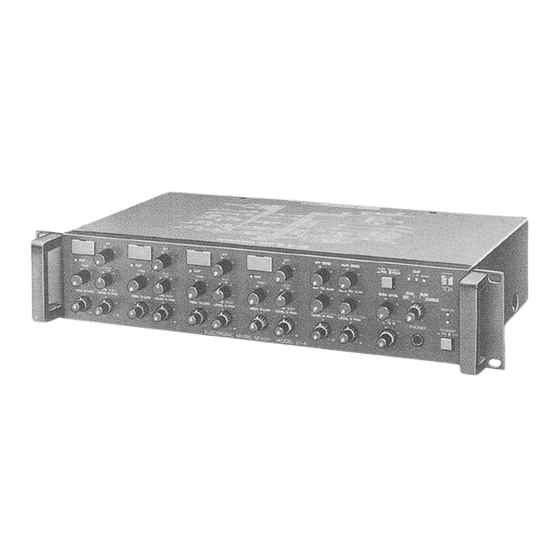
Characteristics Diagrams INPUT EQ CHARACTERISTICS FREQUENCY RESPONSE Frequency Frequency Appearance D-4E - 10 -... - Page 12 Printed in Japan 133-02-727-70...
Need help?
Do you have a question about the D-4E and is the answer not in the manual?
Questions and answers