Table of Contents
Advertisement
Quick Links
General Information
Installation Information
Controls & Operation
Sealed System
Air Flow & Fan Blade Spacing
Icemaker Information
Troubleshooting Guide
Technical Data
LOKRING Information
Wiring Diagrams
ICB 700 Base
Service Manual
subzero.com
800.222.7820
33
39
41
68
85
88
89
2
5
7
Advertisement
Table of Contents

Subscribe to Our Youtube Channel
Related Manuals for Sub-Zero Wolf ICB700 Series


Summary of Contents for Sub-Zero Wolf ICB700 Series
- Page 1 subzero.com 800.222.7820 ICB 700 Base Service Manual General Information Installation Information Controls & Operation Sealed System Air Flow & Fan Blade Spacing Icemaker Information Troubleshooting Guide Technical Data LOKRING Information Wiring Diagrams...
- Page 2 Technicians. The information and images contained in this manual are the copyright property of Sub-Zero, Inc. Neither this man- ual nor any information or images contained herein may be copied or used in whole or in part without the express written consent of Sub-Zero, Inc.
- Page 3 For this reason the model and serial number may be important information. See Serial Tag Layout diagram below. Note: The serial number tag is located on the left wall of the upper drawer compartment. Model Number Serial Number Manufacture Date SUB-ZERO, INC. MADISON, WISCONSIN MADE IN THE USA MODEL SERIAL NUMBER VOLTAGE ICB700BCI...
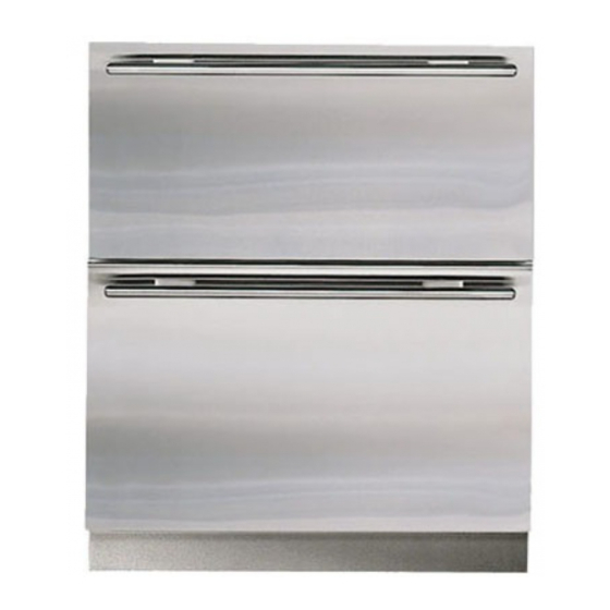
- Page 4 International Integrated Series International Integrated Series General Information (ICB700 Base) (ICB700 Base) MODEL DESCRIPTIONS This page briefly describes the Models ICB700BCI, ICB700BFI and ICB700BR. Model ICB700BCI (Figure 1-2) nternational Approved Series, Upper ombination, cemaker Incl. Refrigerator Zone (Combination Refrigerator / Freezer with Two Temperature Zones - Upper Refrigerator over Freezer) Lower Freezer...
- Page 5 NOTE: If additional installation information is needed, refer to the complete Installation Manual and/or installation video, or contact the Sub-Zero Technical Assistance Department. UNIT COULD TIP FORWARD UNDER CERTAIN LOAD CONDITIONS. FAILURE TO INSTALL ANTI-TIP COM- PONENTS AND EXTEND LEVELERS TO THE FLOOR ACCORDING TO INSTALLATION MANUAL COULD RESULT IN SERIOUS PERSONAL INJURY OR DEATH.
- Page 6 International Integrated Series International Integrated Series Installation Information (ICB700 Base) (ICB700 Base) Rear levelers are adjusted at front of base by turning Phillips head adjusting rod, which engages rear leveler assembly. Turn rod clockwise to raise rear or counter- clockwise to lower it (See Figure 2-4).
- Page 7 International Integrated Series International Integrated Series Electronic Control System (ICB700 Base) (ICB700 Base) ELECTRONIC CONTROL TERMINOLOGY & COMPONENT DESCRIPTIONS All ICB700 Series units utilize an electronic control system which monitors, regulates, controls and displays a variety of functions and operations in the appliance. The table below defines some of the basic electronic control system terminology.
- Page 8 International Integrated Series International Integrated Series Electronic Control System (ICB700 Base) (ICB700 Base) ELECTRONIC CONTROL SYSTEM OVERVIEW This page contains the wiring schematic of the model ICB700BCI. Input operations for the electronic control system are performed at the control panel (located inside the upper drawer), with monitoring, regulating and controlling func- tions taking place at the main control board.
- Page 9 International Integrated Series International Integrated Series Electronic Control System (ICB700 Base) (ICB700 Base) MAIN CONTROL BOARD LAYOUT AND SUMMARY TABLE Electrical connection points on the main control board are labeled alphanumerically. These labels correspond with the alphanumeric summary table, located on the wiring diagram. By referencing the summary table, it is possible to identify which components are connected at which points on the main control board.
- Page 10 International Integrated Series International Integrated Series Electronic Control System (ICB700 Base) (ICB700 Base) CONTROL PANEL LAYOUT NOTE: The LCD on the base units is not back lit. It will appear darker than the LCD on tall units. REFRIGERATOR SET-POINT DRAWER AJAR (Liquid Crystal Display) ADJUSTMENT KEYS ALARM ON/OFF KEY...
- Page 11 International Integrated Series International Integrated Series Electronic Control System (ICB700 Base) (ICB700 Base) BASIC ELECTRONIC CONTROL INPUT OPERATIONS The following pages describe the basic input operations performed at A ICB700BCI control panel (switching unit ON and OFF; adjusting set-point (temperature adjustment); switching ice maker system ON and OFF and enabling and disabling door ajar alarm feature.
- Page 12 International Integrated Series International Integrated Series Electronic Control System (ICB700 Base) (ICB700 Base) Icemaker System ON/OFF All units with icemakers are shipped with the icemaker system switched OFF. By pressing the ICE ON/OFF key on the control panel, power is allowed to the icemaker system, and “ICE” appears on the LCD (See Figure 3-9).
- Page 13 International Integrated Series International Integrated Series Electronic Control System (ICB700 Base) (ICB700 Base) UNIQUE ELECTRONIC CONTROL INPUT OPERATIONS The following pages describe unique electronic control input operations performed at the control panel that you would not expect a customer to perform every day. The following input operations described are Temperature Unit Selection Mode, Sabbath Mode, Showroom Mode, and Manual Freezer Evaporator Defrost.
- Page 14 International Integrated Series International Integrated Series Electronic Control System (ICB700 Base) (ICB700 Base) Showroom Mode Showroom Mode was incorporated into the electronic control system so that units could be displayed in a showroom setting. When in Showroom Mode, all cooling functions are disabled, but the lighting system and LCD remain active.
- Page 15 International Integrated Series International Integrated Series Electronic Control System (ICB700 Base) (ICB700 Base) FUNCTIONS OF ELECTRONIC CONTROL SYSTEM The following few pages explain monitoring, regulating and controlling functions of the electronic control system. Display Zone Temperatures The temperature signals from the thermistors in the refrigerator and freezer compartments are monitored by the microprocessor and then displayed on the LCD.
- Page 16 International Integrated Series International Integrated Series Electronic Control System (ICB700 Base) (ICB700 Base) Regulate Freezer Zone Temperature (ICB700BCI, ICB700BFI) When the thermistor in the freezer compartment reaches high off-set temperature, calling for cooling, the compres- sor and condenser fan are energized, but the evaporator fan is not allowed to run until the thermistor on the evapo- rator reaches 2°C (35°F).
- Page 17 International Integrated Series International Integrated Series Electronic Control System (ICB700 Base) (ICB700 Base) Regulate Refrigerator Zone Temperature (ICB700BCI) When the thermistor in refrigerator compartment reaches high off-set temperature, calling for cooling, the refrigerator compartment fan is energized and microprocessor sends an 18 Volt pulse signal to the air baffle control to open, regardless of operational state of the compressor.
- Page 18 International Integrated Series International Integrated Series Electronic Control System (ICB700 Base) (ICB700 Base) Regulate Refrigerator Zone Temperature (ICB700BR) When the thermistor in the refrigerator compartment reaches high off-set temperature, calling for cooling, the evapo- rator fan is energized, but the compressor and condenser fan are not allowed to run until the thermistor on the evap- orator reaches 3°C (38°F).
- Page 19 International Integrated Series International Integrated Series Electronic Control System (ICB700 Base) (ICB700 Base) Monitor and Control “Adaptive Defrost” (ICB700BCI, ICB700BFI) Initially, the compressor will cycle-run for 12 hours, after which the microprocessor sends a signal to the defrost relay on the control board to close. This supplies power to the defrost heater, drain tube heater and fill tube heater. At the same time the compressor, condenser fan and evaporator fan are switched off.
- Page 20 International Integrated Series International Integrated Series Electronic Control System (ICB700 Base) (ICB700 Base) Monitor and Control Refrigerator Fan-Assisted, Off-Cycle Defrost (ICB700BR) Temperature signals from refrigerator evaporator's thermistor’s are observed by the microprocessor. During off cycle defrost, if a refrigerator zone temperature reaches high offset (calling for cooling) before evaporator temperature rises to 3°C (38°F), no power will be supplied the the compressor.
- Page 21 International Integrated Series International Integrated Series Electronic Control System (ICB700 Base) (ICB700 Base) Monitor Compressor Run Duration, Displays If Service is Needed The microprocessor observes the state of the compressor relay to determine the length of compressor run time (See Figure 3-22).
- Page 22 International Integrated Series International Integrated Series Electronic Control System (ICB700 Base) (ICB700 Base) Monitor Icemaker System and Display If Service is Needed The microprocessor observes the power supplied to the icemaker water valve solenoid. If the solenoid is energized for more than 15 seconds, power to the icemaker system is disabled for 24 hours and an error code is logged (EC 30).
- Page 23 International Integrated Series International Integrated Series Electronic Control System (ICB700 Base) (ICB700 Base) POSSIBLE ERROR INDICATORS The diagrams on this page illustration what a customers may see on LCD if a problem/error exists with the unit. NOTE: To clear indicators and error codes, problem must be corrected then press bell ON/OFF key for 15 seconds. SERVICE SERVICE Figure 3-26.
- Page 24 International Integrated Series International Integrated Series Electronic Control System (ICB700 Base) (ICB700 Base) ELECTRONIC CONTROL TROUBLESHOOTING INPUT OPERATIONS The following few pages explain troubleshooting input operations performed at the control panel. The input opera- tions described are Diagnostic Mode, Manual Component Activation Mode and Temperature Log Recall. Diagnostic Mode Initiating Diagnostic Mode allows the Service Technician to observe real-time temperature readings from all thermis- tors without temperature averaging.
- Page 25 International Integrated Series International Integrated Series Electronic Control System (ICB700 Base) (ICB700 Base) Diagnostic Mode Indicators If “EE” is observed in left display area during Diagnostic Mode, the thermistor in that location is open or shorted, or there is a break in that thermistor’s wiring (See Figure 3-36).
- Page 26 International Integrated Series International Integrated Series Electronic Control System (ICB700 Base) (ICB700 Base) If Error Codes are observed in Diagnostic Mode, a non-flashing SERVICE icon will appear on the LCD when Diagnostic Mode ends, indicating error codes are still stored (See Figure 3-39).
- Page 27 International Integrated Series International Integrated Series Electronic Control System (ICB700 Base) (ICB700 Base) Temperature Log Recall Mode The electronic control system is equipped with a temperature history data storage system. This system logs/stores the average temperature of each individual thermistor every two hours, along with any event indicators (explained later in this section), that may have occurred.
- Page 28 International Integrated Series International Integrated Series Electronic Control System (ICB700 Base) (ICB700 Base) Initiate Temperature Log Recall Mode To View Compartment and Evaporator Temperature History - To view compartment and/or evaporator temperature history, begin with the unit ON and in Diagnostic Mode (See Figure 30- 46).
- Page 29 International Integrated Series International Integrated Series Electronic Control System (ICB700 Base) (ICB700 Base) Temperature Log Event Indicators The diagrams below illustrate possible event indicators that may be observed while in Temperature Log Recall Mode. (See Figures 3-50 through 3-52 Temperature Log Index Chart on next page)) Figure 3-52.
- Page 30 International Integrated Series International Integrated Series Electronic Control System (ICB700 Base) (ICB700 Base) Temperature Log Index Chart NOTE : The chart below applies to the hours in which the control has power. Temperature history data will only be stored when the control has 230 V AC supplied to it. If power to the unit is interrupted, the average temperatures for that time period are stored with the event indicator.
- Page 31 International Integrated Series International Integrated Series Electronic Control System (ICB700 Base) (ICB700 Base) ELECTRONIC CONTROL SERVICE INPUT OPERATIONS Model Configuration Mode The main control board is used in several different models, so when a ICB700 Base Unit is manufactured, the main control board must be configured/programmed for the specific model it is used in by a series of key strokes at the control panel.
- Page 32 International Integrated Series International Integrated Series Electronic Control System (ICB700 Base) (ICB700 Base) Manual Entry Model Configuration Mode Manual Entry Model Configuration Mode allows a Service Technician to verify a main control board in a ICB700 Base unit was configured correctly, and/or to reconfigure the main control board if a mistake was made during the configuration process.
- Page 33 International Integrated Series International Integrated Series Sealed System Information (ICB700 Base) (ICB700 Base) HFC-134a REFRIGERANT SERVICE INFORMATION The ICB700 Series sealed systems contain HFC-134a refrigerant. This section provides some general rules for working with 134a, and explains procedures to be followed while servicing the sealed system. This is followed by diagrams which illustrate sealed system operation, then model-specific refrigerant flow diagrams.
- Page 34 International Integrated Series International Integrated Series Sealed System Information (ICB700 Base) (ICB700 Base) SEALED SYSTEM REPAIR PROCEDURES Problem Service Procedures Non-Operating, Inefficient, Capture refrigerant Noisy Compressor Replace Compressor Replace filter-drier Evacuate or sweep charge system Recharge system with Virgin 134a refrigerant. NOTE: To check for a non-operating compressor, a hard start kit can be used.
- Page 35 International Integrated Series International Integrated Series Sealed System Information (ICB700 Base) (ICB700 Base) SEALED SYSTEM OPERATION The six diagrams on these pages illustrate a basic sealed system. The components are listed in order of refrigerant flow, with an explanation of their fundamental role as part of a sealed system.
- Page 36 International Integrated Series International Integrated Series Sealed System Information (ICB700 Base) (ICB700 Base) Capillary Tube (& Heat Exchanger) (Figure 4-4) The warm liquid refrigerant travels through the long skinny capillary tube which is soldered to the suction line. (These two (EVAPORATOR SUMP) tubes soldered together create the heat exchanger.) As the...
- Page 37 International Integrated Series International Integrated Series Sealed System Information (ICB700 Base) (ICB700 Base) SEALED SYSTEM REFRIGERANT FLOW DIAGRAM Heater Loop Evaporator Heat Exchanger Condenser Compressor High-Side Filter Drier Figure 4-1. Model ICB700BCI Refrigerant Flow Heater Loop Evaporator Heat Exchanger Condenser Compressor High-Side Filter Drier Figure 4-2.
- Page 38 International Integrated Series International Integrated Series Sealed System Information (ICB700 Base) (ICB700 Base) Heater Loop Evaporator Heat Exchanger Condenser Compressor High-Side Filter Drier Figure 4-3. Model ICB700BFI Refrigerant Flow 7011902 - Revision A - October, 2009...
- Page 39 International Integrated Series International Integrated Series Airflow & Fan Blade Spacing (ICB700 Base) (ICB700 Base) AIRFLOW AND FAN BLADE SPACING DIAGRAMS REFRIGERATOR COMPARTMENT FAN BLADE HUB TO FAN BRACKET SPACING EVAPORATOR 20.64 mm ± 1.59 mm FAN BLADE HUB (13/16'' ± 1/16'') TO FAN BRACKET Blade SPACING...
- Page 40 International Integrated Series International Integrated Series Airflow & Fan Blade Spacing (ICB700 Base) (ICB700 Base) EVAPORATOR FAN BLADE HUB TO FAN BRACKET SPACING 17.64 mm ± 1.59 mm (11/16'' ± 1/16'') Blade Clamp Back Bracket Figure 5-3. ICB700BF/I Airflow and Fan Blade Spacing 7011902 - Revision A - October, 2009...
- Page 41 International Integrated Series International Integrated Series Icemaker Information (ICB700 Base) (ICB700 Base) MODULAR ICEMAKER All ICB700 Series Base units utilize a “modular icemaker.” The icemaker operation is not complex, however, an understanding of its cycle of operation is necessary in order for a serviceman to make a proper diagnosis. Modular Icemaker Operation When the icemaker thermostat has sensed temperatures of -8°C (17°F), the thermostat closes.
- Page 42 International Integrated Series International Integrated Series Icemaker Information (ICB700 Base) (ICB700 Base) Additional Icemaker Operation Notes NOTE 1: The ICE ON/OFF key at the control panel activates the icemaker system. If “ICE” is not displayed on the LCD, the icemaker system is OFF. NOTE 2: To allow ice to freeze fully and reduce effects of low water pressure, the electronic control system disables the icemaker system for 45 minutes after each ice harvest.
- Page 43 International Integrated Series International Integrated Series Icemaker Information (ICB700 Base) (ICB700 Base) MODULAR ICEMAKER TEST PROCEDURES Perform the following tests if the icemaker is thought to be defective. See Figure 6-3 for icemaker test port loca- tions. Test 1 through 5 are performed with power supplied to the icemaker, so read the “WARNING” below and the “additional Ice Production Notes”...
- Page 44 International Integrated Series International Integrated Series Icemaker Information (ICB700 Base) (ICB700 Base) WATER FILL ADJUSTMENT The water valve should energize for approximately 7.5 seconds. This should supply 140cc. of water to the ice- maker, or approximately 4.75oz. If this is not the case, the fill amount can be adjusted with the water fill adjust- ment screw.
- Page 45 International Integrated Series International Integrated Series Component Access/Removal (ICB700 Base) (ICB700 Base) COMPONENT ACCESS AND REMOVAL This section explains how to adjust, access and/or remove ICB700 Series base unit components. If different models have similar procedures, they are grouped together under the appropriate heading. The units covered in the proce- dures are listed between brackets after the heading.
- Page 46 International Integrated Series International Integrated Series Component Access/Removal (ICB700 Base) (ICB700 Base) EXTERIOR COSMETIC AND MECHANICAL COMPONENTS Kickplate/Grille Removal (All Base Units) The kickplate/grille is attached by four screws passing through the kickplate into adjustable kickplate brackets. NOTE: Because drawer panels may extend down in front of the kickplate/grille, it may be necessary to Kickplate/Grille remove the bottom drawer to gain access.
- Page 47 International Integrated Series International Integrated Series Component Access/Removal (ICB700 Base) (ICB700 Base) Side Trim Molding Strip Removal (All Base Units) Unit to Cabinet Side trim molding strips are held in place by two unit-to- Bracket cabinet brackets which are attached to the sides of the cabinet.
- Page 48 International Integrated Series International Integrated Series Component Access/Removal (ICB700 Base) (ICB700 Base) INTERIOR COSMETIC AND MECHANICAL Screws COMPONENTS Control Panel Assembly Removal (All Base Units) The control panel assembly is attached inside top draw- er assembly with three screws. Control Panel Assy To remove control panel assembly (See Figure 7-6): 1.
- Page 49 International Integrated Series International Integrated Series Component Access/Removal (ICB700 Base) (ICB700 Base) Mullion Divider Removal (ICB700BCI Only) The mullion divider assembly is set between the two drawer areas. To remove a mullion divider (See Figure 7-9): Mullion Divider 1. Remove display wire harness from wire clip. 2.
- Page 50 International Integrated Series International Integrated Series Component Access/Removal (ICB700 Base) (ICB700 Base) Drawer Slide Assembly Removal (All Base Units) White Thread Pin There are four drawer slide assemblies, two on each side wall. Drawer slide assemblies are attached to side walls with Allen-head screws passing through the draw- er slide bracket into blind threaded inserts.
- Page 51 International Integrated Series International Integrated Series Component Access/Removal (ICB700 Base) (ICB700 Base) Refrigerator Fan Baffle and Cold Plate Removal Stand-off (ICB700BR Only) Screws pass though the refrigerator fan shroud into rivnuts that are attached to the refrigerator cold plate. Behind the baffle, Screws pass though the cold plate into screw grommet/stand-offs.
- Page 52 International Integrated Series International Integrated Series Component Access/Removal (ICB700 Base) (ICB700 Base) Refrigerator Compartment Thermistor Removal Left False Wall Right False Wall (ICB700BR Only) The refrigerator compartment thermistor passes through a hole in the left false wall from behind, and is attached to the front of the false wall with a screw.
- Page 53 International Integrated Series International Integrated Series Component Access/Removal (ICB700 Base) (ICB700 Base) Icemaker Assembly Removal Mounting Screw (ICB700BCI, ICB700BFI Only) The icemaker assembly is attached at right rear of lower compartment with two screws at top and one screw at bottom that pass through the air duct into screw grommet/stand-offs to hold assembly in place.
- Page 54 International Integrated Series International Integrated Series Component Access/Removal (ICB700 Base) (ICB700 Base) Lower Air Duct Removal (ICB700BCI Only) Baffle Mount Screws pass though the lower air duct into screw grom- met/stand-offs and a grounding bracket to secure the Baffle Control duct to the back wall.
- Page 55 International Integrated Series International Integrated Series Component Access/Removal (ICB700 Base) (ICB700 Base) Freezer Light Switches and Icemaker Switch Left Air Duct Main Air Duct Removal (ICB700BFI Only) The light switches and fan switch are inserted into square holes in the main air duct. NOTE: The sump cover assembly must be removed first.
- Page 56 International Integrated Series International Integrated Series Component Access/Removal (ICB700 Base) (ICB700 Base) Evaporator Thermistor Removal (ICB700BCI, ICB700BFI Only) Evaporator Thermistor A cable tie holds the evaporator thermistor to the third elbow down on the right side of the evaporator. To remove the evaporator thermistor (See Figure 7-25): 1.
- Page 57 International Integrated Series International Integrated Series Component Access/Removal (ICB700 Base) (ICB700 Base) Control Board Assembly Removal (ICB700BCI, ICB700BFI Only) Control Board Assembly The control board assembly sets in the right side of sump. Flanges and grooves on the sides of control board assembly help to locate it.
- Page 58 International Integrated Series International Integrated Series Component Access/Removal (ICB700 Base) (ICB700 Base) COMPRESSOR AREA MECHANICAL Screw COMPONENTS Main Control Board (ICB700BR Only) The main control board is attached to the inside of the control housing assembly with screws. The control housing assembly is attached to the unit tray at the front right corner.
- Page 59 International Integrated Series International Integrated Series Component Access/Removal (ICB700 Base) (ICB700 Base) Icemaker Water Valve Removal (ICB700BCI, ICB700BFI Only) Screw The icemaker water valve assembly is attached to the valve bracket, located on right side of compressor area. A screw passing through a key-hole slot in valve assembly secures the valve to the valve bracket.
- Page 60 International Integrated Series International Integrated Series Component Access/Removal (ICB700 Base) (ICB700 Base) Icemaker Water Valve Removal (ICB700BCI, ICB700BFI Only) Screw The icemaker water valve assembly is located at the right side of the compressor area, and is attached to the valve bracket with screws. NOTE: Before accessing the icemaker water valve, turn off the water supply to the unit.
- Page 61 International Integrated Series International Integrated Series Component Access/Removal (ICB700 Base) (ICB700 Base) Condenser Fan Assembly Removal (All Base Units) Screw The condenser fan shroud sets on pegs protruding from unit tray, with two screws at top securing it to the con- denser.
- Page 62 International Integrated Series International Integrated Series Component Access/Removal (ICB700 Base) (ICB700 Base) Drain Tube Heater Removal (ICB700BCI, ICB700BFI Only) Screw The electrical connections for the drain tube heater are located at the back of the compressor area with the braided heater leads entering the sump drain tube from the compressor area.
- Page 63 International Integrated Series International Integrated Series Component Access/Removal (ICB700 Base) (ICB700 Base) SEALED SYSTEM COMPONENTS Screw NOTE: When entering the sealed system, always use solder-on process valves. Do NOT use bolt-on process valves as they are prone to leak. NOTE: Whenever servicing the sealed system, the high-side filter-drier must be replaced.
- Page 64 International Integrated Series International Integrated Series Component Access/Removal (ICB700 Base) (ICB700 Base) Compressor Removal (All Base Units) Screw The compressor has four rubber compressor grommets inserted into its base. Cylindrical metal spacers are placed over threaded studs that are press fit to the unit tray.
- Page 65 International Integrated Series International Integrated Series Component Access/Removal (ICB700 Base) (ICB700 Base) Condenser Removal (All Base Units) Screw The condenser is secured to the unit tray by four rivets that pass up through the unit tray into the condenser side brackets. NOTE: Before attempting to remove the condenser, evacuate the refrigerant from the sealed system.
- Page 66 International Integrated Series International Integrated Series Component Access/Removal (ICB700 Base) (ICB700 Base) Evaporator / Heat Exchanger Assembly Removal (ICB700BCI, ICB700BFI Only) The evaporator / heat exchanger assembly was installed into the unit by inserting the heat exchanger down through the hole at top left front of sump. As the heat exchanger is fed through the hole, the side brack- ets of the evaporator slide down into channels in sump and control board enclosure.
- Page 67 International Integrated Series International Integrated Series Component Access/Removal (ICB700 Base) (ICB700 Base) Evaporator Removal (ICB700BR Only) The evaporator is attached to the rear walls of the com- partments with screws. NOTE: Before attempting to remove the evaporator, evacuate the refrigerant from the sealed system. To remove the refrigerator evaporator (See Figure 7- 54):...
- Page 68 International Integrated Series International Integrated Series Troubleshooting Guides (ICB700 Base) (ICB700 Base) TROUBLESHOOTING GUIDES This section of the manual contains: • The Error Code Table and the Error Code Troubleshooting Guide. • The General Troubleshooting Guide, which covers all problems that a ICB700 Series Base unit may experience. •...
- Page 69 International Integrated Series International Integrated Series Troubleshooting Guides (ICB700 Base) (ICB700 Base) ERROR CODE TROUBLESHOOTING GUIDE TEST / ACTION A. If “EE” for refrigerator compartment was displayed and “SERVICE” flashing, check the following: Thermistor electrical connections and continuity from thermistor to J5 on control board. Reconnect / repair. Resistance of thermistor - 30,000 to 33,000 ohms at 0°C (32°F).
- Page 70 International Integrated Series International Integrated Series Troubleshooting Guides (ICB700 Base) (ICB700 Base) ERROR CODE TROUBLESHOOTING GUIDE TEST / ACTION A. With cold evap. (< -12°C (10°F)), initiate Manual Defrost, then initiate Diagnostic Mode (press UNIT ON/OFF key every 20 seconds to keep in Diagnostic Mode) and observe evap. temp. If temp. exceeds 7°C (45°F) and defrost lasts longer then 5 minutes, error code is false.
- Page 71 International Integrated Series International Integrated Series Troubleshooting Guides (ICB700 Base) (ICB700 Base) ERROR CODE TROUBLESHOOTING GUIDE TEST / ACTION A. If Error Code 07, 20, 21, 22, 23, or 24 is also displayed during Diagnostic Mode, see Test/Actions under that code. B.
- Page 72 International Integrated Series International Integrated Series Troubleshooting Guides (ICB700 Base) (ICB700 Base) HOW TO USE THE GENERAL TROUBLESHOOTING GUIDE • The table on page 8-6 indicate how the General Trouble Shooting Guide is arranged. • Identify the description of the problem that the unit is experiencing from the table. •...
-
Page 73: Table Of Contents
International Integrated Series International Integrated Series Troubleshooting Guides (ICB700 Base) (ICB700 Base) GENERAL TROUBLESHOOTING GUIDE TABLE OF CONTENTS Page # “EE” Displayed in place of Freezer Temperature with “SERVICE” Flashing ............ 8-8 “EE” Displayed in place of Refrigerator Temperature with “SERVICE” Flashing ..........8-8 Warm or Normal Temperatures Displayed with “SERVICE”... -
Page 74: Ee" Displayed In Place Of Freezer Temperature With "Service" Flashing
International Integrated Series International Integrated Series Troubleshooting Guides (ICB700 Base) (ICB700 Base) PROBLEM POSSIBLE CAUSE TEST / ACTION A. “EE” Displayed in place of Freezer Compartment Thermistor Check freezer compartment thermistor elec- Freezer Temperature with Disconnected, Shorted, or misread trical connections from thermistor to control “SERVICE”... - Page 75 International Integrated Series International Integrated Series Troubleshooting Guides (ICB700 Base) (ICB700 Base) PROBLEM POSSIBLE CAUSE TEST / ACTION (Continued) Refrigerator Compartment Fan Fault F. Warm Refrigerator a. Fan blade obstructed or out of position a. Move obstruction or reposition blade. Temperatures, “SERVICE”...
-
Page 76: Warm Freezer Temperatures, "Service" Not Displayed Or Flashing
International Integrated Series International Integrated Series Troubleshooting Guides (ICB700 Base) (ICB700 Base) PROBLEM POSSIBLE CAUSE TEST / ACTION G.) Warm Freezer Temperatures, No Power to Unit Check power to unit, plug unit in or switch “SERVICE” not displayed or supply circuit breaker ON. Flashing Unit Switched OFF Check for “OFF”... - Page 77 International Integrated Series International Integrated Series Troubleshooting Guides (ICB700 Base) (ICB700 Base) PROBLEM POSSIBLE CAUSE TEST / ACTION (Continued) Evaporator Heavily Frosted G.) Warm Freezer Temperatures, a. Drawer ajar a. See Drawer Ajar above. “SERVICE” not displayed or b. Evaporator fan fault b.
-
Page 78: Product Temperature 10° Or More Colder Than Displayed Temperature
International Integrated Series International Integrated Series Troubleshooting Guides (ICB700 Base) (ICB700 Base) PROBLEM POSSIBLE CAUSE TEST / ACTION H. Product Temperature 10° or Compartment Thermistor Misread Check resistance of compartment thermistor More Colder than Displayed for 30,000 to 33,000 ohms at 0°C (32°F). Temperature Replace if defective. -
Page 79: No Ice, "Ice" Displayed, But Not Flashing
International Integrated Series International Integrated Series Troubleshooting Guides (ICB700 Base) (ICB700 Base) PROBLEM POSSIBLE CAUSE TEST / ACTION (Continued) Icemaker System Fault Press ICE key to OFF, then to ON to bypass 45 minute dwell. Then, depress icemaker switch & K. -
Page 80: Water Or Clump Of Ice In Ice Bucket
International Integrated Series International Integrated Series Troubleshooting Guides (ICB700 Base) (ICB700 Base) PROBLEM POSSIBLE CAUSE TEST / ACTION P. Water or Clump of Ice in Ice Icemaker Not Level Check level of icemaker, level if needed. Bucket High Fill Adjustment on Icemaker Check for 3.5-3.75 oz. -
Page 81: Drawers Not Able To Close Completely
International Integrated Series International Integrated Series Troubleshooting Guides (ICB700 Base) (ICB700 Base) PROBLEM POSSIBLE CAUSE TEST / ACTION S. Lights Stay ON when Door or Drawer Ajar Drawers Closed - (May be Accompanied by /Drawer a. Food product obstruction a. Move obstruction. Ajar Alarm Bell) b. -
Page 82: Sealed System Troubleshooting / Diagnostics Tables
International Integrated Series International Integrated Series Troubleshooting Guides (ICB700 Base) (ICB700 Base) SEALED SYSTEM TROUBLESHOOTING / DIAGNOSTICS TABLES NORMAL OPERATING PRESSURES TABLE NOTES: • Only enter the sealed system to check pressures if the Error Code Troubleshooting Guide and General Troubleshooting Guide could not pinpoint the cause of the temperature problem. - Page 83 International Integrated Series International Integrated Series Troubleshooting Guides (ICB700 Base) (ICB700 Base) EVAPORATOR TEMPERATURE / SEALED SYSTEM LOW-SIDE PRESSURE CORRELATION NOTE: The temperature/pressure table at Temperature Pressure right is for reference only. A unit's tempera- ture/pressure correlation may differ from -34°C / -30°F 10”...
- Page 84 International Integrated Series International Integrated Series Troubleshooting Guides (ICB700 Base) (ICB700 Base) BASE UNIT CONTROL PANEL MEMBRANE SWITCH / RIBBON CABLE TEST If integrity of control panel assembly is suspect, perform continuity tests at membrane switch ribbon cable terminal housing. Begin by removing the control panel assembly from unit and place it on solid surface, then disconnect the ribbon cable from display control board.
- Page 85 International Integrated Series International Integrated Series Technical Data (ICB700 Base) (ICB700 Base) Model ICB700BCI FREEZER CHARGE (R-134a Refrigerant) NOTE: Always check serial tag for exact charge 0.17 Kg. NORMAL OPERATING PRESSURES Low Side 5”-1 psi to 6-15 psi High Side 75 psi to 120 psi COMPRESSOR NOTE:...
- Page 86 International Integrated Series International Integrated Series Technical Data (ICB700 Base) (ICB700 Base) Model ICB700BR FREEZER CHARGE (R-134a Refrigerant) 0.11 Kg. NOTE: Always check serial tag for exact charge NORMAL OPERATING PRESSURES 0-12 psi to 30-42 psi Low Side 75 psi to 110 psi High Side COMPRESSOR NOTE:...
- Page 87 International Integrated Series International Integrated Series Technical Data (ICB700 Base) (ICB700 Base) Model ICB700BFI FREEZER CHARGE (R-134a Refrigerant) NOTE: Always check serial tag for exact charge 0.17 Kg. NORMAL OPERATING PRESSURES Low Side 5”-1 psi to 6-15 psi High Side 75 psi to 120 psi COMPRESSOR NOTE:...
- Page 88 4/2 NR MS 00 Lower evaporator " → " 9.53 NK MS 00 0.336" → " 8.5/6 NR MS 00 Compressor: Sub-Zero # " → .336" 8.5/8 NR MS 00 4201880 Embraco # U30HSC 0.274" → " 7/5 NR MS 00 Condenser "...
- Page 89 International Integrated Series International Integrated Series Wire Diagrams & Schematics (ICB700 Base) (ICB700 Base) WIRING DIAGRAM -This wiring information is provided for use by qualified MODEL ICB700BCI service personnel only. -Disconnect appliance from electrical supply before beginning service. -Be sure all grounding devices are connected when service is complete.
- Page 90 International Integrated Series International Integrated Series Wire Diagrams & Schematics (ICB700 Base) (ICB700 Base) WIRING SCHEMATIC -This wiring information is provided for use by qualified MODEL ICB700BCI service personnel only. -Disconnect appliance from electrical supply before beginning service. -Be sure all grounding devices are connected when service is complete.
- Page 91 International Integrated Series International Integrated Series Wire Diagrams & Schematics (ICB700 Base) (ICB700 Base) WIRING DIAGRAM -This wiring information is provided for use by qualified MODEL ICB700BR service personnel only. -Disconnect appliance from electrical supply before beginning service. -Be sure all grounding devices are connected when service is complete.
- Page 92 International Integrated Series International Integrated Series Wire Diagrams & Schematics (ICB700 Base) (ICB700 Base) WIRING SCHEMATIC -This wiring information is provided for use by qualified MODEL ICB700BR service personnel only. -Disconnect appliance from electrical supply before beginning service. -Be sure all grounding devices are connected when service is complete.
- Page 93 International Integrated Series International Integrated Series Wire Diagrams & Schematics (ICB700 Base) (ICB700 Base) WIRING DIAGRAM -This wiring information is provided for use by qualified MODEL ICB700BFI service personnel only. -Disconnect appliance from electrical supply before beginning service. -Be sure all grounding devices are connected when service is complete.
- Page 94 International Integrated Series International Integrated Series Wire Diagrams & Schematics (ICB700 Base) (ICB700 Base) WIRING SCHEMATIC -This wiring information is provided for use by qualified MODEL ICB700BFI service personnel only. -Disconnect appliance from electrical supply before beginning service. -Be sure all grounding devices are connected when service is complete.
Need help?
Do you have a question about the Wolf ICB700 Series and is the answer not in the manual?
Questions and answers