Table of Contents
Advertisement
Quick Links
An ISO 9001:2008 Certified Company
Specifications
Line
Armature
Voltage
Voltage Range
Model
(VAC)
(VDC)
115
0 - 90
PAT443-10
230
0 - 180
AC Line Voltage
......................................................115/230 VAC ± 10%, 50/60 Hz, single phase
Form Factor
...................................................................................................1.37 at base speed
Field Voltage with 115 VAC line voltage
..............................................................50 or 100 VDC
Field Voltage with 230 VAC line voltage
............................................................100 or 200 VDC
Maximum Field Current
...................................................................................................1 Amp
Acceleration Time Range
.....................................................................................1 - 15 seconds
Deceleration Time Range
..................................................................coast to stop - 15 seconds
Analog Input Range
Field Voltage Voltage Signal
.......................................................................................0 - 10 VDC
Field Voltage Current Signal
....................................................................1 - 5, 4 - 20, 10 -50 mA
Input Impedance (S1 to S2)
.........................................................................................3M ohms
Load Regulation
...............................................................................1% of base speed or better
Speed Range
........................................................................................................................60:1
Vibration (0 - 50 Hz)
...............................................................................................1G maximum
Ambient Temperature Range
...................................................................................10°C - 40°C
Weight
..............................................................................................................................3.1 lbs
Safety Certifications
..................................................UL/cUL Listed Equipment, file # E132235
Short Circuit Current Rating
Types of Branch
Drive Model
Circuit Protection
Maximum Current, A
Maximum Voltage, V
Non-time Delay
PAT443-10
10,000
240 V
K5 Fuse
Installation
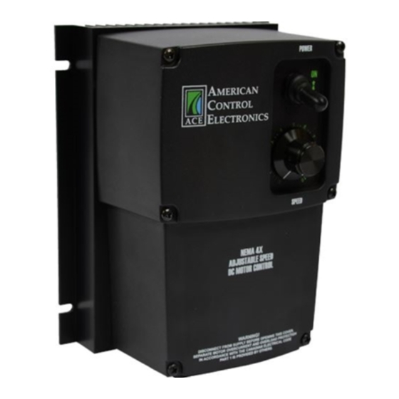
Mounting
NEMA 4X cased drives come with two 0.73 inch (18.5 mm) conduit holes at the bottom of the case.
The drives may be vertically wall mounted using the four 0.19 inch (5 mm) slotted holes on the
attached heat sink. For loads less than 5 amps, the drive may be bench mounted horizontally or
operated without mounting.
1. Install the mounting screws.
2. For access to the terminal strip, remove the six phillips screws on the front cover.
3. Remove the five phillips screws on the bottom plate. Do not remove the three screws securing the
3. bottom plate to the heat sink.
4. Set the POWER switch to the OFF position before applying AC line voltage.
5. Install conduit hardware through the 0.73 inch (18.5 mm) knockout holes. Connect external wiring
5. to the terminal block.
6. Place the front cover back into place. Avoid pinching any wires between the front cover and the
6. heat sink.
7. Reinstall the 6 screws on the front cover. The two shorter screws are for the two lower holes of the
7. front cover. Reinstall the 5 screws on the bottom plate.
Wiring
Use 14 - 16 AWG wire for AC line and motor wiring.
Shielding Guidelines
As a general rule, it is recommended to shield all conductors. If it is not practical to shield power
conductors, it is recommended to shield all logic-level leads. If shielding of logic-level leads is not
practical, the user should twist all logic leads with themselves to minimize induced noise. It may be
necessary to earth ground the shielded cable. If noise is produced by devices other than the drive,
ground the shield at the drive end. If noise is generated by the drive, ground the shield at the end
away from the drive. Do not ground both ends of the shield.
Fusing
The drive provides on board fusing for the AC line (L1, L2(230)). Fuses are fast acting fuses rated for
15A at 250 VAC.
PAT443
1Q SCR NEMA 4X Adjustable Speed Drive
for PMDC or Field Wound Brushed Motors
READ ALL SAFETY WARNINGS BEFORE INSTALLING THIS EQUIPMENT
Continuous
Armature
• DO NOT INSTALL, REMOVE, OR REWIRE THIS EQUIPMENT WITH POWER APPLIED. Have a
Armature
Horsepower
• qualified electrical technician install, adjust and service this equipment. Follow the National
Current (Amps)
Range
• Electrical Code and all other applicable electrical and safety codes, including the provisions of the
1/8 - 1
10.0
• Occupational Safety and Health Act (OSHA), when installing equipment.
1/4 - 2
• Circuit potentials are at 115 or 230 VAC above earth ground. Avoid direct contact with the printed
• circuit board or with circuit elements to prevent the risk of serious injury or fatality. Use a non-
• metallic screwdriver for adjusting the calibration trim pots. Use approved personal protection
• equipment and insulated tools if working on this drive with power applied.
• Reduce the chance of an electrical fire, shock, or explosion by proper grounding, over-current
• protection, thermal protection, and enclosure. Follow sound maintenance procedures.
• ACE strongly recommends the installation of a master power switch in the line voltage input. The
• switch contacts should be rated for 250 VAC and 200% of motor nameplate current.
• Removing AC line power is the only acceptable method for emergency stopping. Do not use
• dynamic braking, decelerating to minimum speed, or coasting to a stop for emergency stopping.
• They may not stop a drive that is malfunctioning. Removing AC line power is the only acceptable
• method for emergency stopping.
• Line starting and stopping (applying and removing AC line voltage) is recommended for infrequency
• starting and stopping of a drive only. Dynamic braking, decelerating to minimum speed, or coasting
• to a stop is recommended for frequent starts and stops. Frequent starting and stopping can produce
• high torque. This may cause damage to motors.
• Do not disconnect any of the motor leads from the drive unless power is removed or the drive is
• disabled. Opening any one lead while the drive is running may destroy the drive.
• The field output is for shunt wound motors only. Do no make any connections to F1 and F2 when
• using a permanent magnet motor.
• Change voltage switch settings only when the drive is disconnected from AC line voltage. Make sure
• both switches are set to their correct position. If the switches are improperly set to a lower voltage
Maximum Rating of
Overcurrent Protection
• position, the motor will not run at full voltage and may cause damage to the transformer. If the
• switches are improperly set to a higher voltage, the motor will overspeed, which may cause motor
• damage, or result in bodily injury or loss of life.
Inverse Time
30 A
• Under no circumstances should power and logic level wires be bundled together.
Circuit Breaker
Line Input
Connect the AC line power leads to terminals L1 and L2-115 if using 115 VAC line power or to terminals
L1 and L2-230 if using 230 VAC line power.
Motor
Connect the DC armature leads to terminals A1 and A2. If the motor does not spin in the desired direction,
Power down the drive and reverse these connections.
Field
At 115 VAC, connect the field leads to terminals F1 and L1 for a 50 VDC field or to F1 and F2 for a 100 VDC field.
At 230 VAC, connect the field leads to terminals F1 and L1 for a 100 VDC field or to F1 and F2 for a 200 VDC field.
Do not make any connections to F1 and F2 if using a permanent magnet motor.
Speed Potentiometer (Pre-wired)
PAT443 series drives are pre-installed with a 10K ohm, 1/4 W potentiometer for speed control. Set the switch
on the front cover to MANUAL to follow the potentiometer.
Analog Signal
Instead of using a speed adjust potentiometer, PAT443 series drives may be wired to follow an analog
input signal. This input signal can be in the form of voltage (0-10 VDC) or current (1-5, 4-20, or 10-50 mA).
Because these drives have built in isolation, the input signal can be grounded or ungrounded (floating).
Connect the signal common (-) to terminal 3 and the signal reference (+) to terminal 2 on the top board.
If using a 4-20 mA signal, place a 1000 ohm resistor (RSH) across terminals 1 and 4 on the top board.
If using a 10-50 mA signal, place a 250 ohm resistor (RSH) across terminals 1 and 4 on the top board.
Set the switch on the front cover to AUTO to follow the remote analog signal.
Inhibit
Short the INHIBIT terminals to coast the motor to minimum speed. Open the INHIBIT terminals to
accelerate the motor to set speed. Twist inhibit wires and seperate them from power-carrying wires or
sources of electrical noise. Use shielded cable if the inhibit wires are longer than 18 inches (46 cm). If
shielded cable is used, ground only one end of the shield to earth ground. Do not ground both ends of
the shield. Do not use the inhibit for emergency stopping.
ACE offers two accessory plug harnesses for connecting to the inhibit terminals; part number KTW-0001
[18 in (46 cm) leads] and part number KTW-0002 [36 in (91 cm) leads].
with Isolation
Safety Warnings
Connections
14300 De La Tour Drive
South Beloit, IL 61080
Phone: (844) AMCNTRL
Fax: (800) 394-6334
www.americancontrolelectronics.com
Full manual available online
Dimensions
5.63 [143]
5.16 [ 131]
MANUAL
SIGNAL
7.50 [191]
5.50 [140]
0.73 [18.5]
CONDUIT HOLES
2 PLACES
4.56 [116]
2.12 [53.8]
2.20
[55.9]
3.40
[86.4]
ALL DIMENSIONS IN INCHES [MILLIMETERS]
IC501
C502
IC1
R9
3
R7
2
R8
C4
SIG MIN.
SIG MAX
1
C501
IC502
SO501
P502
P501
PL501
PL502
DECEL
ACCEL
TQ LIMIT
D501
C3
D502
IR COMP
MIN. SPD
MAX SPD
T501
SW501
1
R5
R501
R6
2
3
4
230-115
TB501
Q2
R1
T501
C1
R3
RSH = 1000 OHM* for 4 - 20 mA
Q1
C2
R4
RSH = 250 OHM* for 10 - 50 mA
MOV501
RSH = NOT USED for 1 - 5 mA
RSH = NOT USED for 0 - 10V signal
R2
* Use 1/4 Watt 5% Tolerance
F502
L2 FRM SW L1
A2 TO SW A1
L2 TO SW L1
A2 FRM SW A1
F501
MOV503
TB501
+
NOTE: DO NOT make
230 VAC
any connections to
115 VAC
EARTH
LINE
F1 and F2 if using a
GROUND
MOTOR
VOLTAGE
permanent magnet motor .
(GREEN
FIELD
ARMATURE
INPUT
SCREW)
OUTPUT
(115 or 230 VAC)
0.19 [5.00]
SLOTTED HOLES
4 PLACES
BOTTOM PLATE
Inhibit
Terminals
1
2
3
4
TB501
RSH
TERMINAL 2
TERMINAL 3
(+) Reference
(-) Common
Advertisement
Table of Contents

Related Manuals for American Control Electronics PAT443


Summary of Contents for American Control Electronics PAT443
- Page 1 TB501 PAT443 series drives are pre-installed with a 10K ohm, 1/4 W potentiometer for speed control. Set the switch 7. Reinstall the 6 screws on the front cover. The two shorter screws are for the two lower holes of the on the front cover to MANUAL to follow the potentiometer.
- Page 2 INHIBIT CW for a longer deceleration time, or CCW for a shorter deceleration time. Repeat steps 1 ® merchantability and fitness for a given purpose. American Control Electronics assumes no through 3 until the deceleration time is correct. responsibility for any errors that may appear in this document and makes no commitment to update or to keep current the information in this document.
Need help?
Do you have a question about the PAT443 and is the answer not in the manual?
Questions and answers