Table of Contents
Advertisement
Quick Links
Instruction Manual
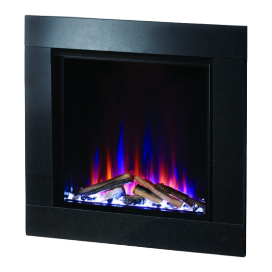
eTronic 560 Slimline
This product is only suitable for well insulated spaces or occasional use.
To be left with the customer after demonstrating the features of the Solution electric fire.
The complete installation must be carried out in accordance with current Standards and Local
Codes. The instructions in this manual must be followed to ensure safe operation of the appliance.
It should be noted that the requirements and this publication may be superseded during the life of
the Fireplace - please refer to www.solutionfires.co.uk for up-to-date instructions.
The product complies with the European Safety Standards EN60335-2-30 and the European
Standard Electromagnetic Compatibility (EMC) EN55014, EN60555-2 and EN60555-3. These cover
the essential requirements of EEC Directives 2006/95/EC and 2004/108/EC
June 2022 V1
Advertisement
Table of Contents

Related Manuals for Solution FIres eTronic 560 Slimline


Summary of Contents for Solution FIres eTronic 560 Slimline
- Page 1 Instruction Manual eTronic 560 Slimline This product is only suitable for well insulated spaces or occasional use. To be left with the customer after demonstrating the features of the Solution electric fire. The complete installation must be carried out in accordance with current Standards and Local Codes.
-
Page 2: Table Of Contents
Setting the Time and Day (24 Hour Clock)......................Setting the Weekly Timer............................ Thermal Safety Cut-Out............................Light Emitting Diode............................Cleaning, Servicing and Maintenance......................Correct Disposal of this Product........................Battery Replacement Remote Control......................Troubleshooting..............................Solution Fires Warranty............................Exploded View..............................Replaceable Parts............................. Wiring Diagram.............................. -
Page 3: Important Safety Advice
Important Safety Advice When using electrical appliances, basic precautions should be followed to reduce the risk of fire, electric shock, and injury to persons, including the following: • WARNING: If the appliance is damaged, check immediately with your retailer before installation and operation. - Page 4 • Use only a dry duster or vacuum cleaner with brush attachment to clean the appliance. Never use abrasive cleaners, water, steam cleaners or aerosols on or near the appliance. • Only control the appliance using the manual operations or the supplied remote control described in this manual.
-
Page 5: Technical Parameters
Technical Parameters Information requirements for electric local space heaters Model identifier(s): eTronic 560 Slimline Item Symbol Value Unit Item Unit Heat output Type of heat input, for electric storage local space heaters only (select one) Nominal heat output manual heat charge control, with... - Page 6 Technical Parameters Dimension (mm) Note: Dimensions stated are in millimetres unless otherwise stated and may be subject to a slight +/- variation. Technical Data Voltage 220-240V AC ~50-60 Hz Max Power 1700-2000W Gross Weight (kgs) 25.8kg Efficiency Rating Commissioning and Handover On completion of the installation: •...
-
Page 7: Installation & Operating Instructions
Installation and Operating Instructions Box Contents: NOTE: Hardware not shown to actual size. Ref. Description Quantity Fireplace Top Wall bracket (A) Various Long Screw (CC) Various Wall Anchors (EE) Various Remote control AAA Batteries 1set (2pcs) Planning Assembly Before beginning assembly of product, make sure all parts are present. Compare parts with package contents lists. - Page 8 Installation and Operating Instructions Installation IMPORTANT: Do not connect the appliance until it is properly fixed to the wall and the instruction have been read fully. Ensure the minimum distances are observed. 1. Choosing a Wall Location • Choose a wall location to attach the Top Wall Bracket (A). Position the Top Wall Bracket (A) in the desired location.
- Page 9 Installation and Operating Instructions 4. Hanging the Fireplace • Ensure the Top Wall Bracket (A) is secured into the Wall Anchors. • Lift the Fireplace (a second person may be required), and align the slots on back panel with the hooks on Wall Bracket (A).
- Page 10 Installation and Operating Instructions The unit can be operated either by the key board (located just above the flame screen, on the right side), or using the remote control supplied. For the unit to operate, the manual ON/OFF switch, located on the left side of the grille panel must be switched to the “I”...
-
Page 11: Powering The Fireplace
Operating Instructions Continued NOTE: The unit may emit a slight, harmless odour and smoke when first used. This odour & smoke is normal and it is caused by the heating of the internal heater parts and will not occur again. NOTE: The function below can be controlled either by key board or remote control. -
Page 12: Flame Operation
Operating Instructions Continued Flame Operation Fuel Bed Colours 1. Orange fuel bed (default) By pressing the Flame Preset button (Flam), you 2. Red fuel bed can select from 8 different flame effect options: 3. Purple fuel bed 1. 100% Amber flame picture (default) 4. -
Page 13: Setting The Weekly Timer
Operating Instructions Continued Setting the Weekly Timer The Timer allows for two ON/OFF periods (M1/M2) for each day of the week and the timer can be set using the following procedure: 1. Press the Power button to turn the unit on. 2. -
Page 14: Thermal Safety Cut-Out
Thermal Safety Cut-Out A thermal safety cut-out is incorporated in the heater to prevent damage due to overheating. This can happen if the heat outlet is restricted in any way. The heater will switch on once the obstruction has been removed and the heater has cooled. -
Page 15: Battery Replacement Remote Control
Battery Replacement Remote Control Battery information - see Fig. 19 1. Slide open the battery cover on the back of the remote control. 2. Install AAA batteries into the remote control. 3. Replace the battery cover. Fig. 19 Discard leaky batteries Dispose of batteries in the proper manner according to local regulations. -
Page 16: Troubleshooting
Troubleshooting (IF IN DOUBT isolate the appliance and seek professional advice) The unit does not switch on: • Check main power on/off switch is on and orange light on flame screen illuminates. • Check the battery in the remote control handset. •... -
Page 17: Solution Fires Warranty
Solution Fires Warranty All Solution Fires come with a standard 1 year parts Should you experience problems with your Solution warranty extendable to 2 years on registration. Fire, any claim must be submitted to the Solution Any fire purchased outside of our authorised... -
Page 18: Exploded View
Exploded View Replaceable Parts Description Part Number Front Glass 22 03 196 Flame Screen 22 03 199 Flame LEDs 22 03 201 Fuel Bed LED Strip 22 03 203 Motor 22 03 204 Display/IR Receiver 22 03 194 Remote Handset 22 03 120 On-Board Control PCB Board 22 03 206... -
Page 19: Wiring Diagram
Wiring Diagram... - Page 20 www.solutionfires.co.uk info@solutionfires.co.uk CAPITAL FIREPLACES LTD, Unit 12-17 Henlow Trading Estate, Henlow Camp, Bedfordshire, SG16 6DS. UK.
Need help?
Do you have a question about the eTronic 560 Slimline and is the answer not in the manual?
Questions and answers