Table of Contents
Advertisement
Quick Links
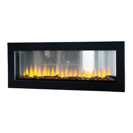
Instruction Manual - SLE125t
Instruction Manual - SLE125t
with etronic 3D flame technology
This product is only suitable for well insulated spaces or occasional use.
This product is only suitable for well insulated spaces or occasional use.
To be left with the customer after demonstrating the features of the Solution SLE125t electric fire.
To be left with the customer after demonstrating the features of the Solution SLE125t electric fire.
The complete installation must be carried out in accordance with current Standards and Local Codes. The instructions
The complete installation must be carried out in accordance with current Standards and Local Codes. The instructions
in this manual must be followed to ensure safe operation of the appliance. It should be noted that the requirements
in this manual must be followed to ensure safe operation of the appliance. It should be noted that the requirements
The product complies with the European Safety Standards EN60335-2-30 and the European Standard Electromagnetic Compatibility (EMC)
The product complies with the European Safety Standards EN60335-2-30 and the European Standard Electromagnetic Compatibility (EMC)
EN55014, EN60555-2 and EN60555-3. These cover the essential requirements of EEC Directives 2006/95/EC and 2004/108/EC
EN55014, EN60555-2 and EN60555-3. These cover the essential requirements of EEC Directives 2006/95/EC and 2004/108/EC
July 2020 - V1
July 2020 - V1
and this publication may be superseded during the life of the fireplace.
and this publication may be superseded during the life of the fireplace.
Advertisement
Table of Contents

Related Manuals for Solution FIres SLE125t


Summary of Contents for Solution FIres SLE125t
- Page 1 This product is only suitable for well insulated spaces or occasional use. To be left with the customer after demonstrating the features of the Solution SLE125t electric fire. To be left with the customer after demonstrating the features of the Solution SLE125t electric fire.
-
Page 2: Table Of Contents
Flame Brightness Operation........................Setting the Time and Day (24 Hour Clock)....................Setting the Weekly Timer..........................Thermal Safety Cut-Out..........................Light Emitting Diode............................. Battery Replacement Remote Control...................... Troubleshooting............................Cleaning, Servicing and Maintenance..................... Replaceable Parts............................Wiring Diagram............................. Correct Disposal of this Product........................Solution Fires Warranty.......................... -
Page 3: Important Safety Advice
Important Safety Advice When using electrical appliances, basic precautions should be followed to reduce the risk of fire, electric shock, and injury to persons, including the following: WARNING: Read these instructions completely before beginning installation. Failure to follow them could cause an appliance malfunction. WARNING: If the appliance is damaged, check immediately with your retailer before installation ... - Page 4 Unpack the fire from the box and remove the packing pieces from each end by taking out the four screws each end. Using the eight 8mm number 2 screws supplied please fill the carriage holes left by removing the carriage packing. Before proceeding to install the SLE125t please plug it in and test it works correctly.
-
Page 5: Handover
Dimensions Note: Dimensions stated are in millimetres unless otherwise stated and may be subject to a small tolerance. Commissioning and Handover On completion of the installation: • Ensure that the operating instructions for the unit are left with the customer. •... -
Page 6: Installation And Operating Instructions
Installation Recessing the Appliance into the Wall Due to the many different finish materials used on walls, it is highly recommended that you consult your local retailer/fitter before you install this appliance in the wall. Select a location that is not prone to moisture and is located at least 36”... - Page 7 C. Remove the front trims, see below. Front Trim Removal WARNING: BEFORE THE FRONT TRIM IS REMOVED OR INSTALLED UNPLUG THE APPLIANCE AND WAIT UNTIL THE APPLIANCE IS COOL TO THE TOUCH. THE TRIM CAN BE HEAVY AND FRAGILE SO HANDLE WITH CARE.
- Page 8 D. Remove the front glass, see below. Front Glass Removal WARNING: BEFORE THE FRONT GLASS IS INSTALLED OR REMOVED UNPLUG THE APPLIANCE AND WAIT UNTIL THE APPLIANCE IS COOL TO THE TOUCH. GLASS CAN BE HEAVY AND FRAGILE SO HANDLE WITH CARE.
- Page 9 E. Install mounting bracket by aligning the edge 6.4mm from the centre of the wall sides and 156mm from the bottom of the wall sides. Fig. 6 Use a pencil to mark through the holes on the wall brackets. Fig. 7 F.
- Page 10 I. Install the log set to suit your own style. Install the front trim by aligning with the pins on the appliance. This ensures the touch display panel performs properly. Installation - Suggested Log Layout NOTE: There is no particular requirement to lay out the logs as shown in the photographs above. The only requirement is that the small triangular openings in the fuel bed of Side B of the fire - any encroachment on this area will reduce the effectiveness of the flame effect.
- Page 11 Front Trim Installation A. Lift the trim and ensure the trim top lines up with the appliance top, then push in until the trim drops down and sits on the appliance by aligning the slots in the trim with the pins on the appliance.
-
Page 12: Operational Instructions
Operating Instructions WARNING: WHILE THE APPLIANCE IS OPERATING DO NOT REMOVE THE GLASS PANEL. THIS WILL CAUSE THE REMOTE CONTROL AND MANUAL CONTROL PANEL TO MALFUNCTION. ! NOTE: The unit can be operated on the manual control panel and with the supplied remote control. -
Page 13: Powering The Fire
Operation Continued NOTE: The unit may emit a slight, harmless odour and smoke when first used. This odour & smoke is normal and it is caused by heating the internal heater parts and will not occur again. NOTE: Ensure the manual ON/OFF switch located under the top bar of the trim (see fig. 15) is switched to the “I”... -
Page 14: Flame Operation
IMPORTANT NOTE: The fan will run for Open Window Device function: approximately 10 seconds after the Heating To ensure minimum energy wastage, this function is turned off to remove any residual appliance will turn off the heaters should an heat from the unit to protect the control open door or window be detected. -
Page 15: Setting The Time And Day (24 Hour Clock)
Operation Continued Fig.23 Fig.24 Setting the Time & Day (24 Hour Clock) 1. Press the Power button to turn the unit on. 2. Press & hold the Time Setting button for two seconds to display the time & day see Fig 23 (no numbers shown as time not set). -
Page 16: Thermal Safety Cut-Out
Cleaning Battery Replacement NOTE: Allow the fire to completely cool Remote Control before cleaning it. 1. Switch off and unplug from the power Battery information - see Fig. 31 supply before cleaning. 1. Slide open the battery cover on 2. Using a soft, dry cloth, carefully clean the back of the remote control the exterior surface of the product. - Page 17 Technical Parameters Information requirements for electric local space heaters Model identifier(s): SLE125t Item Symbol Value Unit Item Unit Type of heat input, for electric storage local space Heat output heaters only (select one) manual heat charge control, with [no] Nominal heat output...
-
Page 18: Troubleshooting
Troubleshooting WARNING: TURN OFF THE APPLIANCE COMPLETELY AND LET COOL BEFORE SERVICING. ONLY A QUALIFIED SERVICE PERSON SHOULD SERVICE AND REPAIR THIS ELECTRIC APPLIANCE. My fire makes some sounds Your fire will make some sounds during normal operation. There are three sources of sound: 1. - Page 19 Exploded View...
-
Page 20: Cleaning, Servicing And Maintenance
Replaceable Parts DESCRIPTION PART NO REMOTE CONTROL HANDSET 22 03 060 FRONT GLASS (BOTH SIDES) 22 03 095 FLAME SCREEN 22 03 096 FUEL BED FRONT 22 03 097 FUEL BED REAR 22 03 098 FLAME EFFECT LIGHTS 22 03 099 FUEL BED LIGHTS-6RGBS 22 03 100 FUEL BED LIGHTS-9RGBS... -
Page 21: Wiring Diagram
Wiring Diagram WARNING: TURN OFF THE APPLIANCE COMPLETELY AND LET COOL BEFORE SERVICING. ONLY A QUALIFIED SERVICE PERSON SHOULD SERVICE AND REPAIR THIS ELECTRIC APPLIANCE. -
Page 22: Correct Disposal Of This Product
LED boards, ceramic logs, fuses and is prohibited by statute. Solution Fires, in the event of a batteries which are either subject to normal wear and warranty claim, reserves the right to either replace the... - Page 23 Notes...
- Page 24 www.solutionfires.co.uk info@solutionfires.co.uk Capital Fireplaces, Units 12-17 Henlow Trading Est, Henlow, Bedfordshire SG16 6DS...
Need help?
Do you have a question about the SLE125t and is the answer not in the manual?
Questions and answers